
Abstract
This article addresses one quadruple-rudder allocation method for an autonomous underwater vehicle (AUV) equipped with X rudder, in which all of the rudders can be operated independently. By considering X rudder’s character, one X-rudder AUV’s control information frame is designed. It contains the anti-normalization method based on virtual rudders and one quadruple-rudder allocation with Lévy flight character. This quadruple-rudder allocation method has the advantages of Lévy flight and avoids the shaking problem. One contrast simulation of a lawn mower path following mission in three-dimensional (3D) space is performed. The results of simulation show that the quadruple-rudder allocation with Lévy flight character can offer accurate and reliable control ability. Besides that, compared to the quadruple-rudder allocation based on pseudoinverse and fixed point iteration, the method designed with Lévy flight character can achieve the same mission with less X rudder’s operation.
Keywords
Introduction
Autonomous underwater vehicles (AUVs) can work under water without requiring inputs from operators. AUVs are playing more and more important roles in exploring and developing the ocean, such as bottom topographic survey and the exploring of submarine hydrothermal sulfide. 1,2 AUVs can also extend men’s ability and do the work that is much more difficult for humans, such as detecting mines in harbour, checking oil pipes’ safety and finding crashed planes’ wreckage in deep sea. 3 –5 The multiple kinds of work for AUVs come from the researchers’ study. They never stop trying to push forward the limit of AUV’s control ability.
Some researchers try to design new control methods. Kumar et al. proved the modified gain extended Kalman filter in AUV’s obstacle avoidance and navigation. 6 Elmokadem et al. proposed one trajectory tracking control using the sliding mode control technique for underactuated AUV. 7 Wan et al. designed one bottom following method based on active disturbance rejection control for AUV in complex environment. 8 Wang et al. adjusted the force allocation strategy and motion control method to make one AUV finish tasks while the dynamic positioning function is reserved. 9 Podder et al. designed an allocation of thruster forces for one AUV to produce desired force when AUV is in trouble. 10 Besides, some of the researchers try to design new motion operators. Pyo et al. specially designed a hovering-type AUV with symmetric body structure and thruster for a lawn mower trajectory. 11 Ma et al. developed a cownose ray-inspired robotic fish that can be propelled by oscillation and chordwise twisting pectoral fins. 12 As mentioned before, X rudder is one of the new motion operators.
Traditional cross rudder is usually composed of two parts, one is horizontal rudder and the
other is vertical rudder. They are usually placed at the stern of one vehicle. As to X
rudder, it usually forms the shape of X at the bow or stern of one vehicle. According to the
available literature, X rudder can be classified into three kinds as follows: Fixed X rudder: The rudders of this kind of X rudder cannot be operated. Liu et al.
designed one AUV equipped with this kind of X rudder at stern.
13
The AUV’s motion control is fulfilled by the vertical and horizontal tunnel
propellers and four main thrusters. This X rudder is fixed and its function is just to
offer the extra stability when AUV moves. Diagonal-linkage X rudder: This kind of X rudder is driven in the unit of a diagonal
rudder pair. Yoshida et al. designed one AUV called Yumeiruk equipped with two X rudders.
14
One is at the bow and the other one is at the stern. The AUV can use them to
cause the corresponding moments to control yaw and pitch. In March 2013, the 15-days
sea trial of the AUV was carried out in the Sagami Bay. The diagonal-linkage X rudder
is used during altitude changes. Independent X rudder: This kind of X rudder can be operated independently. According
to the available literature, it has not been used by AUV. However, it has been studied
by some countries’ navy and been equipped on some submarines, such as Gotland class
from Sweden, Type 212A from Germany and Soryu class from Japan.
The available literature about X rudder control is very rare and similar. They just mention some advantages of X rudder on submarines compared to traditional cross rudder or the relationship between X rudder and traditional cross rudder. 15 However, it does not mention any details about auto control of X rudder, especially the quadruple-rudder allocation method. So our research pays more attention to the independent X rudder and the situation of four rudders being responsible for AUV’s motion control.
In this article, the whole auto control information framework of X-rudder AUV and one quadruple-rudder allocation with Lévy flight character are designed. By considering X rudder’s character and practical situation, the information framework includes the anti-normalization part based on virtual rudders and rudder allocation part. The anti-normalization method based on virtual rudders is used to solve the abstract situation of X rudder’s control. The quadruple-rudder allocation with Lévy flight character belongs to the rudder allocation part. The simulation test shows that the quadruple-rudder allocation with Lévy flight character has efficient and accurate responses to corresponding commands.
The remainder of this article is organized as follows. In ‘Model description of an X-rudder AUV’ section, X-rudder AUV’s kinematics equations, dynamics equations and corresponding parameters are offered. In ‘Quadruple-rudder allocation based on pseudoinverse and fixed point iteration’ section, the control information frame of X-rudder AUV is designed. It mainly contains anti-normalization and quadruple-rudder allocation based on pseudoinverse and fixed point iteration. In ‘Lévy flight quadruple-rudder allocation and its optimization’ section, one quadruple-rudder allocation with Lévy flight character is designed. It contains the thought of Lévy flight and multi-objective optimization. In ‘Simulation and results’ section, the results and analysis of comparative simulation in a 3D lawn mower path following mission are presented.
Model description of an X-rudder AUV
Coordinate systems and kinematic and dynamic models
The test X-rudder AUV’s appearance and corresponding coordinate systems are shown in
Figure 1. Two coordinates are
designed. One is a body-fixed frame

X-rudder AUV and coordinate systems. AUV: autonomous underwater vehicle.
The kinematics and dynamics equations of an AUV in 3D space can be described as follows 16


where


X rudder’s layout and its main parameters
X rudder’s layout and the rudder numbers are shown in Figure 2. Serial numbers are used to simplify the description of X rudder’s control. The rudder’s angle is positive, while the rudder can cause the corresponding force direction shown in Figure 2.

Layout of X rudder.
Equation (3)
shows the relationship between

where
As to the test X-rudder AUV in this article, its mass is 1420 kg and its length is 6 m. Its moments of inertia of the coordinate axes x, y and z in {B} are 17, 1835 and 1800 kg m2, respectively. Some other main parameters about X rudder are shown in Table 1. They are calculated by computation fluid dynamics methods and they will be used in the simulation tests.
Main parameters of the X rudder.

Quadruple-rudder allocation based on pseudoinverse and fixed point iteration
The X rudder control information frame
If the control law is based on error and the rate of error, cross-rudder AUV’s and X-rudder AUV’s control information frames can be described as shown in Figure 3. In Figure 3, the function of {B} to {N} is used to transform the values in coordinate system {B} to coordinate system {N}. It is obvious that the rudder allocation is one unique part in X-rudder AUV’s control, which cross-rudder AUV does not have. However, the anti-normalization in X rudder control should be analysed first not only because this part is different from traditional cross rudder control but also this is the foundation of rudder allocation part in X rudder control.

Cross-rudder AUV’s and X-rudder AUV control information frames. AUV: autonomous underwater vehicle.
Anti-normalization
In traditional cross-rudder AUV’s control, the anti-normalization part can be explained by the following

where CTRyaw_cross and CTRpitch_cross are the outputs of vertical rudder’s and horizontal rudder’s control laws, respectively, δv_max and δh_max are the maximum values of the corresponding cross rudder and δv and δh are the vertical and horizontal rudders, respectively. They can affect yaw and pitch separately.
However, according to equation (3), any X rudder’s operation can
cause changes to all the values in matrix

where
However, virtual rudders are not the direct causes of the changes of
[K, M, N] in
Rudder allocation
As to one independent X-rudder AUV, one of its great unique characters is its rudders’ operation. These rudders’ operation is very flexible because there are many combination kinds. For example, the X-rudder AUV’s motion control can be achieved by double-rudder, triple-rudder or quadruple-rudder allocation. According to our research, double-rudder allocation and triple-rudder allocation can be designed as equations (6) and (7) referring to under-actuated AUV’s control and full-actuated AUV’s control 17


where K*, M* and
N* are shown in equation (3).
δVR_roll, δVR_pitch and
δVR_yaw are shown in equation (5).
δ* represents rudder *, which is responsible for X-rudder
AUV’s control.
Compared with double-rudder allocation and triple-rudder allocation, quadruple-rudder allocation is more complex and confusing. To the X-rudder AUV’s control, quadruple-rudder allocation should be paid more attention here and its control method should be efficient and accurate.
Quadruple-rudder allocation
Problem description and pseudoinverse method
The quadruple-rudder allocation can be described as follows

Equation (8) can be simplified as follows
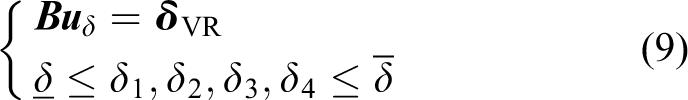
where

Before solving equation (9), Rank( If If If
When solving the problem as equation (9), the method of pseudoinverse 19 shown in equation (10) can be used

where
If
X-rudder resistance and fixed point iteration
Any movement of X rudder can change φ, θ and ψ directly, besides that, the movement of X rudder can also cause resistance against AUV’s forward movement. The resistance of one rudder’s operation can be described by the following

where Fre is the resistance force caused by one rudder’s operation. ρ, CD, vf, Srudder and δ represent density of environment, drag coefficient, 20 flow velocity to rudder, area of the rudder and rudder angle, respectively. Re is the energy cost by resistance, T is the time length of AUV’s mission and u is AUV’s velocity. The sum of X rudder’s Re can be called as ReTotal, which can be calculated by the following

where i represents the rudder’s number in X rudder and ReTotal is the whole energy consumption generated by the X rudder’s movements.
In this article, the X rudder’s appearances are the same and X rudder’s design is based on NACA0012. 21 The whole CD curve and a part of CD curve from 0° to 35° are shown in Figures 4 and 5, respectively. Curve in Figure 5 can be described as follows


CD of NACA0012.
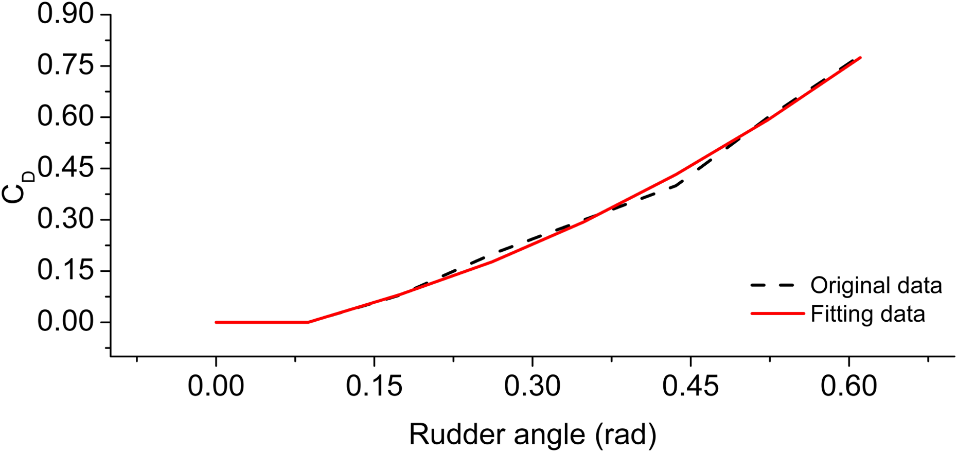
A part of CD and fitting curve.
where δ is rudder’s angle in the unit of rad. 1 rad = 180/π deg.
According to equations (11)–(13), the less operation of rudders, the
less energy the X-rudder AUV consumes. As to the solution of equation (10) in
situation
where

where
If

where

When

where Jend is an adjustable parameter. Equation (18)
shows the situation of the kth iteration and
The whole process of quadruple-rudder allocation based on pseudoinverse and fixed point iteration is shown in Figure 6.

The information framework of quadruple-rudder allocation based on pseudoinverse and fixed point iteration.
Lévy flight quadruple-rudder allocation and its optimization
Lévy flight quadruple-rudder allocation
According to the analysis in ‘Quadruple-rudder allocation’ section, when
Lévy flight is named by French mathematician Paul Lévy. It is a random walk in which the
step-lengths have a probability distribution that is heavy-tailed. When defined as a walk
in a space of dimension greater than one, the steps made are in isotropic random directions.
24
In X rudder control, Lévy flight is used to complete the global search part and
fixed point iteration in ‘Quadruple-rudder allocation’ section is used to complete the
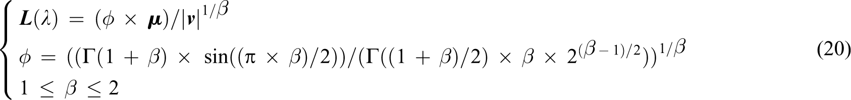
local search part during solving the problem as equation (15). Lévy flight in X rudder
control can be described as equation (19). The pseudoinverse results in
‘Quadruple-rudder allocation’ section can be used as one initial point, and the end of
Lévy flight can be decided by the flight’s times

where
where

Every time Lévy flight is done, there will be several new points and the points number is
the same as NL. Plus the initial point in Lévy flight, there
can be NL + 1 points, and they can be the original iteration
points in fixed point iteration mentioned in ‘Quadruple-rudder allocation’ section. Once
all the fixed point iterations are done, all the

where
Here, one simulation of Lévy flight quadruple-rudder allocation is made without the fixed
point iteration part. One assumption is made as

The space of
Four initial points are designed. They are (0,0,0,0) calculated by pseudoinverse and three other points are calculated by equation (22). The flight’s time is five. Table 2 and Figure 8 show the detailed process of Lévy flight in 3D.

3D: three dimensional.

Lévy flight and partial enlarged detail.
In Figure 8, it can be found that the step length and the direction between the Lévy flight points are not the same. With the help of Lévy flight, the initial point can move in random direction. Usually it moves by small steps and occasionally by one big step. This character can prevent the repeated research in one small field and avoid the locally optimal solution compared to the quadruple-rudder allocation mentioned in ‘Quadruple-rudder allocation’ section.
According to the analysis in this section, the information frame of Lévy flight quadruple-rudder allocation can be built as Figure 9.

Control information frame of Lévy flight quadruple-rudder allocation.
In Figure 9,
Simulation of depth control is used to test the whole control method. X-rudder AUV’s origin depth is 10 m, expected depths are 40 and 80 m separately, origin yaw angle is 0°, and it will keep this yaw angle during the whole test. The classical PD control is chosen as the control law here. 26 AUV’s test speed is 3 m/s. There are one initial Lévy flight point calculated by pseudoinverse and three extra initial Lévy flight points calculated by equation (22). The flight’s times are five. The maximum angular velocity of X rudder is 1°/s. The angle range of X rudder varies from −35° to 35°. Figure 10 shows the control results.

Depth control results by Lévy flight quadruple-rudder allocation. (a) Depth curve. (b) Pitch angle curve. (c) X rudder curve of 80 m control.
The Lévy flight quadruple-rudder allocation designed in this section can achieve the depth control; however, Figure 10(c) shows that the X rudder shakes strongly, which should be avoided in AUV’s control. As to the situation of X rudder curve, the rudder curve of 40 m control is similar to the curve of 80 m control. That situation is obviously related to Lévy flight’s random step character.
Optimization for Lévy flight quadruple-rudder allocation
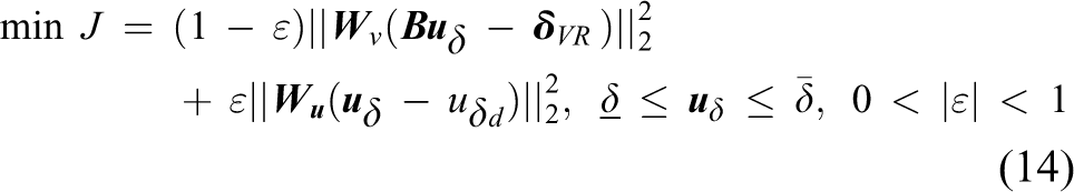
The thought of multi-objective optimization is used to balance the influence of Lévy flight’s random step character, which is used to avoid locally optimal solution and is also one main cause of the X rudder shaking situation. Even though multi-objective optimization cannot make every objective get the best answers, it can balance every objectives in the best way. Considering the X rudder shaking situation shown in Figure 10(c), one new objective is designed, and it is shown as follows

where

There are many methods to solve the multi-objective optimization, and one method called transformation 27 is chosen here. Its basic thought is to transform the multi-objective optimization to single-objective optimization according to the objective’s form. In order to achieve this goal, equation (23) is transformed into equation (25)

where

Equation (26) can be solved by the method mentioned in ‘Quadruple-rudder allocation’ section. This optimized allocation can be called as quadruple-rudder allocation with Lévy flight character.
The simulations of 40 m depth control and 80 m depth control are used to test this
quadruple-rudder allocation with Lévy flight character. X-rudder AUV’s origin situation,
initial Lévy flight point’s situation, corresponding parameters and motion executor’s
situation are the same as the depth control test in ‘Lévy flight quadruple-rudder
allocation’ section.

Depth control results by quadruple-rudder allocation with Lévy flight character. (a) Depth curve. (b) Pitch angle curve. (c) X rudder curve of 80 m control.
Compared with Figure 10(c) and 11(c), it can be found that the X rudder’s shaking situation is greatly restrained. Quadruple-rudder allocation with Lévy flight character is working.
Simulation and results
In order to show the control ability of quadruple-rudder allocation with Lévy flight character, which will be called QR with Lévy flight character in the following part, one comparison test with the quadruple-rudder allocation without Lévy flight character discussed in ‘X rudder resistance and fixed point iteration’ section is made, which will be called former QR in the following part. The whole process of following one lawn mower path in three dimension environment is simulated, and the process can be mainly separated into two steps. The first step is the control from X-rudder AUV’s start point (0,0,10) to expected depth (30 m) by certain yaw angle (30°). The second step is X-rudder AUV following the certain path after reaching the desired depth. The expected path is the connection of P1 (850,1700,30), P2 (3250,4100,30), P3 (4450,2900,30), P4 (2050,500,30), P5 (3250,−700,30), P6 (5650, 1700,30), P7 (6850,500,30) and P8 (4450,−1900,30). The control law is based on traditional PD control, and the path following strategy is designed by the line of sight guidance method. 28
The basic line of sight guidance method can be explained by Figure 12.

One situation of line of sight guidance method.
In Figure 12, AUV will try to follow the path from P1 to P2. ψline, ψdesign and ψexpect are the corresponding angles shown in Figure 12. ψline can be calculated by the coordinates of P1 and P2. ψdesign can be calculated by the following

where d is the distance between AUV and P1P2, and
lAUV is the length of AUV. So, in Figure 12, expected yaw angle
ψexpect can be calculated as
In simulation, the following assumptions and arrangements are made: X-rudder AUV is neutrally buoyant. All the preset points on the path are reachable. The disturbance is ignored in the environment, so that the flow velocity to rudder is
equal to X-rudder AUV’s velocity in equation (11). The same parameters’ values are the same in QR with Lévy flight character and former
QR. In the fixed point iteration part, In the Lévy flight part, α = 0.01 in equation (19), β = 1.5
in equation
(20) and
X-rudder AUV’s parameters have been mentioned in ‘X rudder’s layout and its main parameters’ section, and its original state is static. Its original yaw angle, pitch angle and X rudder’s angle are 0°. The maximum angular velocity of every rudder in X rudder is 1°/s. The range of X rudder is from −35° to +35°. X-rudder AUV’s expected speed is 3 m/s. The sample interval is 0.5 s. Runtime of the whole situation is 7000 s. The simulation results are shown in Figures 13 –17.

X-rudder AUV’s path following results. AUV: autonomous underwater vehicle.

Depth and yaw control results by quadruple-rudder allocation. (a) Depth controlled by former QR. (b) Yaw controlled by former QR. (c) Depth controlled by QR with Lévy flight character. (d) Yaw controlled by QR with Lévy flight character.
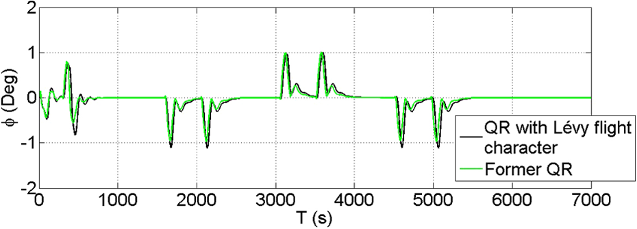
The situation of roll angle.

Number of iterations during former QR control.
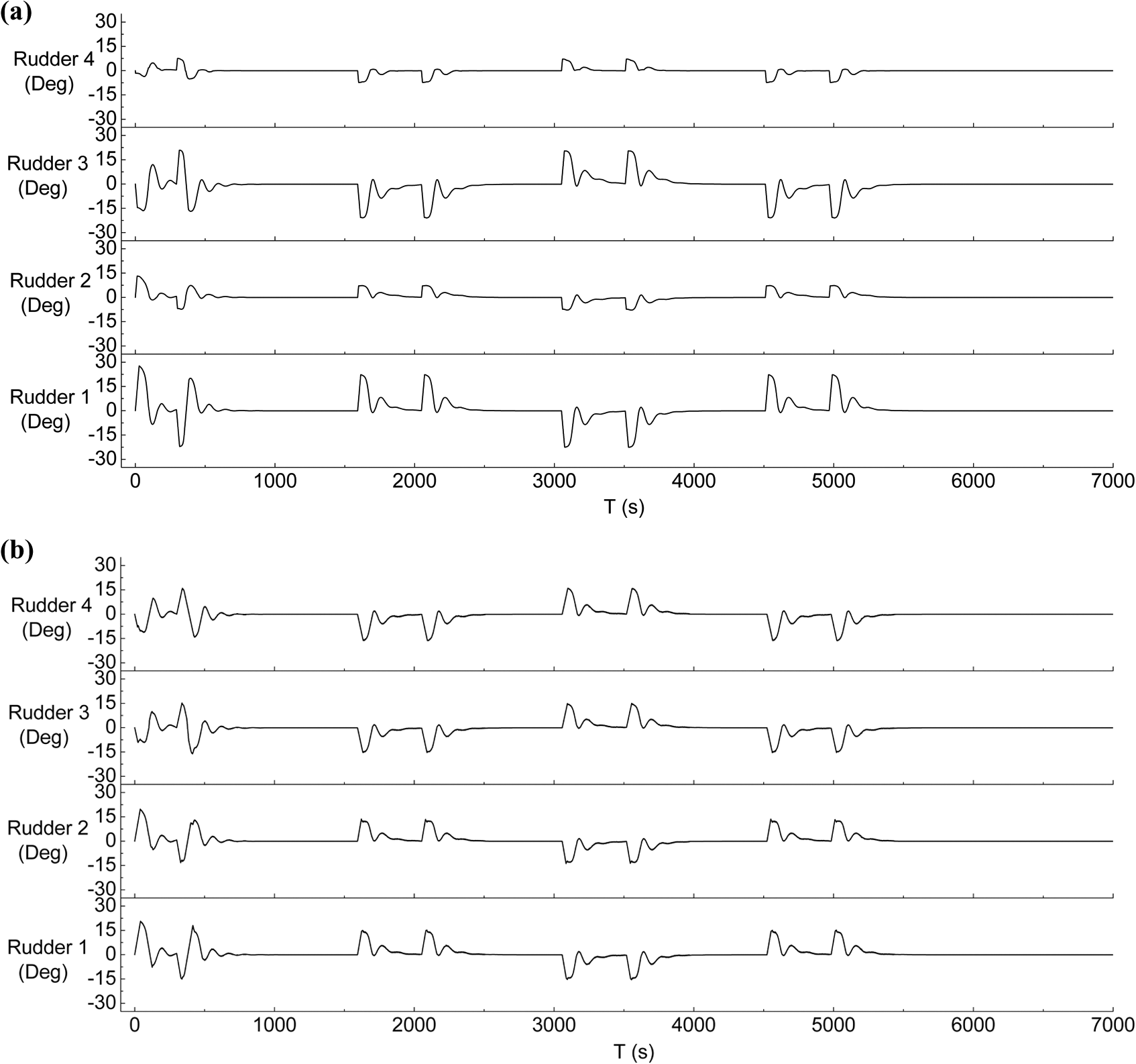
X-rudder angle curve of quadruple-rudder allocation. (a) X-rudder angle curve of former QR. (b) X-rudder angle curve of QR with Lévy flight character.
Figures 13–14 show that both former QR and QR with Lévy flight character can complete the mission. Their responds to the expected yaw angle are efficient and accurate. Figure 15 shows the changes of X-rudder AUV’s roll angle during the simulation. The maximum absolute value of roll angle controlled by former QR is 1.01° at t = 3580 s and the maximum absolute value of roll angle controlled by QR with Lévy flight character is 1.12° at t = 5066 s. That means X-rudder AUV controlled by both quadruple-rudder allocation methods mentioned in ‘X rudder resistance and fixed point iteration’ section and ‘Optimization for Lévy flight quadruple-rudder allocation’ section can achieve the lawn mower path following mission in a very stable way, and it will be essential for the work of acoustic and visual equipment on X-rudder AUV.
Figure 16 shows the number of iterations situation in former QR. The number of fixed point iteration does not increase forever, which means the fixed point iteration has run well. The situation of fixed point iteration in QR with Lévy flight character will be nearly the same as Figure 16.
Figure 17 shows the X-rudder’s changes during the simulation test. The X-rudder controlled by both methods does not appear the situation of strong shaking. According to Figure 17(a), the control load is mainly on Rudder 1 and Rudder 3 in former QR’s control. However, it seems X rudder’s operation of QR with Lévy flight character is more average than the operation of former QR.
Figure 18 shows the ReTotal’s curve calculated by equation (12) during the whole mission. During the calculation, the area of every rudder in X-rudder AUV is assumed as 1. The unit is not mentioned here, which will not affect the analysis conclusion. When the simulation ends, ReTotal of X rudder controlled by former QR is 1468 and ReTotal of X rudder controlled by QR with Lévy flight character is 964.4. This means that, during this mission, the X rudder’s operation by QR with Lévy flight character saves nearly 34.3% of the energy compared to the operation by former QR. It can help the X-rudder AUV work for longer time and decrease the damage of rudders.

Results of X rudder’s ReTotal.
Conclusions
For the quadruple-rudder allocation method in X-rudder AUV, one control method associated with Lévy flight character is designed. The quadruple-rudder allocation with Lévy flight character combines the advantages of the pure Lévy flight method, which can solve the locally optimal problem, and it can avoid strong shaking problem in X rudder’s operation with the help of multi-objective optimization. The simulation shows that, in the lawn mower path following mission, this control method can offer the similar control ability, as the method is just based on pseudoinverse and fixed point iteration with less energy-consuming form X rudder’s operation. Even though this quadruple-rudder allocation with Lévy flight character relies on the core computer’s calculation ability heavily, as the development of microcomputer for AUV, it is believed that the quadruple-rudder allocation with Lévy flight character will show greater control ability and play more important role for X-rudder AUV’s control in the future.
Footnotes
Declaration of conflicting interests
The author(s) declared no potential conflicts of interest with respect to the research, authorship, and/or publication of this article.
Funding
The author(s) received no financial support for the research, authorship, and/or publication of this article.