
Abstract
This study describes the natural stiffness of a pneumatic powered exoskeleton arm, designed as a haptic device in virtual reality applications. It is important for the haptic device to provide a natural, safe, and comfortable physical mutual human–robot interaction as well as realism for the haptic feedback. To meet these requirements, an exoskeleton possessing an actuation system based on pneumatic artificial muscles and feedforward impedance control is presented. A natural stiffness controller is included to passively adjust the desired stiffness of the exoskeleton. The parameters of the actuation system that determine the natural exoskeleton stiffness are analyzed. A scheme is constructed for joint torque control and end-effector stiffness adjustment under the antagonistic action of the pairs of pneumatic actuators. An optimization-based approach is created for specifying the parameters determining the natural stiffness of the exoskeleton arm. Computer simulations are conducted for a preliminary assessment of options for adjusting the Cartesian stiffness. Additional experiments are performed for specifying the object stiffness according to the scenario of virtual gymnastics.
Keywords
Introduction
Kinesthetic haptic devices display forces or motions through a tool. Typical kinesthetic haptic device configurations include manipulandum, grasp, exoskeleton, and tactile haptic devices. An exoskeleton is a haptic device worn by a user. Active exoskeletons can simulate forces at the hand or the arm, such as the weight of an object held. This is achieved by providing feedback to the various joints of the arm: the shoulder, elbow, and wrist. Such human power amplifier systems, related to exoskeleton haptic devices, have been presented in the literature. 1 –3
These devices should meet the safety requirements, except the traditional performance requirements. It is important to develop devices possessing naturally low impedance to achieve natural safety in the mutual interaction of “man–robot.” Conversely, the natural dynamics of the device detract from the realism of the haptic feedback; thus, we seek to reduce the natural dynamics of the exoskeleton haptic device to the desired level.
Two basic approaches are known to reduce the device dynamics: the active and passive approaches. The more feasible way is using the active control. This compensation can take the form of model feedforward 4 or force feedback control. 1 There are two classes of control schemes available for force reflection: impedance control and admittance control. 5 Impedance-controlled systems detect the motion commanded by the operator and control the force applied by the haptic device. Admittance-controlled systems detect the force commanded by the operator and control the velocity or the displacement of the haptic device.
Normally, the impedance control scheme is applied using the simpler models of a damping spring or purely spring system. In the latter case, the mechanical characteristic stiffness of the mechanical system or its inverse characteristic compliance is used, by which the relation between the end-effector position and the appearing contact forces is controlled.
Active compliance guarantees a wide range of compliance variations; however, it does not ensure a high level of safety due to low resolution or noise in the sensors, long calculation time, and servo system instability.
Passive compliance, being independent of servo responses, is reasonable for the implementation of increased safety. Different approaches to implement passive compliance are well known. All of them require the use of a passive or intrinsic compliant element. 6 The so-called “serial elastic actuation” 7 is the best-known approach to realize passive compliance. The high impedance values are limited to the elastic link stiffness values. These values are realized by an elastic element, which is a torsion spring, with a constant stiffness implemented between the driving motor and the driven arm. The structure-controlled stiffness approach for passive compliance realization 8 –10 is based on manipulating the effective structure of the spring by changing some of its structural parameters, such as length, thickness, and width. Thus, an additional actuator for stiffness variation of a passive compliant element is added for each joint, except the actuator for joint position control. Another approach is based on the change of transmission between the load and the spring. In such designs, 11,12 the range of stiffness depends on the stiffness of the spring and the length of the lever. In the MACCEPA, 13 the variation of the compliance is based on the pretension variation of a single spring, situated in a lever mechanism. The different stiffness settings for the spring can be achieved by pretensioning. In the “variable stiffness joint,” 14 two motors of different power can separately change the link position and the stiffness. The high-power motor that changes the link position is connected via a harmonic drive gear. The joint stiffness is changed by the low power motor, which changes the characteristics of the supporting mechanism.
The antagonistic compliance adjustment approach is based on the use of nonlinear springs (force proportional to the square of deflection) allocated to the joint. 15 Two actuators are used in this case for driving one single rotation joint. For example, in variable impedance actuation, 16 two actuators control, in real time, both the reference position and the mechanical impedance of the moving parts to optimize the performance while intrinsically guaranteeing safety. The joint stiffness is a function of the actuators’ preliminary pressure, through which it is modulated. This scheme allows decoupled stiffness and displacement joint control by position control of the two actuators. Research activities in the study by Vitiello et al. 17 are aimed at testing this control strategy in a novel elbow-powered exoskeleton NEUROExos, designed for poststroke rehabilitation of the arm, ensuring maximum patient comfort and safety.
Currently, different types of pneumatic artificial muscles (PAM) are widely used as actuators, placed in an antagonistic setup. 18 –20 PAM can be directly coupled to the joint, without a heavy and complex gearing mechanism. The force–deflection characteristic of these muscles, being strongly nonlinear, can be used to achieve compliance adjustment through an antagonistic setup. The drawbacks of the pneumatic muscles include slow response to the input control and the presence of hysteresis, making precise position control difficult to realize and bringing the necessity of pressurized air. A number of different approaches have been proposed in the literature to solve the limitations of pneumatic muscles. Some strategies focus on the effects of air flow and physical structure of muscles, which increase actuation bandwidth and increase system stiffness. 21 To overcome limitations in control bandwidth, other strategies suggested a hybrid actuation approach that consists of a pair of PAM coupled in parallel to a low inertia DC motor. 22
Some of the solutions discussed above aim to achieve performance and realism of the haptic feedback 1 –3,5 but do not pay attention to the quality of the interaction. Other solutions achieve natural safety in physical human/robot interaction 6 –17 by including a compliant element but do not pay attention to the haptic feedback. When PAM is used as compliant element, 18 –23 besides achieving the naturally low impedance of the drive, additional approaches must be sought to overcome the existing PAM limitations.
To find a successful solution when several different criteria must be met simultaneously in the design of robotic devices, it is proposed a computer-aided procedures to be developed. 23,24 An optimization problem can be formulated and optimality criteria can be chosen according to the requirements of the robotic system. Among the various optimality criteria in the study by Carbone, 24 a focus is given to stiffness, which is considered the most important to ensure the successful application of the robotic system.
Although various solutions have been developed, there are still significant barriers that should be overcome, so that exoskeleton haptic device could be able to provide natural, safe, and comfortable physical interaction as well as the realism of the haptic feedback.
The objective of this work is to investigate a solution for adjusting the natural stiffness of an exoskeleton designed as a virtual reality haptic device that will ensure safe and comfortable physical interaction and natural force response from virtual reality. In this solution, in addition to the active stiffness, a passive stiffness is introduced that is responsible for the implementation of the increased safety. This solution is based on the use of pneumatic actuators, where unlike the known embodiments, the actuators consist of bundles with a different number of artificial pneumatic muscles. This number is an additional parameter for optimizing the actuation. To adjust the exoskeleton stiffness to the desired level, a control algorithm is built, which includes a natural stiffness controller unlike the known solutions. Here, an optimization algorithm is created in which the desired stiffness is the optimality criterion. In the proposed solution, by calculating the optimal actuation parameters, a natural stiffness is generated that matches the desired characteristics of the virtual scene stiffness. An advantage of the natural stiffness adjustment is the immediate force response and increased safety due to the reduction of the active stiffness. The active stiffness is only used for auxiliary compensations.
The work is organized in the following manner. First, a control algorithm is built, including an open-loop impedance controller and a natural stiffness controller. Second, the design of the actuation system based on PAMs is revealed, and solutions for joint stiffness and joint torque control are presented. Third, an optimization procedure for adjusting the natural stiffness of the exoskeleton arm with the pneumatic muscle actuators is created. Fourth, computer simulations for end-effector stiffness adjustment are presented including a scene in virtual gymnastics. Finally, the discussion and conclusions of the work are provided.
Modeling and control of exoskeleton arm
Each arm of the studied exoskeleton is composed of a serial kinematics structure, consisting of rotational kinematics joints, equivalent to the structure of the human body. Each arm possesses high degrees of mobility, and its end effector moves in a ν-dimensional operation space. The generalized parameters are accepted to be the parameters of relative movements in the joints of a serial chain, represented by the vector

The Cartesian coordinates of the exoskeleton end effector are presented by the vector

The relation between the generalized parameters (1) and the coordinates of the end effector (2) is set by the direct kinematic problem. Regarding positions and velocities, we formulate a problem that introduces the following equalities


Here

is the (v-by-h) matrix of Jacoby.
Impedance control is selected as the most suitable for force reflection between the user and the virtual environment 4 to make the operator feel the simulated dynamics. The impedance model in Cartesian space is given by the following equation of simplified dynamics

Above

is vector of end-effector motion parameters and

is the mechanical impedance of the system in Cartesian space, including the matrix of inertia, damping, and stiffness.
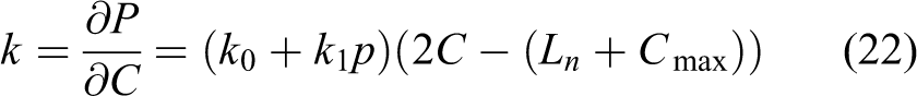
An open-loop impedance controller with model feedforward is selected. 25 This type of force control is called open-loop because there is no force feedback from the device to the controller to regulate the force output of the exoskeleton end effector, as illustrated by the control block diagram in Figure 1. The goal of the model feedforward is to cancel out the corresponding terms in the dynamics of the device. In a quasi-static operation, characterized by low speed, the effects of inertial characteristics and Coriolis and centrifugal terms are neglected and the influence of gravitational effects is taken into account. The feedforward terms for the device stiffness and gravity are included in the control block diagram in Figure 1.

Block diagram of an open-loop impedance controller with model feedforward compensation and natural stiffness specification.
According to this diagram, the controller considers the difference between the desired position deflection ΔXd ≡ Xd−Xo and the actual position deflection of the haptic device ΔX ≡ X−Xo and multiplies it by the desired virtual environment stiffness
The control scheme includes a virtual engine for data transfer between the exoskeleton haptic device and the virtual entity in the virtual scene. This scheme allows the use of two alternative strategies,
26
“patient-in-charge” and “robot-in-charge.” In the “patient-in-charge” case, the subject leads the virtual entity, and the robot follows. The virtual engine, as a virtual spring with low stiffness
In this diagram, the natural exoskeleton stiffness is represented by joint-space stiffness Ke, which is the relationship between the joint torque inputs and the differential angular output. The following relationships can be obtained from the block diagram


Above

represents the desired force command in joint space, calculated in accordance with the desired virtual environment stiffness

Note that Q represents a physical, not control, input to the device. The term Qf in equation (9) represents the force command in joint space as a result of model feedforward compensation. It is calculated in accordance with modeled exoskeleton stiffness in joint space Kef according to the equation

The (h-by-1) vector of equation (9)

is the vector for gravity torques, generated at the exoskeleton joints. Its components

are determined by the mass of links mi, i = 1…n, the gravity acceleration vector in the base frame g0 = [gx, gy, gz] T , and the position vector of the ith link center of mass in the base frame ρi = [ρx, ρy, ρz] T . Substituting equations (11) to (13) into equation (10) and setting ΔXd = 0, without loss of generality, yields

Above,

The goal of the model feedforward stiffness
To adjust the natural exoskeleton stiffness
The desired object compliance
Actuation system, joint stiffness evaluation, and joint torque control
To adjust the natural stiffness of the exoskeleton passively, the actuation system must allow specifying the parameters that determine the stiffness. As mentioned in the introduction, there are a variety of approaches to implement the passive compliance. In the present study, PAMs will be used as adjustable compliance actuators. PAM also has additional advantages such as an excellent power/weight ratio, inherent safety, and low cost.
Self-made braided pneumatic muscles will be used, which allow greater control over the dimensions, forces, and intrinsic compliance. Muscles with a maximum diameter D0 = 0.016 m and a nominal length Ln = 0.390 m will be used. Thus, the created pneumatic actuators will be used not only singly but in a sheaf of several pneumatic muscles (Figure 2). This makes it easy to change the power and stiffness of the actuator. Muscles from one sheaf are fed in parallel with air at a maximum pressure 600 kPa. A supply pipeline is connected with two parallel arranged valves, of which one serves to supply the pressured air and the other for discharging it to the atmosphere. All the muscles of the bundle are connected mechanically at the two ends, where they attach themselves.

Pneumatic actuator composed of a sheave of pneumatic artificial muscles.
Joint motion/torque on the exoskeleton joints is achieved by antagonistic actions through pulleys, driven by sheave pneumatic muscles. Two bundles, a and b, work together in an antagonistic scheme, simulating a biceps–triceps system, to provide the bidirectional motion/force. According to the indications in Figure 3, muscle bundle contraction is defined as the difference between their nominal value Ln and the current value L

Joint actuation with pneumatic actuators working in antagonistic scheme.

while the maximum contraction is defined as the difference between their nominal value Ln and the minimum value Lmin

Braided pneumatic muscle behaves like a pressure-dependent variable compliance spring. For a definition of the used PAM, as a nonlinear quadratic spring, the simplified static model 18 can be used, which is described in the study by Caldwell and Tsagarakis 19 by the following equation

where P is the pooling force of the muscles, Kgas is a muscle geometry-dependent coefficient, p is the operating pressure, and L and Lmin are the muscle lengths according to Figure 2(b). As a result of experiments conducted under static load on the used PAM, in which the number of muscles in a bundle and the magnitude of the supply pressure were altered, it was obtained that at zero pressure, the muscles show elastic properties determined of inner rubber liner. Taking into account this property of the muscles and according to equations (17) and (18), the equation (19) is transformed as follows

Above k0 and k1 are empirically derived coefficients. In the process of approximation, the following relations of the coefficients k0 and k1 have been determined in accordance with the number m of bundle muscles.

Unlike other PAM models, the proposed static model takes into account more parameters such as the number of muscles in the bundle, the current contraction and maximum contraction, and the nominal length of the used muscles and their pressure. The muscle force at zero pressure is also taken into account.
By accepting that the supply pressure is kept at a constant value, the stiffness of the muscle bundle can be determined as a derivative of the muscle force (equation (20)) about muscle contractions or
The stiffness according to equations (20) to (22) is a linear function of pressure and contraction of pneumatic muscles in the bundle, as well as the number of muscles in the bundle. When the muscle bundles move the joint in an antagonistic scheme (Figure 3), the current contractions of each bundle in the joint Ca and Cb are determined by the position q of the driven joint. Muscles are slung over the pulley at the joint, so their contractions depend on the radius of the pulley r. To generate the maximum forces, the muscles are attached to operate with minimum contraction; that is, in one extreme position of the joint qmax, one bundle has zero contraction, and in the other extreme position of the joint qmin, the other has zero contraction. In a current position q of the joint, the contractions of the two muscle bundles are


In each joint position, the sum of contractions (23) and (24) represents the sum of preliminary pretensioning of the two muscle bundles

Then, according to equations (19), (20), (23), and (24), the forces of joint muscle bundles a and b are


According to equations (20) and (22) to (24), the stiffness of muscle bundles a and b is


The joint stiffness can be defined as a derivative of joint torque with respect to joint position

The generated torque in the rotation joint is

where

is the vector of the driving forces in the actuators (26) and (27) and r is the pulley radius. If muscle contractions (23) and (24) are unified in the matrix

after substituting equation (31) into equation (30), it follows that

The derivative of the muscle forces about muscle contractions gives the stiffness of the selected muscle bundles (28) and (29), incorporated in the matrix

The derivative of the muscle contractions (23) and (24), about the joint position, represents a vector with constant components

After substitution into (34), it follows that:

Joint stiffness (equation (37)) is determined by the stiffness of muscle bundles (equations (28) and (29)). When both muscle bundles are different, the joint stiffness depends on the joint position, as well as on the pressure, number of muscles, and preliminary pretensioning of muscle bundles (equation (25)). The stiffness in the joint is realized in the condition of the antagonist equilibrium of forces (equations (26) and (27)) of the two muscle bundles. The antagonistic balance in each joint is achieved by generating control torques (equation (31) in each joint, according to the equality

According to equations (26) and (27), the joint torques are a function of the joint position, as well as a function of the pressure, number of muscles, and preliminary pretensioning of muscle bundles. Joint torques (equation (38)) are set as vector components by equality (9), representing force commands in the control block diagram in Figure 1

According to the selected control algorithm, the pressure pa for actuator antagonists is set by the natural stiffness controller. Joint controllers determine the pressure pb for the actuators’ agonists, using equations (26), (27), and (38) to achieve the required joint force command Q. This can be represented by the function

A control block diagram of the joint torques is shown in Figure 4, as a component of the impedance controller shown in Figure 1.

Block diagram of the joint control.
It is assumed in the block diagram of Figure 4 that when the control torque Q is positive, the actuator a is an antagonist, and the actuator b is an agonist. When the control torque Q is negative, the roles of both actuators and their control are changed—the actuator a is an agonist and the actuator b is an antagonist.
Natural stiffness controller optimization procedure
The natural stiffness controller included in the control block diagram on Figure 1 has the task to adjust the natural exoskeleton stiffness
Exoskeleton stiffness in joint space can be presented by (h-by-h) diagonal matrix Ke f, including joint stiffness coefficients (equation (30))

Its inverse form represents the (h-by-h) compliance diagonal matrix of the exoskeleton in the joint space

The exoskeleton compliance in Cartesian space Be cf can be calculated as a function of the joint compliance Be f and joint positions, involved in Jacobian (equation (5))

This is a (ν-by-ν) symmetrical matrix
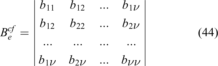
allowing the calculation of the Cartesian stiffness of the exoskeleton by inversion

The goal of the natural stiffness controller is to adjust the natural compliance of the exoskeleton

The symmetrical (ν-by-ν) matrix of the Cartesian compliance
Specifying a complete compliance matrix in most tasks is not necessary. Specification only for certain components of the compliance matrix, for the upper compliance limits in the workspace, or only along a single direction in the workspace is sufficient. Different specification approaches can be created according to the performed task. Searching for a solution by solving the system of equation (46) can yield a negative or unrealistically high value of joint stiffness. The problem can be solved successfully by optimization, solving the task with the limitation of parameters.
The adjusting of the natural stiffness problem can be subjected to solving offline, as it is processed by the impedance controller to compensate the inaccuracies in the offline passive stiffness specification. Offline parameter planning is quite appropriate under the control strategy “robot-in-charge” when the motion trajectory is preliminarily given.
Various optimization methods for the design of robotic devices can be used to solve the problem.
24
It is important the computational costs of the method to be not too high. For this reason, unlike the methods where the multiobjective optimal procedure is used, here a procedure with only one optimality criterion will be created—adjusting the natural compliance of the exoskeleton
If the selected components of the desired object compliance
The compliance is considered as a pressure function in the actuator antagonists pai in the joints of the exoskeleton arm, united in the vector

The pressures in the actuator agonists pbi in the joints are defined by the function (39) of the pressure in the actuator antagonists pai. They are united in the vector

The task can be solved in an optimizing way, finding a zero minimum of equation (47) at the limitation of the parameter values


where pmin and pmax are (h-by-1) vectors including the lower and upper pressure limits of the joint actuators.
The optimization problem is solved by finding a zero minimum of equation (47) with an additional condition composed of equation (39) and set by vector function Φ
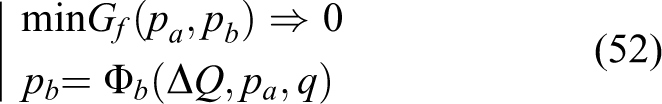
According to this procedure, the natural stiffness controller allows planning of the pressures pa in actuators’ antagonists for adjusting the desired object stiffness.
Computer simulations with a PAM-driven exoskeleton according to the scenario of virtual gymnastics
To assess the capabilities of the proposed natural stiffness controller, computer experiments were conducted. A real PAM-driven exoskeleton was used as a haptic device for applications in virtual reality.
The device, which is developed to function as a powered exoskeleton, is composed of a branched serial kinematics structure, kinematics similar to the structure of the human body, as shown in Figure 5. The kinematics structure consists of four movable bodies 1, 2, 3, and 4 and four rotational joints (Figure 5). The first two rotational joints J1 and J2 are incident and mutually orthogonal to emulate the kinematics of a universal joint with the same center of rotation, such as the human shoulder. The third and the fourth joints J3 and J4 are selected to be two rotational joints incident and mutually orthogonal to emulate the kinematics of a universal joint with the same center of rotation, such as the human elbow flexion and the human shoulder rotation.
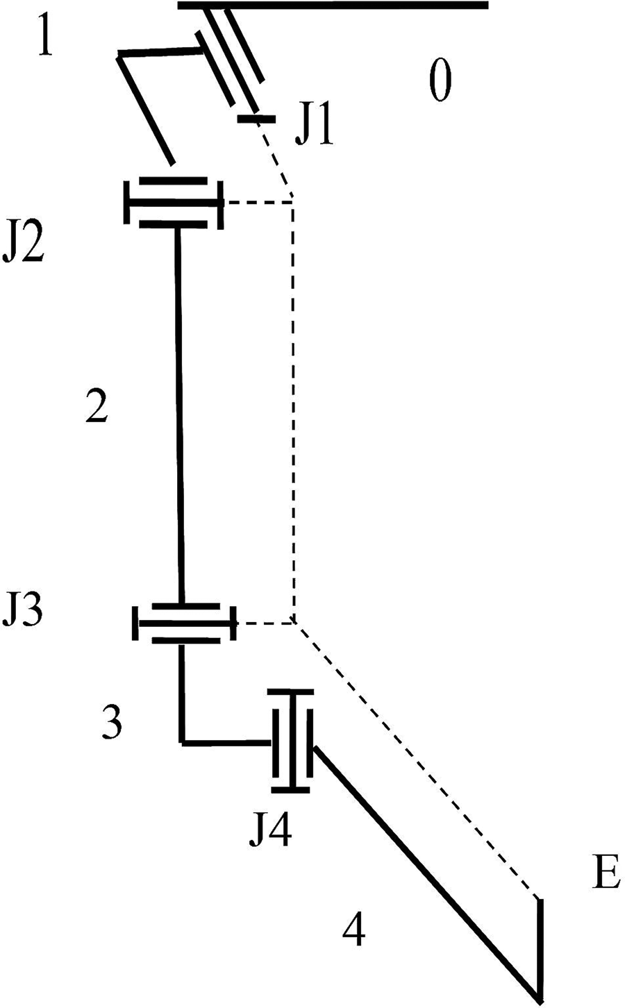
Structure scheme of an exoskeleton arm.
Moreover, the third joint was assumed to be coincident with the elbow joint, as shown in Figure 5. The effective movements of the selected four joints simulate the movements of a human arm in the shoulder and the elbow. The exoskeleton upper limb structure possesses h = 4 degrees of mobility. This structure is chosen to construct an arm exoskeleton, consisting of two equal-type actuated universal joints. Assuming that the operator hand is connected to a point E to the exoskeleton end effector, we will further consider exoskeleton positions only, and we will accept the operation space as three dimensional (ν = 3). The vector of end-effector coordinates (equation (2)) will be (three-by-one) dimensional, and Jacobian (equation (5)) will be (three-by-four) dimensional.
The mechanical structure of the exoskeleton system includes two arms, which are grounded as each arm is built up, according to the structural diagram in Figure 5. The basic parts of the exoskeleton arm structure are made of aluminum. Masses of the exoskeleton arm units are defined using a CAD program. The masses of the four basic units (Figure 5) are as follows: m1 = 0.437 kg, m2 = 0.594 kg, m3 = 0.364 kg, and m4 = 0.434 kg. The lengths of the exoskeleton arm and forearm in the initial setup are as follows: 0.286 and 0.370 m, respectively. The range of motions in joints J1, J2, J3, and J4, respectively, are 110°, 120°, 150°, and 135°.
An application of the exoskeleton as a VR haptics device is further discussed. 3-D Unity Virtual Engine is used for data transfer between the exoskeleton and the avatar in a virtual scenario. Optical tracker, head-mounted display Oculus Rift, is used for visualization of the virtual system and to track the head position and orientation. The exoskeleton is designed to track the position and orientation of the human body and to provide force feedback to the human arm. Figure 6(a) shows the two-armed exoskeleton and the human operator wearing the head-mounted display when embodied in the virtual reality. For example, a virtual gymnastics application is considered. Figure 6(b) shows a scenario of virtual gymnastics—an exercise with fitness rubber bands. The strips are placed between the avatar hand and the fixed support as shown in the diagram of Figure 7. The figure shows four right-hand positions corresponding to positions in computer graphics. Also, the three stiffness ellipsoids for each position are shown, according to the experiments described below. It is important that the end-effector stiffness in the direction of the rubber band corresponds to the value of rubber band stiffness. The desired direction is set by the vector

Application of virtual gymnastics (a) human operator with a two-armed exoskeleton and (b) virtual scene of gymnastics.

Evaluation of the end-effector stiffness at arm positions 1, 2, 3, and 4 according to the experimental cases (a), (b), and (c)

where N is the vector of the coordinates of the point of strip attachment, X is the vector of the coordinates of the arm end effector, and l is the modulus of the vector [N–X] equal to the length of the strip.
The exoskeleton has joints driven by the antagonistic acting bundles consisting of seven PAMs. For the virtual gymnastics scene considered, the muscles achieve the following joint angles [qimax; qimin], i = 1,…,4: [110;0], [110;0], [90;0], and [70;−20]. These angles according to equation (25) define preliminary contractions of the muscles.
Computer experiments were performed to specify the stiffness in the direction of the gum strip. Since the direction is represented by the vector (equation (53)) of single force T (

The inverse form of equation (54) gives the stiffness in this direction

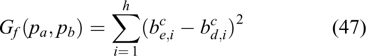
For stiffness specification in the direction of the gum strip, the next goal function is composed of

where
The task is solved by optimization according to equation (52) at the limitation of parameter values (50) and (51), where pmin = 0 and pmax = 600 kPa. Since the number of optimization parameters i = 4 is greater than the number of target parameters μ = 1, the problem possesses many solutions and can be quickly solved. Calculations are performed at four points on the selected trajectory of motion 1, 2, 3, and 4, as shown in Figure 7. Calculations are made considering force commands in the exoskeleton joints (equation (39)) calculated from the gravitational component (equation (14)). The proposed model and optimization algorithm are developed in MATLAB code for conducting experiments.
The experiments were carried out in the following steps:
Setting the lowest pressure of the actuator antagonists. The pressure pai, i = 1,…, 4 of the antagonists is set to 0 and the corresponding driving forces pai are calculated according to equation (26), i = 1,…,4. The forces pbi in the actuators’ agonists b are determined so that they can realize antagonistic equilibrium (38), considering the force commands in the joints. The pressure of actuator agonists pbi is calculated according to equation (27). The stiffness of the muscle bundles kai and kbi in each joint i = 1,…, 4 is computed according to equations (28) and (29) and the stiffness in the joints Kqi is calculated according to equation (37). The compliance of the end effector is calculated according to equation (43). Compliance and stiffness in the direction of the gum strip are calculated according to equations (54) and (55). The stiffness values at the four points of the trajectory, as well as joint positions qi, i = 1,…,4 and strip length l, are shown in Table 1.
Adjusting the stiffness in the direction of the gum strip with a desired value
Calculating the possible maximum stiffness in the desired direction. The actuator agonists are set at the highest pressure pbi = 600 kPa, and the corresponding driving forces pbi are calculated according to equation (27), i = 1,…,4. The forces pai in the actuator antagonists are determined so that they can realize antagonistic equilibrium (38) in every joint considering force commands in the joints. The pressure of actuator antagonists pai is calculated according to equation (26). The stiffness in the direction of the gum strip is calculated as described in case (a). The stiffness values at the four points of the trajectory are shown in Table 1.
Stiffness values in the direction of the gum strip for four points of the trajectory shown in Figure 7.

The results of the experiment according to cases (a), (b), and (c) are presented graphically in Figure 7, where the modeled Cartesian stiffness is represented by an ellipsoid, built by the procedure given by Chakarov.
28
Graphically, the stiffness in the desired direction

Stiffness in the desired direction ke cT and stiffness ellipsoids at the four points 1, 2, 3, and 4 after optimization.
Values of actuator parameters at position 4.

Discussion
The proposed procedure shows that by altering the muscle pressure of a PAM-driven exoskeleton, the end-effector stiffness adjustment can be achieved. The boundaries of this adjustment are defined. The lower boundary is defined by the necessary pressure for gravity compensation, and the upper boundary is defined by the allowable pressure on the muscles.
The simulations carried out according to the scenario of the virtual gymnastics indicate that one can obtain the desired characteristics of the virtual scene stiffness. If the desired object stiffness is within the admissible limits, the optimization procedure defines the appropriate parameter values. Achieving these parameters in the joint controllers generates a natural exoskeleton stiffness equal to the desired value. Deviation of the object from the target will generate an elastic force of the exoskeleton on the operator’s hand. If, due to the delay of the optimization or another reason, the natural stiffness of the exoskeleton is not equal to the desired value, the impedance controller will compensate for this with active stiffness.
If the desired object stiffness is greater than that achievable with the mounted pneumatic drive, the pressure reaches the upper limit as in case (c) of the example shown. The possibilities to reach high values of the desired stiffness in an active or passive way are limited by the capabilities of the actuation used. For this reason, the use of a PAM-driven exoskeleton as a haptics device is suitable only for tasks with a low value of the simulated stiffness. Such tasks are virtual scenes of games, sports, rehabilitation, and others, where humans lead and the exoskeleton performs the assistive functions.
Conclusion
A solution for adjusting the natural stiffness of a pneumatic powered exoskeleton, designed as a haptic device in virtual reality applications, is studied in this work. A control algorithm is built, including an open-loop impedance controller. A natural stiffness controller is added to passively adjust the exoskeleton stiffness to the desired level. The design of the actuation system based on PAMs is revealed, and the solutions for joint stiffness and joint torque control under the antagonistic action of pairs of pneumatic actuators are presented. An optimization-based approach is created for specifying the parameters determining the natural stiffness of the exoskeleton arm. Computer simulations are conducted for an assessment of options for adjusting the Cartesian stiffness. Computer experiments are performed for specifying the object stiffness, according to the scenario of virtual gymnastics.
The originality of this work is, that unlike the known solutions, the proposed control algorithm includes a natural stiffness controller based on an optimization procedure. By calculating the optimal actuation parameters, a natural stiffness is generated that matches the desired characteristics of the virtual scene stiffness. An advantage of the adjusted natural stiffness is the immediate force response and increased safety due to the reduction of the active stiffness. The active stiffness is only used for auxiliary compensations.
Footnotes
Acknowledgements
The authors would like to thank the European Commission through FP7 Integrated Project VERE and by Bulgarian Science Found, Call: 2016, through Project AWERON.
Declaration of conflicting interests
The authors declared no potential conflict of interest with respect to the research, authorship, and/or publication of this article.
Funding
The author(s) disclosed receipt of the following financial support for the research, authorship, and/or publication of this article: This work was funded by the European Commission through FP7 Integrated Project VERE—no FP7-257695 and by Bulgarian Science Found, Call: 2016, through Project AWERON—DN 07/9.