
Abstract
This article reports our research results on an autonomous forklift, with the focus on pallet recognition and localization using an RGB-D camera. It is a fundamental issue for unmanned storehouses, which enables the forklift to insert the forks within the pallet’s slots for loading and unloading packages. Particularly, a pallet recognition and localization approach is presented. The range image is firstly segmented into planar patches based on a region growing algorithm. Then, the segments are filtered heuristically according to the storehouse environment. Afterward, a template matching method is utilized to recognize pallets in the remained segments, based on calculating the degree of similarity at each location during sliding the templates on the segment. Once a pallet has been recognized, its pose is calculated straightforward. The article has three main contributions, that is, a low-cost RGB-D camera is employed for pallet recognition and localization, where only depth information has been utilized; using the proposed method, multiple kinds of pallets can be used at the same time, which provides a flexibility for the storehouse; and furthermore, the method has a good expansibility to allow the storehouse to adopt new pallets easily.
Introduction
Unmanned storehouse is one of the fundamental issues to build the automatic logistics system, which has attracted increasing attention in recent years. 1 –3 In an unmanned storehouse, as an autonomous robot, the forklift has to deal with the basic navigation problems, for example, localizing itself, planing a safe path, and navigating to the goal point. Besides these navigation requirements, pallet recognition and localization is the most important issue, which enables the forklift to insert the forks within the pallet’s slots for loading and unloading packages.
Automation of pallet engagement is not only useful for unmanned forklift. It can also be integrated on manually guided forklifts, thus enabling to load and unload pallets effectively, especially helping to avoid damages caused by operator mistakes.
In this article, we propose an approach for pallet recognition and localization using an RGB-D camera, for example, a Microsoft Kinect 2.0 camera. The proposed algorithms can be also applied to other type of RGB-D cameras. It can also be applied to pure depth cameras since only the depth channel is involved in this study. Compared against existing works (see “Related work” section), the proposed approach has the following advantages. Firstly, there is no requirement for additional modification on the pallet, such as sticking markers on the pallet. Secondly, various kinds of pallet can be recognized and localized at the same time. Particularly, commonly used plastic pallets and wooden pallets have been employed for evaluation. Thirdly, there is no constraint on the environment illumination. Fourthly, the approach has an approximately linear computational complexity, which can be easily parallelized for real-time applications.
As a result, there are two main contributions in this article. Firstly, the approach allows to use multiple kinds of pallets, which means a flexibility for storehouses. Secondly, new pallets can be easily adopted to the system; in other words, the proposed approach has a good expansibility.
To evaluate the proposed approach, a series of tests have been carried out in a simulated storehouse, as illustrated in Figure 1. The pallet localization results have been utilized to guide the forklift to load the pallets with goods. Note that the QR codes fixed on the ground are used as landmarks for the visual navigation system.

Photos of the simulated storehouse, as shown; different kind of pallets are used in the storehouse. The blue lines and QR codes fixed on the ground, which can be seen on the first two figures, are artificial landmarks for the visual navigation system.
This article is organized as follows. The related work on pallet recognition and localization was given in “Related work” section, followed by detailing our planar segment-based approach in “Planar segment-based pallet recognition and localization” section. Experiments and results come in “Experiments and results” section, and the last section concludes this article.
Related work
A number of pallet recognition methods have been proposed in the past years. According to the features being used, the pallet recognition methods can be divided into two categories.
First, approaches based on artificial features (fiducials) are attached to the pallets. In the study by Seelinger and Yoder, 4 three fiducials are placed on each pallet: a white-centered fiducial in the middle and two black-centered fiducials on either side of the pallet; then a vision-based approach has been proposed to identify the fiducials. Two reflectors are fixed left and right on the short side of the pallet in the study by Lecking et al., 5 which are detected using a two-dimensional (2-D) laser range finder (LRF). This approach is independent of luminance conditions. However, the 2-D LRF can only scan a slice of the environment, which requires a prior knowledge of the vertical position of the pallet, if the involved pallet is from a stack. Basically, using artificial features simplifies the problem, at the cost of labeling of all pallets with such features. Additionally, the circulation of pallets among storehouses is very strong, which limits to use them locally. Therefore, to promote these approaches in real storehouses is very difficult.
Second, approaches are based on self-contained features of the pallets, that is, shape, color, and other possible characteristics. For example, Garibotto et al. 6,7 proposed a vision-based algorithm to detect the central holes of the pallet, where the geometry model of the pallet is projected onto the image plane for position estimation. Similarly, Byun and Kim 8 also detect the holes in the image based on monocular vision. However, different from Garibotto et al., 6,7 the geometric model is projected onto a virtual plane which is parallel to but not the image plane. Pagès et al. 9 proposed an image segmentation method based on the color and geometric characteristics of the pallet. For this approach, the camera should be calibrated carefully and a good illumination condition is required. Another work can be found in the study by Walter et al., 10 where a closed-loop pallet manipulation system is proposed. For pallet recognition and localization, closest edges are detected in the region of interest (ROI) of a single 2-D laser scan. However, the ROI should be specified by a remote operator which decreases the automatic level of the system. Baglivo et al. 11 proposed a multisensor fusion method, where a 2-D LRF and a camera have been employed. The pallet is first identified from a one-dimensional model in the laser scan, with a coarse orientation estimation. However, false positives may occur in this step. To omit the false positives and locate the pallet accurately, the candidates are further filtered using the visual information, and the remained positions are optimized based on the geometric model. However, this method requires an accurate laser-camera calibration. Stereo cameras are employed in the study by Varga et al., 12 where a sliding window-based algorithm is employed, and pallet recognition is modeled as a classification problem of the content in the sliding window. In order to classify the content, a boosting classifier based on aggregated channel features is trained. The drawback of this approach is the training phase that requires manually labeled training sets, which is time-consuming.
From the deployed sensor point of view, the abovementioned approaches can be classified into three groups, that is, vision based (including monocular vision and stereo vision), 2-D LRF based, and vision/2-D LRF hybrid system based. Both vision and 2-D LRF have their notable limitations: lighting condition is the main challenge for vision sensors; 2-D LRF can only scan objects in one plane, which introduces difficulties for efficiency. Different from them, the depth channel of RGB-D cameras has a similar field of view as normal CCD cameras and won’t be affected by variant illumination. Therefore, we explore the possibility to use RGB-D cameras for pallet recognition and localization in this article.
For pallet localization in the real storehouse applications, there are actually four degrees of freedom (DoF) to be determined, that is, the three-dimensional (3-D) position plus the yaw angle, as there is no change with regard to the pitch angle and roll angle. Particularly, the accuracy of yaw angle estimation is very important, in order to avoid collisions during inserting the forks into the pallets. If the deployed sensor can provide range information, for example, stereo cameras and LRFs, the localization can be calculated directly from the range information. However, for monocular vision-based methods, pallet localization is usually done by affine transformation.
Planar segment-based pallet recognition and localization
As shown in Figure 1, there are multiple kinds of pallets in the simulated storehouse, which are made of different materials and have different colors. Actually, they also have different geometric characteristics, see Figure 5. However, their end faces share a generality, that is, they are planar.
We assume the goods are carried in boxes (can be large or small in size). Although the boxes may be not aligned well, they still construct an approximate plane, which can be seen in Figure 1. Furthermore, the total width of the boxes is close to the width of the pallet. This is a weak constraint in a storehouse, since most goods are transported in boxes. Especially, the width of goods won’t be too narrow or too wide for the reason of keeping balance and space efficiency.
Based on the abovementioned properties and assumption, we propose a planar segment-based method to recognize and localize variant pallets. The point cloud gathered with Kinect 2.0 is first segmented into planar segments. The segments are then filtered heuristically based on prior knowledge about the environment. Afterward, each segment which may contain a pallet is assigned with a local coordinate system, and the segment is further discretized into a 2-D grid in the local coordinate system, with binary values in each cell indicating whether the corresponding cell has been occupied by the segment. After that, each template slides on the grid to search whether a corresponding pallet presents in the segment. If yes, the pallet pose is further determined by back-projecting the matched area to the 3-D space. See the following subsections for detail.
Coordinate systems definition
There are several coordinate systems involved in this article, that is, the forklift coordinate system, the forks coordinate system, the local coordinate system for each potential segment, and the image coordinate system for the pallet template and the segment. Below, an introduction to the first three coordinate systems is given. The local coordinate system and the image coordinate system will be described in “Template matching-based pallet recognition” section.
For clarity of presentation, we note the forklift coordinate system as C
r
, the forks coordinate system as C
f
, and the Kinect camera coordinate system as C
k
. The default Kinect coordinate system has not been used in this article; instead, C
k
is defined in Figure 2. C
f
is defined in Figure 3. C
r
has the same orientation as C
f
. Therefore, there is only a translation vector

The Kinect camera coordinate system.

The forks coordinate system.
In order to guide the forklift to engage pallets, the pallet has to be localized in both C r and C f , which requires the relation between them and C k . In other words, the external parameters of the Kinect camera have to be calibrated.
Since the relation between C r and C f is known, we only calibrate the camera with regard to C f . To make the calibration easy, the Kinect is mounted with its x-axis parallel to that of C f . In this case, the position and the pitch angle have to be determined. For this purpose, the position of the Kinect camera with regard to the origin point of C f is measured manually. In order to get the orientation of the Kinect camera, the forklift is drove to the front of a wall, with the y-axis of C f orthogonal to the wall. Then, a plane is fitted to the wall in the point cloud using RANSAC, whose normal direction can be used to calculate the pitch angle of the Kinect.
Point cloud plane segmentation
Plane detection in 3-D point clouds is a complex task which has attracted increasing attention from both the computer graphics and robotics community in recent years. 13 –15 In this article, the hybrid region growing (HRG) algorithm 16 is employed for plane segmentation. For the sake of completeness, a brief introduction is given here, please see the original article for detail.
The Hessian form equation is chosen to represent planes in this article. It is described as

where
As the name indicates, HRG is a region growing algorithm. As subwindows are employed for efficiency, the algorithm can only deal with organized point clouds which has an image-like data structure for the nearest neighbor searching. HRG processes a given organized point cloud Ψ as follows. It is decomposed into subwindows according to the image-like data structure. Thereafter, the subwindows are classified into planar, nonplanar, and sparse based on the corresponding scatter matrix. After appearance classification, planar subwindows are then put into a list Ω and the other subwindows are put into another list Θ. When there are still unidentified planar subwindows, the subwindow ω with the minimum plane fitting error among all unidentified planar subwindows is chosen as a new seed. A growing region G is initialized by ω, and its unidentified neighbors are put into a first in last out queue Q. Then, G is extended by investigating its neighbors. If the neighbor subwindow is planar, it will be directly determined whether to be added into G. Otherwise, each point in the subwindow will be investigated separately. This process will continue until no new neighbor of G can be found. The algorithm ends when every point has been assigned to a planar segment or not.
During the region growing phase, suppose that ωc is the neighbor subwindow being investigated. If its appearance is planar, it is assigned to G if it meets the following criteria: The dot product between the normal vectors of ωc and G is greater than δ. Actually To avoid adding a subwindow which is parallel but not coplanar to G, the distance from the mass center of ωc to the optimal plane of G should be less than γ. To guarantee an acceptable flatness of the resulting segment, the plane fitting error e of
Otherwise, each point in the ωc will be investigated separately, and a point pc will be added to G if it passes the distance and fitting error test in the above criteria.
After plane segmentation, each point cloud can be represented as an indexed planar patches using a set of plane parameters

Segments filtering
There are many planar surfaces other than the pallets and boxes in the storehouse, foe example, ground, wall, and pillars, see Figure 1 for example. Since the pallet recognition algorithm has a relative high computational complexity, it will be helpful if some prior knowledge can be used to filter out the unconcerned segments. For this reason, the following heuristic cues are applied. In normal cases, the end faces of the pallets should be orthogonal to the ground. In other words, the surface normal should be close to the ground plane. Since the orientation of the RGB-D sensor is known, the angle between the surface normal and the ground plane can be easily computed. In this work, if the angle is larger than a given threshold, the corresponding segment would be filtered out. The width of the segment should be similar to a pallet. Therefore, We detect the left and right edge points of each segment. Then, RANSAC
17
is chosen to fit a 3-D line for each edge. Note that, although the line is in 3-D, they are in the same 2-D plane as they are from the same planar segment. A typical result is illustrated in Figure 4. Afterward, the width of the segment can be estimated based on the two line equations. In the end, if the resulting width is very different from the width of the pallet, the corresponding segment is filtered out.

Segment edge detection and line fitting. The segments have been colored randomly, and the line is shown in blue.
Template construction
For each kind of pallet, the scale parameters are measured, as shown in Figure 5. The end face is then discretized into a grid whose cell size is 1 cm. The grid is represented as a binary image, where the cells are set to 1 occupied by the pallet. The left cells which correspond to the hole of the pallet are set to 0. For example, the binary image corresponding to pallet in Figure 5(e) is illustrated in Figure 6.
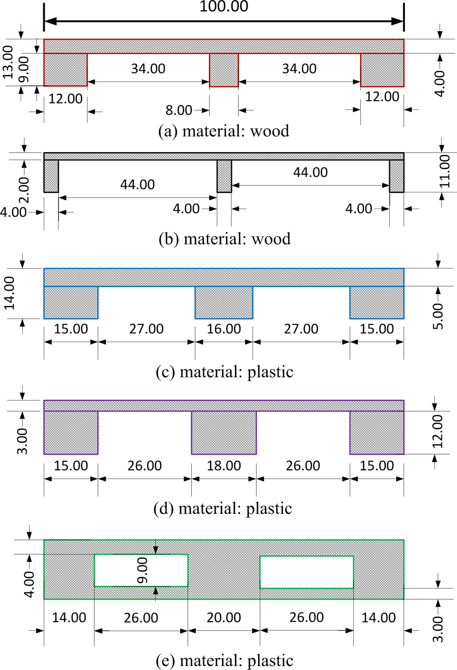
Pallets have been used in this article, with different appearances with regard to their end faces. The scale parameters are represented in centimeters. (a) Material: wood. (b) Material: wood. (c) Material: plastic. (d) Material: plastic. (e) Material: plastic.

The binary image corresponding to the pallet in Figure 5(e).
Template matching-based pallet recognition
After segment filtering, each potential segment P
i is assigned with a local coordinate system Ci, with its z-axis along the surface normal, x-axis parallel to the horizontal plane of the storehouse at the same time orthogonal to the surface normal, and the y-axis is determined by the right-hand rule. There is no constraint on the origin point for Ci, because the z-coordinates are omitted for template matching. Therefore, only a rotation matrix

where
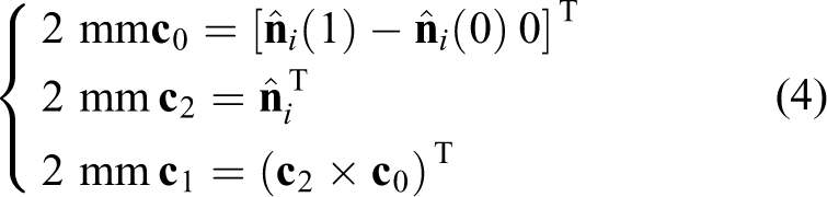
In equation (3) and (4), ⁁ stands for a unit vector, and × stands for the cross product operator.
After obtaining the rotation matrix, all points on the segment are transformed from the Kinect coordinate system to the local coordinate system. Ideally, all points on the segment should have the same z coordinates; however, due to sensor noises, they form an approximate normal distribution around the fitted plane.
The rotated segment is then discretized into a grid with the same cell size as the pallet using a similar behavior, that is, the cells which are occupied by the segment are set to 1, while the others are set to 0. The z coordinates are omitted in this step. A typical discretization example has been illustrated in Figure 7 as a binary image, where 1 is represented as white and 0 is represented as black.
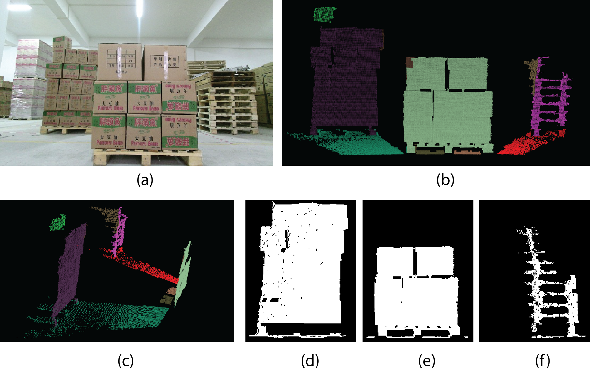
A typical example for segment discretization. (a) The color image corresponding to the processing point cloud data. (b) and (c) The plane segmentation result shown with different view angles, and the segments are colored randomly for better visualization. (d) to (f) The three remained segments after segments filtering, which have been assigned with local coordinate systems and discretized into 2-D grids, are represented as binary images for the purpose of visualization. 2-D: two-dimensional.
Then, every discretized pallet slides on the discretized segment; at each location, the following value is calculated to measure how the underlay patch of the segment looks like the corresponding pallet

where χ represents the degree of similarity between the template and the current patch. In equation (5), θ is the percentage of the number of identical pixels between the template and the current patch compared against the number of all pixels in the template, and μ is the percentage of the number of white pixels compared to the number of all pixels in the template. Based on this metric, the false positive of recognizing a black patch or a white patch as a template can be avoided, since both the black part and white part of the template and patch have been considered.
The maximum χ for each template is found during the above sliding process; at the same time, the position of the patch which reaches the maximum χ is marked. If only one pallet is employed in the storehouse, the next step is to determine whether the resulting patch belongs to the pallet. Otherwise, we pick up the largest χ among all templates and only the corresponding template enters the next step.
A threshold for χ is pretuned to decide whether the current patch is recognized as the pallet corresponding to the involved template. In this article, the threshold is manually tuned, which is time consuming. However, for further study, it could be determined using machine learning methods, such as boosting 18 or SVM, 19 based on manually labeled data sets.
Pallet localization
Once a pallet has been recognized using the abovementioned template matching method, its position and orientation is calculated using the following method. Assuming the recognized pallet is from

The yaw angle β of the pallet in the Kinect coordinate system is derived as

where
Experiments and results
The system setup and conducted experiments are presented in this section. The system will be further benchmarked in our future research.
System setup
To construct an autonomous forklift prototype, a Kinect 2.0 RGB-D camera has been mounted on the top of the carriage of a Komatsu electric forklift, which means the RGB-D camera will move along with the forks, as shown in Figure 8. The electric system of the forklift has been modified, whose motions can be controlled both manually by the driver or via an onboard computer. A laptop is used as the onboard computer for rapid development, which will be replaced with an industrial computer. For self-localization, printed QR codes are fixed on the ground, whose locations are measured manually. A web camera is then mounted on the rear top of the forklift, which is used to recognize and localize the QR codes. In order to see the pallets on the ground, the RGB-D camera looks down at about 10°.

The autonomous forklift prototype, which is modified from a Komatsu forklift truck.
The algorithms have been implemented in C++ for evaluation and all the experiments are carried on an Intel Core 2 Duo 2.53 GHz, with 4 GB RAM under Ubuntu 14.04. Libfreenect2 (open source drivers for the Kinect for Windows v2 device, available at http://github.com/OpenKinect/libfreenect2) is used as the driver for Kinect 2.0. The efficiency of linear algebra is crucial, especially for calculating the eigenvalues and eigenvectors of a matrix, since it has to be performed every step of HRG. Therefore, the Eigen library 20 has been employed. Furthermore, the open source point cloud library (PCL) 21 is employed for 3-D visualization.
Data preprocessing
Different from the structured light technology in Kinect 1.0, Kinect 2.0 uses ToF for measuring depth, which delivers more accuracy depth information. However, the data are still very noisy compared to LRFs. Therefore, the data have to be filtered before processing. For this purpose, a statistical filter implemented in PCL is applied, with a typical result shown in Figure 9.

A typical result of sensor data filtering.
Plane segmentation
As mentioned in “Point cloud plane segmentation” section, there are several parameters in the HRG algorithm, which has to be tuned for each kind of range sensor. In this article, the parameters in Table 1 have been used for the Kinect 2.0 RGB-D camera.
HRG segmentation parameters for the Kinect 2.0 RGB-D camera.

Two typical scenarios and the corresponding segmentation results are shown in Figure 10. It can be seen that the major planar surfaces could be segmented using the HRG algorithm. The average segmentation time is 49.3 ms.

Two typical scenarios and the corresponding segmentation results. The segments are colored randomly for visualization.
Pallet recognition
According to the Kinect camera technique specification, the sensor works well in the range of 0.5–4.5 m. The autonomous forklift prototype has two forks of 1.2-m long, which means the pallet should be recognized when the pallet is further than 1.2 m in order to guide the forks. Furthermore, based on the QR code-based visual navigation system, the path planning modular can control the forklift to a proper position and orientation such that it is in front of the pallet. Therefore, the pallet recognition algorithm works from 1.2 m to 3.5 m from the pallet. The threshold for χ in the experiments is 0.6, which is manually tuned.
Some typical pallet recognition results are shown in Figure 11. For visualization purpose, the patch being recognized as a pallet has been colored as red in the figure. As can be seen, the approach can deal with multiple kinds of pallets, although their end faces have different appearances (see “Template construction” section). The algorithm can also recognize the pallet which is put on other goods, as illustrated in Figure 11(c) and (d). Furthermore, the algorithm can recognize multiple pallets in one point cloud, as shown in Figure 11(e) and (f). The precondition is that the pallet should be fully observed in the point cloud. Otherwise, such as what shown in Figure 11(a), the two partially observed pallets cannot be recognized.
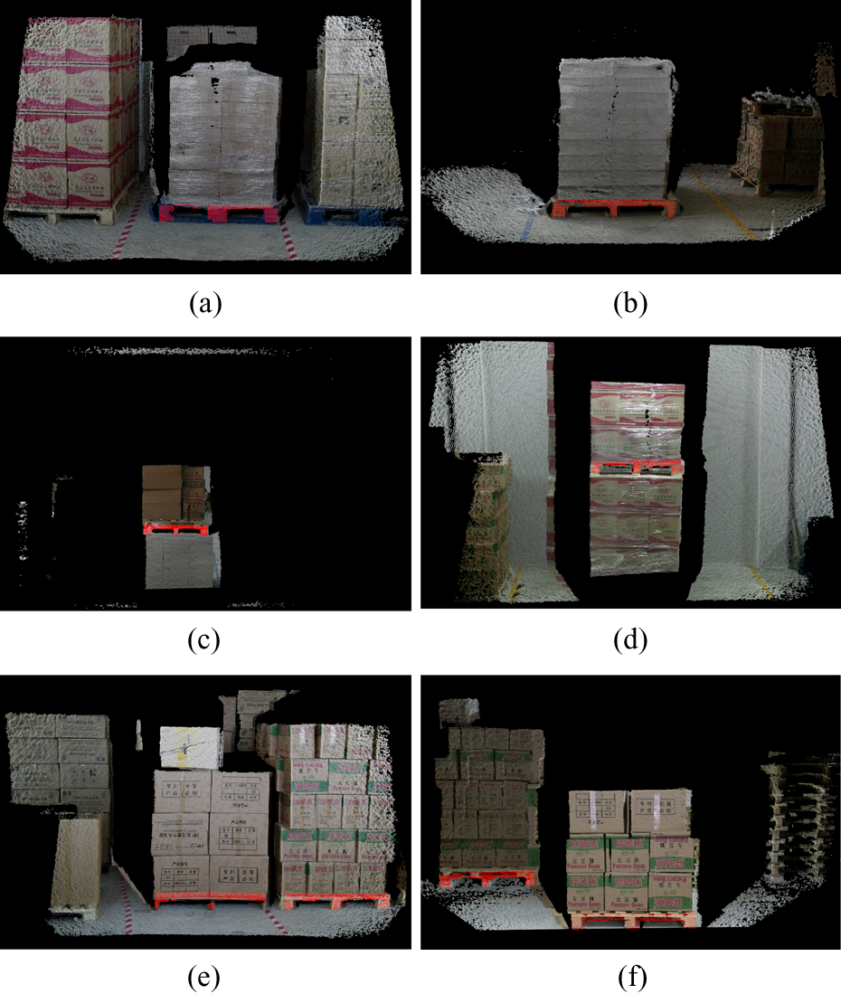
Some typical pallet recognition results, where the patch being recognized as a pallet has been colored red. As shown, the proposed algorithm can deal with multiple kinds of pallets and pallets on other goods.
However, there are some exceptions shown in Figure 12. Actually, the scenario in Figure 12(a) is the same as Figure 11(e). From the experimental results, the left pallet cannot be stably recognized. It is made of wooden, and its color is much darker than others cause of rotten. Therefore, a part of it will be missed in the range information, which results failure recognition cases. We call this exception as “solid part missed.” The pallet in Figure 12(b) cannot be recognized due to a distinct reason. It can be seen that the pallet has been encysted together with the goods by plastic membranes. As a result, the hole of the pallet is filled in the point cloud. We call this exception as “hole filled.”

Pallet recognition failures. The left pallet in (a) cannot be stably recognized because the pallet color is too dark due to the underlay wood is rotten, resulting data missing in the range data. The pallet in (b) cannot be recognized as its hole is filled by plastic membranes.
In the current implementation, about 33 ms is required to search the pallet for each potential segment. In most cases, there are less than three potential segments in one point cloud. In other words, the maximum time spend for pallet recognizing is 100 ms. It should be noted that the template matching process can be easily parallelized for further optimization.
Pallet localization
As mentioned above, the pallet is localized in the Kinect camera coordinate system; however, the result is used to guide the forks operation and forklift motion control. As there is no motion capture system with high accuracy in the simulated storehouse for obtaining the ground truth of pallet localization. The localization accuracy is then tested with guiding the pallet engagement. To make the evaluation easier, we eliminated the complex motion control from the engagement. For this purpose, the forklift is manually driven to the front of a pallet. In this case, the forklift can insert its forks by only going forward with little turnings and adjusting its forks, where the forks has two DoFs, that is, the up ⇔ down motion and left ⇔ right motion.
The experiment is then to insert the forks to the pallet slots automatically based on the pallet localization result. After each experiment, the bias from the forks’ end point to the middle of the pallet slots is measured as the localization error. Please note that, the forks motion control error has also been included in the measured bias. Even though, the maximum bias along the horizontal and vertical direction is below 0.03 m. Since angle is difficult to measure, the yaw angle estimation error has not been evaluated yet. However, the accuracy is enough for pallet engagement, as well as keeping the balance of goods.
Conclusion and discussion
In this article, we have presented a novel pallet recognition and localization approach. The range image is firstly segmented into planar patches based on a hybrid region growing algorithm. Then, the segments are filtered heuristically based on prior knowledge about the environment. Afterward, a template matching method is utilized to recognize pallets in the remained segments, based on calculating the degree of similarity at each location during sliding the templates on the segment. Once a pallet has been recognized, its position and orientation is calculated straightforward.
The article has three main contributions, that is, a low-cost RGB-D camera has been employed for pallet recognition and localization, where only depth information has been utilized. Using the proposed method, multiple kinds of pallets can be used at the same time, which provides a flexibility for the storehouse. Furthermore, the method allows the storehouse to adopt new pallet; in other words, it has good expansibility.
However, there are limitations in this study. Firstly, the accuracy of pallet localization has not been benchmarked. In real-world applications, it is coupled with the accuracy of forklift control, including the wheel movement control and the fork motion control. Secondly, the color channel of the RGB-D camera has not been employed yet, which is helpful for pallet recognition. Thirdly, the thresholds for segment filtering and pallet recognition are still manually tuned, which is time consuming. Furthermore, as Kinect has been employed, the proposed approach currently can be used indoor only.
Therefore, in the future, we will try to fuse the depth channel and color channel for pallet recognition, benchmark the localization accuracy using a motion capture system, and get the thresholds based on machine learning algorithms.
Footnotes
Declaration of conflicting interests
The author(s) declared no potential conflicts of interest with respect to the research, authorship, and/or publication of this article.
Funding
The author(s) disclosed receipt of the following financial support for the research, authorship, and/or publication of this article: This work was supported by National Science Foundation of China (no 61503401 and no 61403409) and China Postdoctoral Science Foundation (no 2014M562648).