
Abstract
This article deals with testing the algorithm developed for autonomous control lock of the differential in a truck. Hardware for hardware in the loop testing of robotic systems or automotive systems is used and the proposed control algorithm was implemented into it. The system was applied to a vehicle with 8 × 8 drive and control algorithm evaluates input sensor values to set robotic console control. It is an actuator which consists of electrovalve, pneumatic cylinder, console, special dog clutch and feedback limit switch. This robotic console is used to lock the truck differentials. Verification of the correct algorithm operation was performed by manoeuvres and the response of the whole system was monitored. The aim was to get the reaction times of this mechatronic robotic system and evaluate them.
Introduction
Autonomous systems are increasingly being used in many areas of technology, such as robotics, automation and automotive. They are mechatronic systems that independently control machines without any human influence. They are characterized by the use of intelligent control algorithms for autonomous behaviour, sophisticated electronics and technologically sophisticated mechanical elements. In the development phase, the autonomous systems should be validated, that is, before the first electronic control unit (ECU) prototype is made. Therefore, it is suitable to use efficient development tools and procedures. These include model in the loop (MIL) and hardware in the loop (HIL) testing. In the latter case, this is a special hardware used to replace ECU. By uploading the control algorithm into the hardware processor, the developed autonomous system can be controlled. 1,2
This article deals with the use of such hardware for the testing of developed autonomous mechatronic system for trucks. However, first it is necessary to verify the control algorithm already during the phase of its sub-assemblies or assemblies with the use of MIL testing. It assumes finding the greatest number of errors. In the second phase, the algorithm is placed in the special hardware for HIL testing that was running on the vehicle. Using this hardware, the inputs were monitored and the actuators controlled on the vehicle without the use of an ECU prototype that can be developed in parallel. These procedures and tools are described in the following chapters. The main objective of this article is to describe the HIL testing of the control algorithm on the vehicle and, primarily, to monitor the reaction times of the differentials lock and unlock. This is the time since the control signal was dispatched by the autonomous control system upon receipt of the feedback from the limit switch on the robotic console. From the results of the measured reaction times, a further optimization of the autonomous system can be determined.
The developed control algorithm is designed for autonomous differentiation lock of the trucks. However, there is a possibility to use a manual control of this mechatronic system. The system is designed for vehicles up to 8 × 8 drive, but the algorithm is modular, so it is easy to extend it to other special vehicle powertrains. The basic concept is inspired by the Automatic Drive-Train Management (ZF ADM) system. 3 In the developed autonomous mechatronic system, the speeds of the individual wheels are monitored and the slip between them is evaluated. In conjunction with other sensors located on the vehicle, an evaluated signal is sent to lock or unlock the powertrain individual differentials. This system automatically controls the drive of the vehicle through the terrain, where it could get stuck without the intervention of the intelligent algorithm. For conventional trucks without an autonomous differential lock system, higher fuel consumption and possible vehicle extrication expenses can be predicted. Therefore, this system is mainly developed for vehicles in heavy terrain where this problem can often occur.
Control algorithm
The control algorithm is designed for the autonomous control of the locking of truck differentials. It is divided into two main sections for autonomous and manual control. The basis is to monitor the individual wheel speed of the vehicle and to evaluate the slip between them. The slip is also evaluated between the powertrain shafts, because this slip may occur earlier than between the wheels. Other sensors are located on the pedals. In the control algorithm, the brake pedal limits the differential lock during braking, the clutch pedal maintains the current state when the gear changes and the braking by engine is determined by the accelerator pedal. In this state of braking, differentials should be unlocked in terms of driving vehicle stability. The steering mechanism of vehicle is equipped with an angle sensor which is important for the calculation of the slip correction when cornering. In this case, different wheel speeds occur, and the algorithm would evaluate the status for locking the individual differentials without necessarily having to. Therefore, the calculation of the slip correction when cornering is included in the algorithm. The control algorithm contains a number of parameters for a control algorithm that evaluates input signals from sensors or Controller Area Network (CAN) communications. If the control algorithm determines that the relevant differential should be locked, it sends the signal to the robotic console. It is an actuator consisting of an electrovalve, a console, pneumatic cylinder, dog clutch and a limit switch. The signal from the control algorithm changes the state of the electrovalve to open and releases the compressed air into the pneumatic cylinder. Because the pressure in the cylinder increases, the piston with the console moves and connects the specially designed dog clutch in the differential. This means that the individual differential is locked. By moving the console, the feedback of the limit switch, which informs the control algorithm of the successful locking of the differential, is switched on. This will allow the progress algorithm to the next state in the scheme of Figures 1 or 2. The pressure sensor is used to check the correct pressure in the pneumatic circuit which is used for pneumatic cylinder. If the conditions for locking different differentials persist, the algorithm proceeds in the diagram and locks the following differentials.
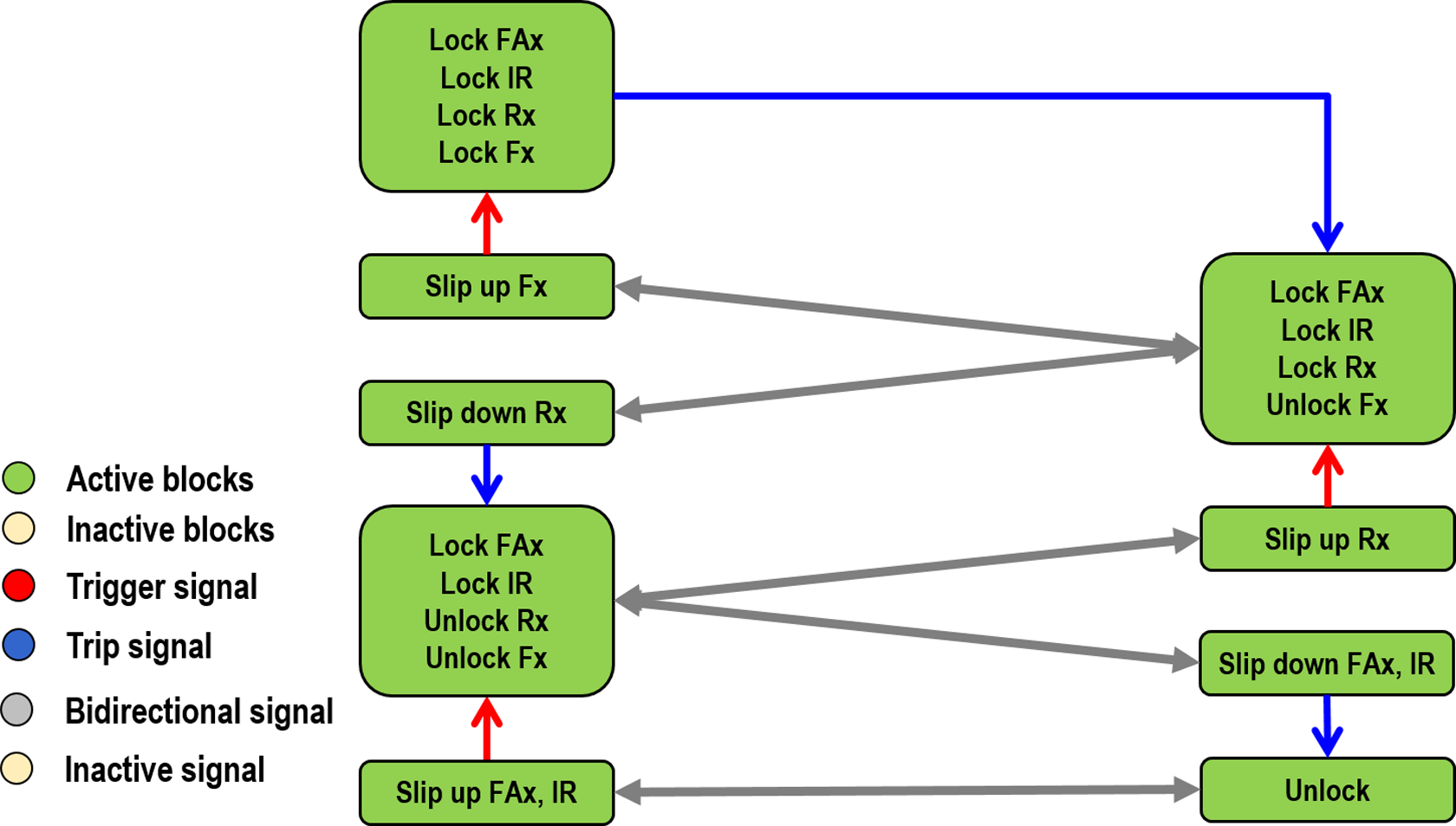
Basic scheme of control algorithm for dependent control.

Basic scheme of control algorithm for partly independent control, vehicle with 6 × 6 drive.
The algorithm is designed for the two operation schemes shown in Figures 1 and 2. The first scheme is for dependent control. This means that all-wheel drive (Lock FAx, Lock IR) is activated in the first phase. In the second phase, the rear axial differential (Lock Rx) is locked and front axial differentials (Lock Fx) are locked in the last phase. Figure 1 shows the slip up and slip down blocks, which check whether the algorithm is actually moving or staying in the current position of the scheme. The second scheme is for partly independent control. In the first stage, all-wheel drive is activated. In the second phase, the differential lock is controlled independently and the diagram is further subdivided into independent subgroups. For both schemes, if they reach the end of the scheme and all the differentials are locked, it is not how to evaluate the state for unlocking the differentials. For this reason, a test loop is included in the algorithm that unlocks an appropriate differential and checks input parameters. The algorithm evaluation resets the lock or proceeds in the scheme to unlock all the differentials and deactivate the all-wheel drive. The schematics may vary according to the distribution of the powertrain and the number of wheels; therefore, the algorithm is modular. Then it can be adjusted for different powertrain configurations without any major adjustments. The algorithm is written in C language and then compiled into the appropriate format for MIL and HIL testing or the prototype ECU.
MIL testing of the algorithm
The developed control algorithm should be tested prior to implementation into the ECU prototype. There are various sophisticated tools and procedures for MIL testing. This involves creating a loop between a computational model and a control algorithm. In this case, the computational model of the vehicle and the autonomous control system for differential lock of the truck are connected. This method makes it possible to detect the majority of mistakes and thus to prevent failures and unexpected situations of the control algorithm.
The computational model of the vehicle is composed of blocks in the Simulink software [version 2012]. These blocks are part of their own developed library 4 –6 and represent different parts of the powertrain or the whole vehicle. They are engine blocks, clutches, transmission, tyres, dog clutch, differentials, axles, brakes, vehicle dynamics, to name but a few. These blocks are based on the mathematical models described in literature, 7 –10 The user can build a complete vehicle with various modifications of the powertrain and then simulate different manoeuvres, analyse vibrations or test control algorithms for mechatronic systems. An important aspect of computational models for MIL testing of the developed algorithm is the possibility of simulation of slip between individual wheels. Therefore, the tyre blocks are based on the 11 equations and the tyre-to-road adhesion parameters are external inputs in the block. The value of these inputs is generated by the road block depending on the vehicle position and the defined areas with different adhesion characteristics. In this way, the user defines different terrains with varying coefficients of the rolling resistance and adhesion. When simulating, the vehicle passes through the set terrain and there is a slip between the wheels generated. Output from the model is wheel speed, pedal position, steering angle, to name but a few. These outputs correspond to the required inputs for the control algorithm. The state of the vehicle is evaluated and, if the differential needs to be locked, the algorithm sends the signal to the actuator. In the computational model of the vehicle, the actuator is included in the differential block or in the block to activate the all-wheel drive. Upon receipt of the signal, the computational model of differential begins simulating the differential lock and sends feedback on its successful lock. Then the algorithm evaluates the next current state and decides where to move the scheme further. Figure 3 illustrates the computational model of the vehicle with 4 × 4, 6 × 6 and 8 × 8 drive in a loop with a control algorithm. This article focuses on HIL testing; therefore, specific simulations will not be described here but some of them are published in the study by Kučera and Píštěk. 12

Computational model of the vehicle in the loop with control algorithm for MIL testing. MIL: model in the loop.
The C control algorithm was implemented in the Simulink software environment using the S-function. 7 It was then linked to the required inputs and outputs of the computational model of the vehicle. During this testing phase, errors in the control algorithm can be found without compromising the driver. Therefore, MIL testing was an important procedure in developing a new control algorithm for the differential lock of the truck.
HIL testing of the algorithm
In order for the control algorithm to be applied to the vehicle, the hardware for HIL testing is used. In this case, hardware by National Instruments NI 3110 RT was used. The device is located in the vehicle cabin. It is shown in Figure 5. Its main part is the processor where the developed control algorithm was implemented. This hardware serves as an ECU replacement. An advantage is the parallel development of the ECU prototype and the simultaneous testing of the developed control algorithm on the vehicle. The NI 9159 slot for the input and output modules NI 9229, NI 9239, NI 9425 and NI 9472 and the CAN communication card were connected to the hardware. The slot includes a programmable field programmable gate array (FPGA). The FPGA is used for communication of main hardware with input and output modules, as well as to implement own code. The control algorithm was compiled from C language to a suitable format to be implemented with NI VeriStand software [version 2013] in processor memory.
The algorithm was tested on a vehicle with 8 × 8 drive. The basic parameters of the vehicle are the wheelbase 2150/2860/1450 mm, track 2074 mm, the weight 38,000 kg and tyre 16.00 R20. The parameters of its air-cooled V-engine are number of cylinders eight, displacement 12,700 cm3, engine power 325 kW at 1800 r/min and engine torque 2100 Nm at 1000 r/min. The vehicle powertrain is divided into four axles and the rear two axles are driven permanently. The basic setting of the vehicle is 8 × 4 drive and the drive of all axles can be activated by special dog clutch designed by the vehicle manufacturer. These dog clutches are also used in their differentials. However, these will not be described in detail in this article, because it is the know-how of the truck manufacturer and its part of the development of a mechatronic system for automatic differential lock control. The powertrain also includes a rear inter-axle differential and axle differential for each axle. On the test vehicle, each differential or actuation of all axles drive has an actuator. This is connected to the signals from the control algorithm and the pneumatic circuit. The actuator, or the robotic bracket, consists of an electrovalve, a console pneumatic cylinder and special gear clutches. Also included is a feedback limit switch which sends information about the correct differential lock.
The electrovalve was controlled by HIL testing using the digital output module NI 9472 and the feedback was connected with the digital input (DI) module NI 9425. Other sensors on the vehicle were the speed sensors in each wheel that were connected to the analogue input (AI) module NI 9229. Because they are the inductive sensors, it was necessary to process the sine signal and evaluate the wheel speed. This is a fast process, because FPGA was programmed in the NI 9159 slot for this purpose. Data from the sensors were processed and the speed of each wheel was evaluated. These wheel speeds were passed to an algorithm that runs already in a much slower loop. Programming was done using NI LabVIEW software [version 2013]. The steering wheel and pressure sensor in the pneumatic circuit were connected to the AI module NI 9239 and the pedal sensors were connected to the DI module NI 9425. The hardware was also connected to the CAN communication for control of the engine torque.
The mechatronic vehicle system was tested on specially shaped road. During this, the axles are relieved and there is a slip between the wheels, which is shown in Figure 4. From the sensors mentioned above, the algorithm autonomously evaluated the current state and controlled the actuators without driver intervention.
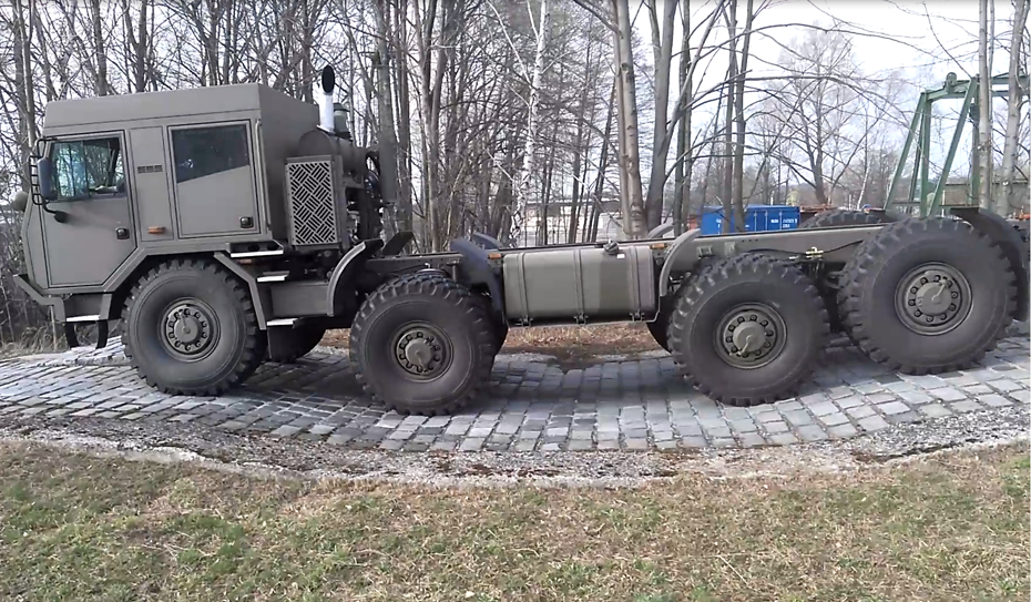
Tested vehicle.
Figure 5 shows a user-programmed graphical interface for the developed system in the monitor of the notebook. The user can set parameters of the control algorithm in this interface and monitor the input, output, internal variables and error messages of the algorithm. The graphical interface was programmed in NI LabVIEW software and placed in workspace of NI VeriStand software, which is used to communicate and to place the control algorithm and also to communicate with all peripherals. In these tests were monitored the correct function of the mechatronic system, optimized control parameters and also the reaction times of the individual differential or the activation of the all-wheel drive. Reaction time analysis presented in the next chapter is the aim of this article. Some of measured data are shown in Figure 6. The figure shows the locking or the unlocking states of the individual differentials and their feedbacks.
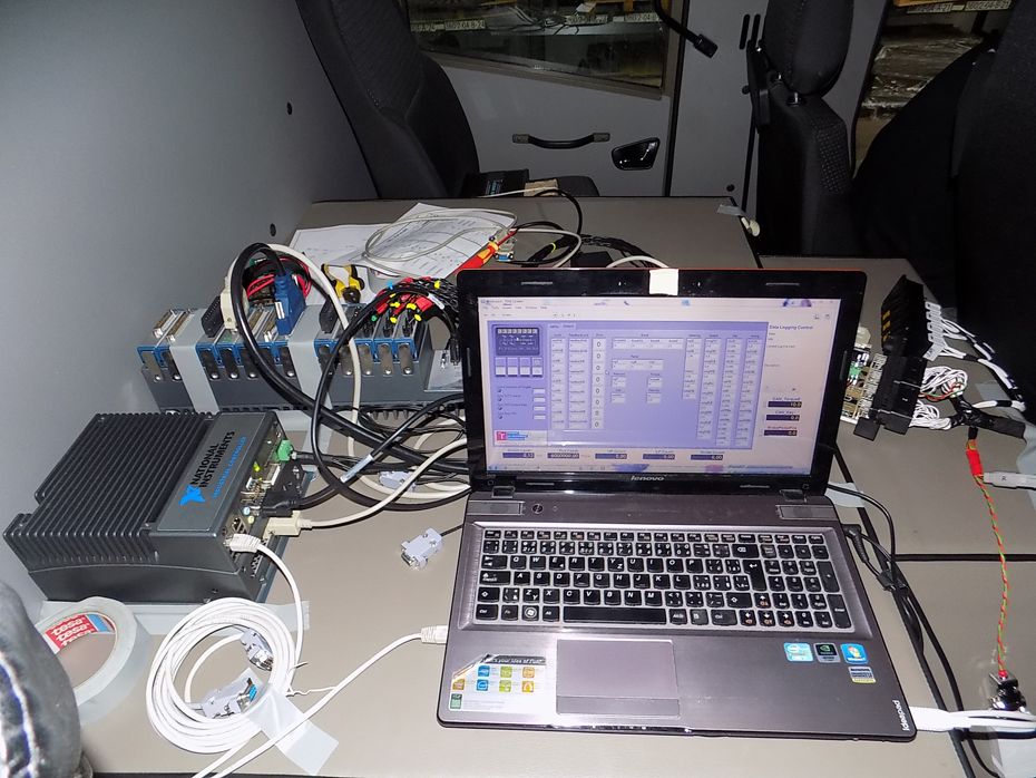
HIL connection and user graphical interface. HIL: hardware in the loop.
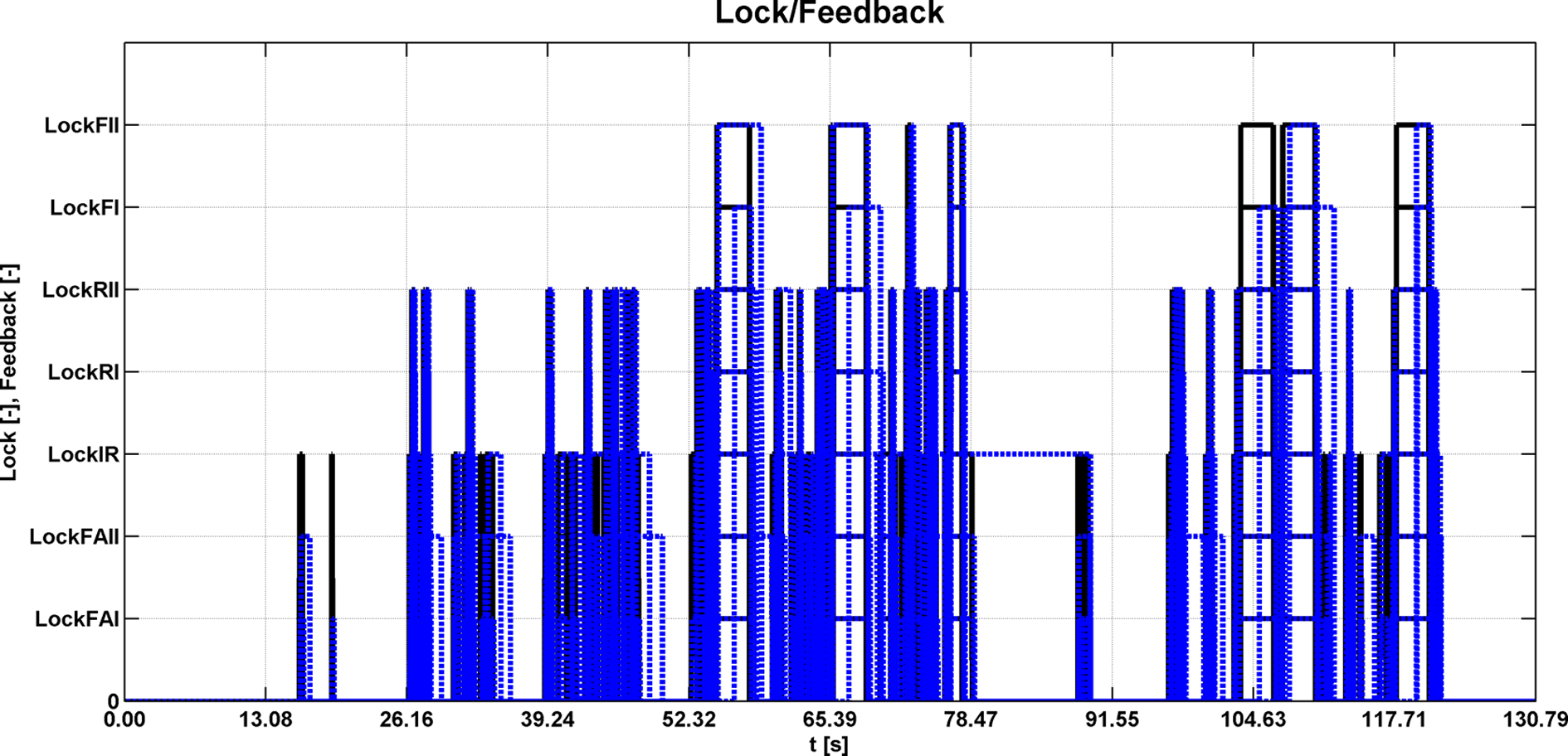
One of measured data for lock and unlock status of the individual differentials and their feedback.
Analysis of the system reaction time
Using HIL testing, input, output and variable data were obtained during the driving manoeuvres. The data are designed to analyse the correct behaviour of the autonomous mechatronic system and also to analyse the reaction time of the differential, and this will be the main focus of this chapter.
This time response is important from the point of view of the functionality of the whole system, because the differential cannot be locked at high different wheel speeds. Then, the destruction of the parts of the powertrain could occur. This problem is evaluated in the control algorithm, and if the wheel speed difference is above the specified limit, the individual differential must not be locked. Despite these measures, it is important that the reaction times are as small as possible, because the dog clutches could still generate shocks that would not result in the destruction of the parts of the powertrain but it would be uncomfortable for the driver.
Measurement of the differential lock reaction times was evaluated using the MATLAB [version 2012] software in which a data analysis script was built. The monitored response time was always evaluated from the signal change of the individual differential lock to the received information about differential lock or unlock from the feedback limit switch. This time includes the function of the robot console and hardware for HIL testing. It is a hardware reaction time that is negligible, the time of the electrovalve switching, the time of the pneumatic and mechanical parts and the feedback time of the feedback limit switch. The evaluation of the time is performed for seven actuators designed to activate the drive of all axles (Front axle I - drive activation of the axle (FAI), Front axle II - drive activation of the axle (FAII)), to lock the rear inter-axle differential - lock the rear inter-axle differential (IR), to lock two axial differentials of two front axles (Front axle I - lock axial differential (FI), Front axle II - lock axial differential (FII)) and to lock two axial differentials of two rear axles (Rear axle I - lock axial differential (RI), Rear axle II - lock axial differential (RII)). The setting of the feedback limit switch and dog clutches was different in order to evaluate the correct setting for short locking or unlocking times of the differentials. The data were obtained on two shaped roads and 10 measurements were taken for each. In these obtained data, the minimum, maximum and mean times for the lock and unlock of the individual differentials were monitored. Furthermore, these values from the individual measurements were averaged and are shown in Table 1.
Reaction time of differential lock and unlock.

It follows from the table that the average differential lock time is about 0.26 s and the unlock differential is 0.42 s. First of all, it is necessary to focus on the locking times of the differential so that the vehicle does not get stuck in heavy terrain due to longer reaction. The results show that some settings for the individual differentials or activation of the drive of all axles were very fast and somewhat slow for some. This means that setting the non-electric part of robotic console will have a significant effect on the reaction time; therefore, the hardware response is much shorter. The time for the differential unlock is important in terms of the condition when the individual differential should not be locked. In this case, excessive strain on the components of the powertrain may occur, for example, when cornering. Another test procedure will be the setting of other actuators according to the one that had the shortest reaction time to lock and unlock of the differential. Subsequent measurements and testing will be performed on different driving modes and road types.
Conclusion
For rapid development of autonomous mechatronic systems, it is necessary to use different tools. These include MIL and HIL testing, and these can be used for parallel development and testing of the control algorithm and the ECU prototype in a very efficient way.
This article explored the use of hardware for HIL testing and evaluation of the reaction times for locking or unlocking the individual differentials or activating the drive of all axles. As part of the development, a control algorithm for autonomous differential lock control was designed and tested during development. Therefore, MIL testing was used and the vehicle computational model and the control algorithm were simulated in a loop. Subsequently, hardware for HIL testing was used and the control algorithm was placed in its processor. With this tool, the mechatronic system could have been tested on the vehicle and the proper functioning of the whole system was analysed. In this article, vehicle testing was primarily focused on the observed response time of differential lock and unlock for various actuator settings. The results have shown that some settings have a reaction time of about 0.1 s, which is capable of competitiveness.
The next step is to set actuators according to those with the shortest response and an extensive testing on different types of roads. The aim will also be to analyse whether reaction times can be shortened. This would make the behaviour of the whole mechatronic system as comfortable and efficient as possible for driving on different types of roads.
Footnotes
Declaration of conflicting interests
The author(s) declared no potential conflicts of interest with respect to the research, authorship, and/or publication of this article.
Funding
The author(s) disclosed receipt of the following financial support for the research, authorship, and/or publication of this article: This work is an output of NETME CENTRE PLUS research activities (project no LO1202) and is funded by the Ministry of Education, Youth and Sports under the ‘National Sustainability Programme I’ and of internal BUT research project reg. no FSI-S-17-4104. The support from EU Structural Funds provided within the framework of project no CZ.1.05/2.1.00/19.0397 NETME Centre TechUp is also gratefully acknowledged.