
Abstract
The actual dynamical development of the information technologies is also typical for the area of automotive industry. The autonomous control technology is moving the motorcars into the mobile robot category. The autonomous mobile robotic vehicles, together with new possibilities offered thanks to the mobility services, are improving not only comfort but also safety of transport. Nowadays, application of the homogeneous charge compression ignition technology represents a great progress made in the field of internal combustion drive, taking into consideration more and more rigorous emission standards. This article deals with principles and architecture of the autonomous control, with hybrid drive systems as well as it analyses advantages of the homogeneous charge compression ignition technology, taking into consideration the obtained experimental results.
Introduction
Every innovation technology is primarily evaluated with regard to its progressive functions. One of the innovative, advanced technologies is also the autonomous vehicle control, which is moving the motorcars into the category of mobile robots and probably represents just a future development trend in the modern transport area.
More and more stricter emission limits encourage progress of the electro-mobility as well as expansion of the hybrid drives. The HCCI technology belongs to the very perspective systems and innovative technologies especially in the mobile robotics area 1,2 with regard to the future development trends.
Autonomous control
In case of ordinary vehicles (i.e. the standard motorcars), the vehicle user or driver is making the key decisions and controlling the vehicle according to the information obtained from the external surroundings.
The autonomous vehicles are operated without the intervention of the user, except setting of the final point as a target destination of the vehicle trip. Various sensors and control systems are applied that are installed in the autonomous vehicles instead of the driver’s participation. Figure 1 illustrates an ordinary vehicle with the human user and the autonomous vehicle equipped with the sensors and vehicle control system.

Ordinary and autonomous vehicle.
It is evident according to Figure 1 that a design proposal of the autonomous vehicle control systems requires to determine how the external obstacles will be sensed and how the vehicle will be moving from the starting point taking into consideration the random decisions during riding. 3 The following diagram (Figure 2) represents the principled architecture of the autonomous vehicle design.

Principled architecture of the autonomous vehicle.
The main functions of the autonomous vehicle can be divided into the following items: identification of an obstacle by means of the proximity sensor, vehicle navigation using the GPS system, control of engine by the ECU (IC engines) or control electric drive by the drives PWM (battery-powered) and steering control, for example, with servo-drives.
Drive of the autonomous vehicle
Drive of the autonomous vehicle is usually ensured by means of the internal combustion (IC) engine or the vehicle is battery powered. While the IC system requires combustion of a fuel in the engine combustion area, the battery-powered vehicle is not equipped with the piston combustion engine 4,5 because it is exploiting electric energy, which is stored in the accumulators that are supplying one or more driving electromotors. The electromobiles represent an alternative solution to the standard vehicles because they are able to produce the driving torque immediately and their acceleration is more fluent compared to the vehicles equipped with the IC engine. Relation of the electromobiles to the environment is not so explicit in such a case when the electric energy, which is used for charging of accumulator, is delivered from the coal power plant. 6,7 Another complication is the limited endurance distance per one accumulator charging. Taking into consideration the above-mentioned facts, it is possible to say that nowadays there are always predominant IC engines in the automotive industry. 8 It is a well-known fact that the actual emission limits concerning the IC engines are very hard and from this reason there is arising a serious problem for the automobile factories to meet the demanding emission requirements. Development of the new, improved engines and application of the anti-emission measures are connected with very expensive investments, moreover with a doubtful future. 9
The possible solution offers application of an innovative technology, which is denoted as homogeneous charge compression ignition (HCCI). 10 The HCCI technology is based on a combination of the gasoline engine, which is using the spark ignition, with the diesel engine utilizing the compression ignition. This integration of two different ignition principles into one combustion engine combines the best characteristic feature of both ignition systems. A gasoline is applied as a fuel, however, with a higher engine indicated efficiency, which is typical for the diesel engine.
The engine indicated efficiency depends on the compression ratio (CR) and on the ratio of the specific heats γ = cp /cv , Figure 3. 11,12

Indicated efficiency of the SI engines, diesel engines and HCCI engines. SI: spark ignition; HCCI: homogeneous charge compression ignition.
Combustion of the homogeneous charge is running all at once in the whole piston combustion area, that is, the charge is combusted almost completely, without a rest. Exploitation of the gasoline using the HCCI technology is very efficient and it offers a significant reduction of the fuel consumption, together with the reduced exhaust gas emissions, whereas the NO x emission is almost neglecting. However, application of the HCCI technology is connected with some basic problems, for example, there is a high level of pressure values during compression, high thermal loading during combustion process and a control of the self-ignition process is complicated. 13
The prestigious automotive companies (e.g. the General Motors, Mazda, Mercedes Benz or Hyundai) are currently developing the HCCI technologies. The existing problems concerning the diesel engines confirm a legitimacy of such development. Application of the HCCI technology, together with the most modern motor-management components (direct fuel injection, variable valve timing, etc.), enables to reach saving the fuel and fulfilment of the future emission rules. Efficiency of the piston combustion engine equipped with the HCCI technology is similar to the diesel engine efficiency, however, without a necessity to apply an expensive system, which is required for elimination of the NO x emissions. Efficiency of the system is based on fuel combustion using lower temperature levels and on reduction of heat losses together with decreased carbon dioxide emissions.
The piston combustion engine based on the HCCI technology can be successfully applied not only as a driving unit of the standard motorcars 14 but it can also be used as a driving unit of the electric generators installed in the hybrid drives of the motorcars (Figure 4).

Hybrid drive of a motorcar.
Principle of the HCCI technology
A principle of the HCCI-engine operation using combustion of the gasoline–air mixture is already known during a longer time period. This technology offers a suitable possibility for increasing of the gasoline engine efficiency so that it could be similar to the diesel engine efficiency. The self-ignition process is passing all at once in the whole piston combustion area. There is an important advantage of low costs required for exhaust gases cleaning during the application of the HCCI technology. The gasoline–air mixture is ignited due to a self-ignition process after compression of the charge. However, application of the ‘classic’ spark plugs is still necessary, especially in the case of cold engine starts as well as during a high-load operational regime. If the engine works with low-level loading, the controlled homogeneous charge compression ignition is just activated. The specific fuel consumption of the piston combustion engine, which is equipped with the HCCI technology, is similar to the diesel engine–specific fuel consumption, however, without a necessity to apply an expensive system, which is necessary for the elimination of the NO x emissions.
Figure 5 illustrates a dependence of the pressure inside the cylinder on the crank angle for 500 sequential combustion cycles within the HCCI regime. There is also a visible transition regime where the fuel mixture is ignited by the sparking plug during the stable combustion of the HCCI. Figure 6 illustrates a dependence of the in-cylinder pressure on the crank angle for 150 sequential engine cycles during the stable regime HCCI.

Dependence of the in-cylinder pressure on the crank angle for 500 sequential combustion cycles within the HCCI regime. HCCI: homogeneous charge compression ignition.
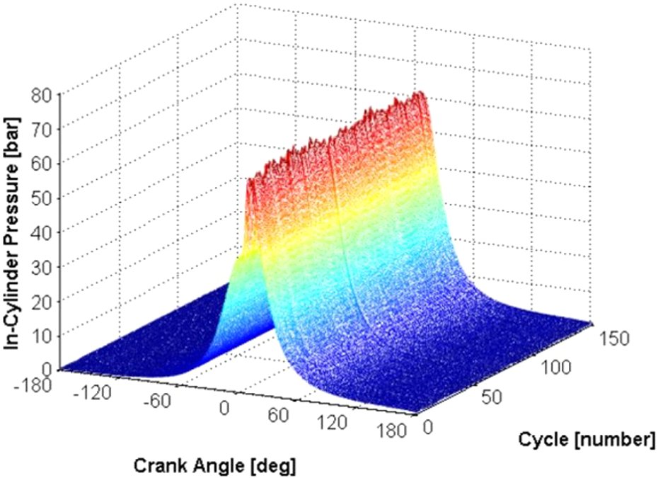
Dependence of the in-cylinder pressure on the crank angle for 150 sequential engine cycles during the stable HCCI regime. HCCI: homogeneous charge compression ignition.
Application of the HCCI technology
The main problem within real application of the HCCI technology is a fact that a process of the fuel mixture self-ignition is difficult with regard to its control ability. It is possible to reach the HCCI regime in the case of the standard combustion engine during a short term using the process of data editing from the pre-ignition map and fuel map. However, the problem is occurring if the engine temperature conditions are changing because in such a case the HCCI regime is unstable and there is arising a possibility of the serious engine construction damage. 15 –18 Therefore, the main task of this article is a conversion of the common gasoline IC engine in order that it will be able to operate in the stable regime HCCI. The testing engine is a gasoline, single-cylinder, four-stroke engine equipped with the fuel direct injection and it has increased the CR 19:1. The fuel injection system is a product made by the company Ecotrons. The electronically controlled throttle valve regulates the engine speed by throttling of the air intake.
A heat control system was developed as shown in Figure 7 in order to perform a conversion of the engine so that it can be operated in the HCCI regime. This system controls temperature of the gases entering the cylinder, and in this way, it controls the self-ignition process as well. The intake air is flowing through the throttle valve. Consequently, the fuel is injected into the intake air, and the created fuel–air mixture is passing through the compressor. After the compression process, the compressed fuel–air mixture is divided into two streams: one stream is ‘hot’ and the second stream is ‘cold’. The hot flow is passing through the heat exchanger and it is warmed-up by means of the exhaust gases. The cold flow is passing through the cooler. Both the streams (the hot stream and the cold stream) are separated, that is, they are flowing separately. The engine cylinder is equipped with a mixing valve in order to combine both the streams, and in this way, the distributor regulates the temperature during suction into the cylinder. The temperature regulation valve is controlled by means of a computer using the electric servomotor.

The testing engine (left) and the heat control system.
The feedback signal is obtained from measuring of the cylinder pressure every 0.5 crank angle degree (CAD). Analysis of the cylinder pressure performed during measuring of the released heat determines the combustion timing, which is defined as such crank angle, by which there is released 50% of the heat (CA50). The calculated combustion timing is applied as the feedback, which enables controlling of the combustion process by means of the temperature regulation valve. The installed software is processing all the sensed data as well as it is controlling the whole system (Figure 8).

Global architecture: the sensors and software.
Minimization of the fuel consumption
It is possible to define for the given operational point, which is characterized by the engine speed and torque, a specific time moment of ignition with the minimal fuel consumption. This optimal timing is a compromise among the active work obtained from the mixture combustion, the heat transfer losses and the combustion efficiency. If the combustion process is starting before piston position in the top dead centre (TDC), thus expansion of hot gases, together with the reduced cylinder volume, causes a rapid increase in the cylinder pressure and temperature. In this way, the piston movement is hindered. Moreover, high temperature is increasing the NO emissions and too high in-cylinder pressure is able to damage the engine. 19 –21
Furthermore, if the pre-ignition is rising, there is also at disposal a longer time for heat transfer and vice versa, if the ignition moment is closer to the TDC, the in-cylinder pressure and the cylinder temperature are reduced, and the active work of the gas is lower. In this case, reduction of the in-cylinder pressure and the cylinder temperature is able to cause an incomplete combustion. An optimal combustion timing is defined for every engine operational point as a compromise among all the above-mentioned influences. Prediction of the optimal combustion timing is a complicated task due to many contradictory processes and therefore it must be determined experimentally. From this reason, the extremum seeking (ES) control can be used as a helpful tool in order to accelerate this process. The ES is useful for selecting the required unknown values that are optimizing a non-linear performance indicator. The fuel consumption is used as the indicator of performance in this article, and the ES serves for determination of the required combustion timing value, which minimizes this indicator. According to Figure 9, the ES is used for minimization of the fuel consumption of the HCCI engine by tuning the required combustion timing value. Combustion timing (i.e. the output value) is very sensitive to the intake temperature (the input value). In this case, the discrete ES version specified for minimization of the cost function is applied, which is quantifying the performance of the controller. The costs are functions of errors between the actual and the required combustion timing. The controller parameters are being actualized online, using an optimization process. This method does not require additional calculations and it reduces significantly the time, which is necessary for selecting the controller optimal parameters, namely using the proportional–integral–derivative (PID) controller. The PID controller compares the required combustion timing value with the measured combustion time of the HCCI engine. In this way, the control signal intended for a reduction of the difference between both the above-mentioned time values is generated. This difference reduction is realized by a position of the valve determined for the intake air temperature regulation. The physical principle of the given method is based on the analysis of the in-pressure values, which is performed during measuring of the released heat.

Application of ES for the HCCI engine in order to minimize the fuel consumption. ES: extremum seeking; HCCI: homogeneous charge compression ignition.
In order to minimize the fuel consumption, the cost function in the ES is applied. The cost function consists of the average fuel consumption per 100 engine cycles

where n is the engine cycle,
The ES was applied in the case of the testing HCCI engine at the engine speed level 1500r/min (Figure 10). The engine speed and engine loading are constant during the fuel consumption tuning. The invariable black line in Figure 10 is set up so that it will be actualized by means of the ES after every 300 engine cycles.

The ES minimizes the fuel consumption by deceleration of the combustion timing from 3 to 8 CAD ATDC using the more conservative parameters. ES: extremum seeking; CAD: crank angle degree; ATDC: after top dead centre.
Figure 10 illustrates a relevant fact that the ES decelerates the combustion timing up to the value 8 CAD after TDC (ATDC) compared to the initial combustion timing 3 CAD ATDC. The delayed combustion timing causes a reduction of the fuel consumption. Duration of the optimization process was approximately 30 min, that is, about 50 repeats according to the horizontal axis in Figure 10.
The analogical experiment was realized using the same working model, however, with a higher value of the adaptation benefit. In this case, the ES determined the identical minimum, but much faster (Figure 11).

The ES minimizes the fuel consumption by deceleration of the combustion timing from 3 to 8 CAD ATDC faster using more aggressive parameters. ES: extremum seeking; CAD: crank angle degree; ATDC: after top dead centre.
According to the analysis of the obtained results, it is evident that the ES is shifting the ignition time about 6 CAD later and in this way, it reduces the fuel consumption by more than 10%.
Application of drones for autonomous robotic vehicles
The autonomous robotic vehicles represent an application area of the drones, as well. The drones can be equipped with the navigation systems determined for an automated control of the vehicle trajectory and supported by a video-based navigation. The drones enable to obtain the long-recording snap sequences or the 3D modelling of various objects and processes. The drones applied in the area of the autonomous vehicles are able to guide the autonomous robot, to scan the terrain and obstacles as well as to evaluate the possible risks. 22
Authors of this article are dealing with building of the special vehicle prototypes specified for the annual international competition Shell Eco marathon in London. This race is organized by the company Shell and it is focused on the minimal fuel consumption of the vehicles. Application of the autonomous control, together with utilization of the presented HCCI technology in the new experimental prototype (Figure 12), will be another relevant step in the technological development and in minimization of the fuel consumption.

The multicopter DJI Phantom 2 and the experimental vehicle.
Another innovative technology should be the application of a drone, which is specified for guiding the experimental vehicle in order to monitor the terrain and to evaluate the possible risks. The results obtained from the drone’s mission, that is, the photos or video records, will be analysed consequently.
During the experiment, the multicopter DJI Phantom 2 Vision+ (Figure 11) will be used. This UAV equipment belongs to the category of the ‘cheap’ UAV. It has a built-in GPS, a compass, gyroscope DJI and HD camera with a resolution of 14 megapixels. The camera is located on the three axial gimbals, which ensure its stability by means of three DC motors.
Conclusion
This article analyses the present state of a mutual conjunction of the motorcars with the mobile robotics in order to reach a significant progress in the transport area.
The autonomous vehicle control substitutes a human factor of the vehicle user or driver, and in this way, it improves safety and reliability of the vehicles. Even a better effect is expected after implementation of a drone for the vehicle guiding and control.
The hybrid drives or the HCCI technology described in this article determines the future development trends in the automotive area thanks to their positive influence on the fuel consumption and on the emission reduction. These innovative technologies probably represent a future in development and in design of the modern vehicles.
Footnotes
Declaration of conflicting interests
The author(s) declared no potential conflicts of interest with respect to the research, authorship and/or publication of this article.
Funding
The author(s) disclosed receipt of the following financial support for the research, authorship, and/or publication of this article: This work was supported by the Slovak Research and Development Agency under the contract No. APVV-16-0259. This article was written in the framework of Grant Projects: APVV-16-0259 “Research and development of combustion technology based on controlled homogeneous charge compression ignition in order to reduce nitrogen oxide emissions of motor vehicles”, VEGA 1/0198/15 “Research of innovative methods for emission reduction of driving units used in transport vehicles and optimisation of active logistic elements in material flows in order to increase their technical level and reliability” and KEGA 041TUKE-4/2017 “Implementation of new technologies specified for solution of questions concerning emissions of vehicles and transformation of them into the educational process in order to improve quality of education.”