
Abstract
Positive position feedback control is the most common resonant control technique that has been studied for last three decades. As a low-pass filter, positive position feedback is very sensitive to low-frequency disturbances. To overcome this shortcoming of positive position feedback controller, negative derivative feedback controller, which acts as a bandpass filter and can effectively control the lower and higher frequency disturbances, has been developed recently. So far, there is no comparison work between positive position feedback and negative derivative feedback on flexible manipulator system. Consequently, to fill this gap, in this article, both positive position feedback and negative derivative feedback controllers are applied experimentally and analysed in terms of settling time and vibration attenuation at different damping ratios on a single link flexible manipulator featuring piezoelectric actuator. Moreover, robustness with respect to natural frequency variation is studied for the first time on flexible manipulator system. Based on experimental study conducted on the particular system developed in this article, it has been observed that negative derivative feedback controller is more effective than positive position feedback controller based on evaluated performance measures.
Keywords
Introduction
Flexible manipulator offers a large number of advantages over rigid manipulators. These include faster response time, lower power requirement, lower cost, high payload-to-weight ratio and so on. 1 These advantages have urged the use of flexible manipulators in industry and space application. However, despite all these advantages, they are susceptible to severe tip vibrations. These vibrations should be eliminated or at least reduced for accurate and fast execution of task. Several vibration control techniques have been applied to flexible manipulator system during the last two decades. 1 –3
Siciliano and Book applied single perturbation approach to control flexible manipulator system. 4 The main idea was to separate the two dynamics, that is, rigid joint motion and elastic link motion and then designing different control laws for both dynamics. H∞ control has also been applied, which describes the control problem as a mathematical optimization problem and then finds appropriate controller for its solution. 5 Intelligent controllers such as neural network 6 and fuzzy logic 7 have also been considered for vibration control of flexible manipulator system. The other control techniques used to control flexible manipulator system include input shaping technique, 8 output redefinition, 9 stable inversion in time domain, 10 optimizing independent motion of flexible arms 11 and so on.
In many flexible structures, only a few vibration modes are significant, so vibration can be controlled by controlling only certain number of modes. In these situations, resonant control techniques are appropriate solution to vibration problem. In these techniques, a first- or second-order dynamic system (compensator) is used to apply control force on the system. Some state-of-the-art resonant control techniques include active modal tuned mass damper (AMTMD), positive position feedback (PPF) control, integral resonant control (IRC) and negative derivative feedback (NDF) control. IRC is one of the novel techniques developed recently, 12 and it takes advantage of pole-zero interlacing property of collocated sensor–actuator pair to damp vibration modes. This property ensures that the phase of a collocated transfer function lies between 0° and −180°. However, to satisfy this condition, only collocated sensor–actuator pair should be used, this design constraint is not practically feasible in certain applications. Recently, AMTMD has been introduced, 13 which uses passive TMD formulation to define a resonant controller and then finds the control force from its equation. One of the oldest resonant control methods is PPF control and it was introduced to control vibration of large flexible space structures. 14,15 In PPF, control structural position coordinate is sent as an input to the compensator, and the product of the compensator’s output and gain is fed back to the structure in a positive sense to act as a control force. Shan et al. applied PPF algorithm to control the vibration of a single link flexible manipulator. 16 Lately, NDF control has been introduced. 17 It works on feeding the velocity of structure to compensator and then feeding back the compensator velocity multiplied with some gain to the structure in a negative sense.
There are numerous advantages associated with PPF controller, such as it is insensitive to spillover, its magnitude rolls off quickly at high frequencies, it is relatively easier to apply in real-world situations and its stability can be ensured by adjusting only the stiffness properties of the structure. 16 Despite these advantages, PPF is very sensitive to low-frequency disturbances as it works as a low-pass filter and hence it causes a worsening of system behaviour below the natural frequency. On the other hand, NDF works as a bandpass filter and eliminates both the higher and lower uncontrolled mode effect; therefore, it avoids low-frequency worsening and it is more robust to spillover effects. So far, there is no direct comparison work between PPF and NDF on a single link flexible manipulator system. Consequently, the main contribution of this work is to compare vibration control performances of PPF and NDF via implementation on a flexible manipulator featuring smart piezoelectric actuator, where vibration is induced due to slewing manoeuvre of the flexible arm. Furthermore, in order to enhance the practicality and feasibility of these techniques in real-world environment, robustness (with respect to natural frequency variation) of the controllers has been experimentally performed, studied and compared. Moreover, in the previous research regarding NDF control, 17 compensator damping ratio was kept equal to the system damping ratio, while in this research, compensator damping ratio is considered as a controlling parameter which ensures more flexibility of design under different operating conditions. In this process, the effect of compensator’s damping ratio on controller’s performance has been evaluated. Moreover, both controllers are compared in terms of settling time and vibration attenuation. Hence, a comprehensive performance evaluation of controllers is provided.
As far as the application fields of these controllers are concerned, they mostly have been applied to suppress vibration of flexible beam. Author believes that these control techniques can be further applied to suppress vibration in aircraft wings and other flexible structures. Large flexible space structures and space inflatable structures are also one of the key applications of such techniques, where PPF and NDF controllers can be used to control structural vibration. Since these controllers work on resonant control, therefore, they can be applied to control sound waves as well.
This article is organized as follow. In ‘Resonant control technique’ section, PPF and NDF control schemes are discussed in detail providing physical insight especially in the case of NDF controller. Experimental set-up and results are discussed in ‘Experimental set-up’ section along with further investigation of the controllers. Finally, conclusion is included in the last section.
Resonant control technique
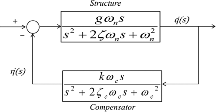
The working principle of resonant control technique is very simple, and it produces a damping effect on particular vibration modes by applying a control force that is opposite in phase to the velocity of structure at the resonance frequencies under consideration. Figure 1 shows the block diagram of resonant controller. Here, ‘q’ is the response of the structure, that is, sensor output and ‘η’ is the output of the compensator.

Block diagram of resonant controller.
PPF control
PPF is one of the widely used controllers in active vibration control area. To explain its working principle, consider a single degree of freedom system which is basically a single decoupled mode as shown in the following equation

where ζ and ωn
are the damping ratio and natural frequency of the structure, respectively. g is the plant gain,

where ζc and ωc are the damping ratio and frequency of the compensator, respectively, and k is the compensator gain. Figure 2 shows the control scheme of PPF method. In single degree of freedom form, PPF introduces a second-order compensator, which is derived by the position response of the structure. The position response of the compensator multiplied with some gain and square of natural frequency is then fed back to give the force input (voltage input to piezoelectric actuator) to the structure.

Control scheme of PPF controller. PPF: positive position feedback.
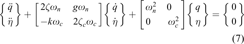
In order to find the stability of PPF controller, combining equations (1) and (2), placing them in their second-order form and assuming no external forces give 18

Goh and Caughey 14 and Caughey 19 used Routh Hurwitz criteria to determine the stability conditions of PPF controller, while Fanson and Caughey 15 used Liapunov’s approach to find the stability criteria of PPF controller. Applying Liapunov’s approach to equation (3), one can guarantee PPF stability as long as stiffness matrix is positive definite, that is, the eigenvalues are all positive, which gives

Hence, PPF controller will remain stable if the product of gains is positive. The transfer function of PPF controller is given by
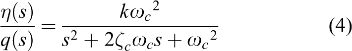
Figure 3(a) and (b) shows the Bode plot of PPF controller at ζc = 0.2 and ζc = 0.6, respectively. In present analysis, ωc value is taken equal to the first natural frequency of the system which is equal to 7 Hz and ‘k’ is taken as 1. It can be seen from Bode plot that PPF is generally a low-pass filter whose magnitude rolls off at higher frequencies. If we look deep into the phase angle plot, we can notice that our controller is providing −90° of phase with respect to the input at resonant frequency. As our system equation has same characteristics as our controller equation, it will also provide −90° of phase with respect to its input at resonant frequency, so the combined effect of compensator and system will result in −180° of phase at the control frequency. This signal is then positively fed back to the system thus providing the cancelling effect.

Bode plot of PPF controller. (a) ζc = 0.2. (b) ζc = 0.6. PPF: positive position feedback.
Moreover, in Figure 3, the magnitude of resonant peak shows that how much force we are applying on the structure through piezoelectric actuator, and the higher the magnitude at resonant frequency the greater is the applied force and vice versa. On the other hand, the slope of the phase angle tells us about the robustness of the system. Robustness is the ability of the controller to attenuate vibration satisfactory even if there are discrepancies between the actual natural frequency and the calculated one. Steeper slope indicates that the phase angle value is varying rapidly around resonant frequency; in this case, if there is slight error between the actual natural frequency and the calculated one, then the controller will not be able to provide required −90° phase and the controller performance will degrade. Hence, robustness of the controller can be increased by making phase angle slope around resonant frequency less steeper. Applying the above explanation to Figure 3, one can observe that lower ζc value can apply more force on the targeted mode but at the expense of robustness of the controller, while higher ζc value will increase the robustness of the controller but will reduce its effectiveness on the targeted mode. Hence, designer should choose appropriate ζc values depending on the system and performance required.
NDF control
NDF includes a negative feedback of the velocity of the compensator output as a control force rather than the position as used in PPF control. Let us consider a single degree of freedom system which is basically a single decoupled mode

where ζ and ωn
are the damping ratio and natural frequency of the structure, respectively. g is the plant gain,

where ζc and ωc are the damping ratio and frequency of the compensator, respectively, and k is the controller gain. Figure 4 shows the control scheme of NDF method. In single degree of freedom form, NDF introduces a second-order compensator which is forced by velocity response of the structure. The velocity response of the compensator multiplied with some gain and natural frequency is then fed back in a negative sense to give the force input to the structure. The transfer function of the compensator rolls off quickly both at high and low frequencies, hence, making it suitable for controlling both the lower and higher frequency modes of the structure with well-separated modes.
Control scheme of NDF controller. NDF: negative derivative feedback.
In order to find the stability of NDF, controller combining equations (5) and (6), placing them in their second-order form and assuming no external forces give
Again, using the same formulation as used in the previous section, we can conclude that the NDF control stability depends on the elements in the damping matrix only. Again, using the same formulation as used in the previous section to determine the stability condition of PPF control, the NDF control stability can be found as

So, the NDF controller will remain stable if the above equation is satisfied. The transfer function of NDF is
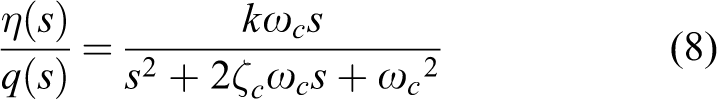
Figure 5 shows the Bode plot of NDF controller at ζc = 0.2 and ζc = 0.6. Moreover, in this analysis, ωc value is taken equal to 7 Hz and ‘k’ is taken as 1. It can be seen from Bode plot that NDF is generally a bandpass filter. If we look deep into the phase angle plot, we can notice that our controller is providing no phase shift with respect to (w.r.t) the input (i.e. vibration signal) at resonant frequency. Similarly, our system equation will also provide no phase shift w.r.t its input, so the combine effect of controller and system will result in no phase shift w.r.t to input signal. This signal is then negatively fed back to the system thus providing the cancelling effect.

Bode plot of NDF controller. (a) ζc = 0.2. (b) ζc = 0.6. NDF: negative derivative feedback.
Similarly, as stated in the previous section, lower ζc value can apply more force on the targeted mode at the same gain value but at the expense of robustness of the controller, while increasing the ζc value will increase the robustness of the controller but will reduce its effectiveness on the targeted mode.
In the previous research, 17 damping ratio of the compensator (ζc ) was taken equal to the damping ratio of the structure (ζ). This requires exact determination of the damping ratio of the structure. However, in this research, ζc is considered as a controlling parameter because the changes in ζc value heavily affect the robustness of the controller. As we know that a flexible system is extremely lightly damped, that is, it has a very low damping ratio (ζ). If ζc is taken equal to ζ, it will increase the performance of the controller (by increasing the controlling force on a particular mode) but will reduce its robustness (w.r.t the natural frequency variation) significantly. Hence, ζc value cannot always be taken equal to ζ value and should be varied according to the performance and robustness required for a particular system.
Experimental set-up
Experimental set-up that is used to verify the two approaches presented in this article is shown in Figure 6 and its schematic is shown in Figure 7. A single link flexible manipulator was constructed using an aluminium beam (575 × 44 × 3 mm3) coupled to a Maxon DC motor (148867 RE 40 150 W, 24 V). The motor is equipped with a gear (203122 GP42C, 66:1) and an encoder (110514 HEDL5540 500cpt, 3ch). Two piezoelectric patches (QP20 W) from Midé were bonded using Eccobond 45 clear epoxy on each side of the beam, one serving as a sensor while the other one as an actuator. Both piezoelectric patches are bonded near the root of the manipulator. Properties of piezoelectric patch are shown in Table 1. An accelerometer is attached at the tip to measure the response of the manipulator. The motor is operated using a voltage supply and a controller. The input voltage to piezoelectric actuator is given through a voltage amplifier (PCB 790A01) having a constant gain of 20.

Experimental set-up of a single link flexible manipulator.

Schematic of experimental set-up.
Properties of piezoelectric sensor and actuator.

The control algorithms that have been presented in this article require prior knowledge of natural frequencies of the system that are needed to be controlled. Therefore, the first step is to determine the natural frequencies of the system. Finite-element method (FEM) simulations and experiments both are performed in this regard. In experimental study, the beam is excited by an exciter which is attached 30 mm away from the fixed end. An accelerometer is used as a sensor to obtain the response of the beam which is attached near the tip. This experimental study is performed to verify the FEM results. The results are compared in Table 2, which shows quite good verification.
Comparison of natural frequencies.

Experimental results
Linear segment with parabolic blends and minimum time trajectories have been used for the trajectory generation. According to trajectory, manipulator rotates 60° in 1.628 s (36.850°/s), and this movement is fast enough to provide substantial vibration at the tip of the manipulator. Detailed experiments have been performed to test the effectiveness of the presented methods on a single link flexible manipulator system. Performances of both controllers have been compared using time. Moreover, robustness study of controllers has also been performed. Following subsections provide details of the various experimental results.
Uncontrolled time and frequency response of manipulator
Figure 8(a) shows the uncontrolled time response plots of the manipulator obtained from an accelerometer attached to the manipulator’s tip. Settling time has also been shown; here, 0.005 V amplitude has been chosen for settling time calculation and this amplitude is so small that it can be considered as the instance where the response has almost died out. One can see from settling time value that the tip oscillation is taking too much time (20 s) to diminish. This time should be reduced in order to increase the productivity and accuracy of the system and to eliminate any possible damage to the structure. Power spectrum of response is shown in Figure 8(b); one can deduce from the result that in our application, only the first mode is contributing to the vibration of the beam which is the case with most of the applications. So if we are able to control the first mode, we can control the vibration of the manipulator. However, in some other applications, more than one mode can contribute to the vibration of the beam; in that case instead of using only one compensator, one has to use parallel compensators where each compensator is designed according to each targeted mode. Hence, each compensator will target the individual mode and their combine effect will provide the vibration reduction of the system.

Response at manipulator’s tip. (a) Uncontrolled time response. (b) Uncontrolled frequency response.
Controlled time response
For real-time control, PPF and NDF controllers were implemented digitally using DAQ board. In case of NDF controller, which requires velocity signal, finite difference method has been used to obtain velocity signal from discrete-time position signal (piezoelectric sensor output). For simplicity, compensator gain ‘k’ is taken as 1, while the plant gain ‘g’ is varied. Moreover, in all experiments, frequency of the compensator is taken equal to the frequency of the system to be controlled and tuned value of gain (g) is used for each case. Controller’s gains are modified in real time in order to get the best possible closed-loop performance. The best choice for gain value is determined by observing the best auto power spectrum response of manipulator’s tip while manually varying the controller gain at different ζc values. Table 3 shows different ‘g’ values used in the experiments for different ζc values. One can notice from the result that as ζc value is increased, ‘g’ value is also increased. This can be explained from controller’s Bode plot as shown in ‘Resonant control technique’ section, that is, at higher ζc values, the magnitude of output from the controller is less than the output at lower ζc values; hence, at higher ζc values, ‘g’ can be further increased in order to raise the voltage input to an optimum level. Figure 9 shows the controlled time responses for PPF and NDF controllers at different controller damping ratios (ζc ), respectively. Time ‘0’ corresponds to the time when the motor has stopped running. One can easily notice from the results that settling time decreases as the compensator damping ratio ‘ζc ’ is decreased. The effect of ζc value on controller’s performance will be further discussed in robustness study. Finally, settling time results show that NDF controller has performed better at all ζc values as compared to PPF controller.
Tuned gain values at different ζc .

PPF: positive position feedback; NDF: negative derivative feedback.

Time response of controllers. (a) ζc = 0.2. (b) ζc = 0.5. (c) ζc = 0.8.
In many automated industries, robotic arms are working continuously and repeatedly; in this regard, the controller should be able to provide constant performance during repetitive manoeuvrings. To check this, we conducted seven experimental trials at each ‘ζc ’ value under same conditions. We further calculated the average settling time and standard deviation of all the experimental trials which have been shown in Table 4. One can easily conclude from Table 3 that settling time readings at each ‘ζc ’ value are almost constant and there is not much deviation in the results. Hence, it is shown that the controllers are able to give constant performance during different experimental trials and overall NDF is a better choice than PPF.
Average settling time and standard deviation at different ζc.

PPF: positive position feedback; NDF: negative derivative feedback.
Robustness study of each control law
In this section, we will evaluate the performance of the controllers when there is a difference between the natural frequency of the system and the controller centre frequency. This study is useful in situations where the natural frequency of the system is difficult to obtain or have large errors in it. In ‘PPF control’ and ‘NDF control’ sections, it was concluded from Bode plot analysis that robustness of controllers depends on the ‘ζc ’ value, the higher the ‘ζc ’ value the better is the robustness of the controllers and vice versa. In order to experimentally validate this concept, two experiments were conducted using 0.8 and 0.2 as ‘ζc ’ value. These experiments were performed to study the effect of compensator damping ratio on compensator’s robustness when the difference between the natural frequency of the system and the controller centre frequency is increased. The discrepancies in natural frequency estimation were visualized by changing the compensator centre frequency from 0.75*w to 4*w in regular steps and then obtaining the time response of the manipulator at each centre frequency; here, ‘w’ represents the original natural frequency of the system. A total of six experiment trials were performed at each compensator centre frequency, and these trails were further used to obtain the vibration attenuation in terms of auto-power spectrum of manipulator. Figure 10(a) and (b) shows the vibration attenuation using different controller centre frequency at ζc = 0.2 and ζc = 0.8, respectively. In general, it can be observed from the graphs that when the difference between the original natural frequency of the system and the controller centre frequency is increased, the magnitude of vibration attenuation degrades significantly. This degradation of performance is quite severe at ζc = 0.2, where there is large drop in vibration attenuation as we move away from ‘w’. While at ζc = 0.8, the drop in vibration attenuation is not that extreme and our controller is still able to provide 35 dB of vibration attenuation even if there is +300% (if controller centre frequency = 4w) error in natural frequency estimation.

Vibration attenuation as compared to the uncontrolled case at different compensator frequencies. (a) ζc = 0.2. (b) ζc = 0.8.
As explained in ‘Resonant control technique’ section regarding robustness of the controllers, the same can be deduced from the experimental analysis presented in this section, that is, the robustness of the controllers can be increased by increasing the ζc value. Furthermore, through these experiments, the effect of ζc values on controller’s performance has been highlighted; hence, it is shown that the optimal value of ζc depends on whether the natural frequency of the system is known accurately or not and how much it is expected to change. If the system natural frequency is known accurately, lower ζc value is a better choice.
Conclusion
In this article, vibration suppression performances of two resonant control techniques namely PPF and NDF have been compared. For this purpose, these techniques were applied experimentally on a single link flexible manipulator featuring piezoelectric actuator and were further analysed in terms of settling time and robustness at different controllers damping ratios. After thorough study of time domain results and robustness, it has been concluded that NDF controller is overall more effective in suppressing vibration than PPF controller based on particular system developed in this study. Author believes that these control techniques can be further applied to control structural vibration in flexible space robots, multi degree of freedom manipulators, lightweight wind turbine blades and other structures where only few modes are contributing to the vibration of the system. The future work will be focused on applying these control techniques to multi degree of freedom system.
Footnotes
Declaration of conflicting interests
The author(s) declared no potential conflicts of interest with respect to the research, authorship, and/or publication of this article.
Funding
The author(s) received no financial support for the research, authorship, and/or publication of this article.