
Abstract
This article proposes a trajectory generator for quadcopter to intercept moving ground vehicle. For this air–ground interaction problem, we formulate the trajectory generation problem as quadratic dynamic programming in a moving-horizon scheme based on the quadcopter kinematics and observation to ground vehicle. The closed-form solution of quadratic dynamic programming in each iteration enables this algorithm a real-time replanning performance. Thereafter, segmented trajectory rule, inspired from commercial flight landing regular, is implemented to guarantee smoothness in approaching and interception to moving ground target from comparably far origin. Our established algorithm is verified through both simulations and experiments.
Introduction
Nowadays, micro-aerial vehicle (MAV) is becoming a hot research topic. In military missions, MAV would be widely used in scouting, communication, and transportation in the near future. In civilian aspect, some E-commerce companies have made attempts using MAV to finish “the last mile” delivery to customer. MAV with multi-copter structure has special advantage compared with traditional unmanned aerial vehicle, leading to an easy implementation in indoor environment. Also, the development in micro-electro-mechanical system and smart sensor extends the range of MAV applications. Improvement in computation power makes it possible to execute complex tasks such as real-time searching and tracking on moving target.
In an air-to-ground interaction task, computer vision system and trajectory generation algorithm are equally important, but facing different aspects. The major concerning of vision system in the tracking problem is the reliability in a complex dynamic background. Vision-based tracking and landing is proposed in the study by Wenzel et al. 1 with a basic PID controller.[Please provide expansions for “PID, PD, and GPS.”] On the other hand, air–ground interaction requires a fast and accurate aggressive approaching maneuver based on trajectory generation and control. However, major part of such interaction is finished by height-keeping tracking flight followed by vertical landing 2 or simply track a moving target without interception. 3,4
Aggressive maneuver and trajectory generation of a quadrotor have been widely investigated. General Tau theory is introduced in quadrotor perching movement 5 and four-dimensional trajectory planning. 6 Minimum snap metric (e.g. two-norm of the fourth derivative of position) is proposed in the studies by Mellinger and Kumar 7 and Richter et al., 8 which generates an aggressive trajectory within a tight constraint. Being motivated by Mellinger and Kumar, 7 an avian-inspired approach is proposed in the study by Thomas et al. 9 for quadrotor grasping. In the literature above, polynomial curves are used to approximate a trajectory, where coefficients are then determined by numerical optimization with respect to a given cost functional. To the best of our knowledge, the minimum snap method is not yet been used in dynamic scenario which needs a real-time replanning capability.
The main contribution of this article is twofold: (1) the dynamic programming (DP) trajectory generation approach for a moving ground target interception and (2) the segmented trajectory rule (STR). Trajectory on DP does not require an explicit dynamic model when generating the trajectory. All steps are calculated analytically to reduce the computational burden. STR is an empirical scheme rather than a single algorithm, which performs well in the experiments. To the best of our knowledge, this kind of scheme is new to the air–ground interception problem of MAV.
Compared to the tracking-landing scheme of a quadcopter toward a moving ground target, which focuses mainly on the error-feedback control, this hierarchical structure avoids the stabilization and convergence problems in the single control problem. Also, a smooth trajectory is much easier for quadcopter to follow, especially when the starting point is comparably far from the target. The major difference between minimum snap approach and this DP approach is that the former generates a one-time optimal trajectory through multiple predefined waypoints, while our proposed DP approach generates trajectory iteratively with the new target states given in an updated way. Therefore, the DP approach in this article is capable of real-time replanning in a dynamic environment. Also, the polynomial trajectory with the minimum snap metric requires high-quality modeling of a quadcotper, because the control sequence is directly depending on the motors speed. While our approach is independent of the controller, which is more suitable for practical implementation.
We organize the rest of this article as follows. The section “Problem formulation” briefly formulates this problem as trajectory intersection of quadcopter and ground vehicle. The section “Dynamic programming” gives the derivation of quadratic DP. The section “Multi-level implementation of DP on quadcopter” gives a detailed description of trajectory implementation on quadrotor and STR. The sections “Simulation ” and “Experiments ” introduce simulation and experiment results, respectively. We close the article by drawing a conclusion and discussing some potential research topics in the section “Conclusion.”
Problem formulation
To acquire a trajectory approaching and intercepting mobile ground vehicle, the algorithm requires replanning capability. The trajectory tracking controller also needs to keep up with the planner. The trajectory can be a sequence of frames (attitude, velocity, or waypoint). Acceleration control (attitude mode) 7,8 is the fastest-responding approach, since the rotation speed of propeller is directly ordered. But this type of trajectory planning requires high-quality modeling of the physical system. Position control 10 has independent path planning and tracking part but needs the tracking controller responding fast. Otherwise the reaction to target position update will be very slow. Velocity mode 11 provides smart respondence to dynamic target, while an outer-loop controller guarantees the position convergence.
Quadrotor dynamics and control
As a typical structure of MAV, quadrotor has great advantages in mechanical simplicity and application extension. Four propellers distributing around the quadrotor provide thrust to quadrotor flight. The orientation of total thrust is always vertical to the quadrotor body. This property is important for deducing the Euler angle set point, after the trajectory is generated as accelerations at three axial directions in the section “Multi-level implementation of DP on quadcopter.”
To describe the kinematics and dynamics of a quadrotor, two right-handed coordinates, earth frame E and body frame B, are set. The earth frame is fixed on the ground, considered as an inertial frame. And the body frame is fixed on the quadrotor. Twelve variables in total are used to describe the full states (Figure 1):
position on the ground frame (px, py, pz);
Euler angle roll, pitch, and yaw (φ, θ, ψ);
velocity refers to the earth frame (vx, vy, vz); and
angular rate toward body axis (ωx, ωy, ωz).

Dynamics of quadrotor is highly nonlinear. Except basic body dynamics, motor, propeller, and battery also have complicated relations.
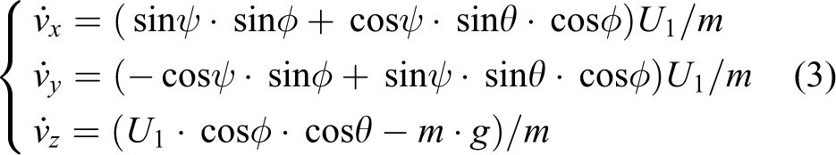
By neglecting the nonlinear relationship between the lift force and the rotation speed, we derive the following simplified translation equations

and the dynamics of Euler angles

where ωx, ωy, and ωz are angular velocities.
Define control variable U1 as the total thrust, the acceleration on earth frame can be defined as
For the derivative of angular rate, three parts are taken into consideration: the torque generated by propeller’s lift, the angular momentum of body, and gyroscopic effect of propellers. Combine all three parts together, and then the differential equations to the angular velocity are as follows
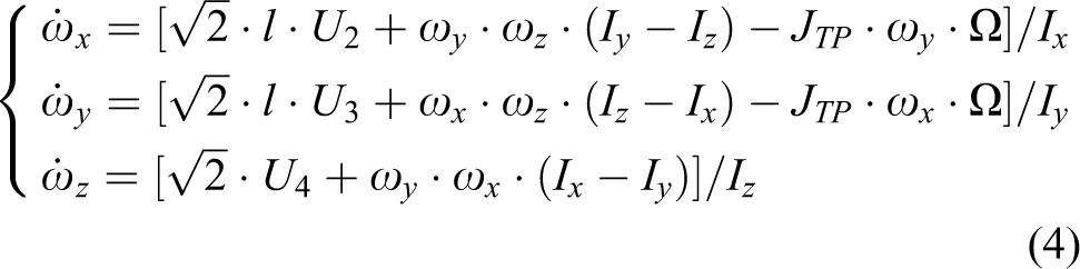
In the set of equations above, U1, U2, U3, and U4 are the controller outputs of four feedback loops for z, φ, θ, and ψ. They are manipulated by the rotation rate of four propellers. The control outputs are decoupled to rotation speed of each motor ωi using the equations below in real experiments. This is a typical roll–pitch–height controller used in the section “Fixed-point one-step approaching”

where k represent the coefficients of PID controllers.
For all the control output, single-loop PID is used for four states, z, φ, θ, and ψ. Conventionally, a simple PD controller is good enough to keep a quadrotor hovering. But in purpose of eliminating the steady-state error in height control, integral part is added to the controller. There are different kinds of flight controllers which have been proposed and widely used.
Ground vehicle interception
Assumption 1
The basic motion behaviors of ground vehicle are straight-line motion and turning. The motion is along with random small changes in direction. The time and degree turn is prior unknown.
We use a kinematic model to describe the motion of each ground target as equations (6) and (7).


where the linear motion velocity, heading angle, and angular velocity are denoted as v0, θ, and ω. The random noise and constant unknown disturbance are denoted as ν and η, respectively. Thus, the trajectory of ground vehicle during a period of time with steep turning is

where t0 is the initial time, ta is the initial turning time, tt is the turning duration, and tf is the terminal time.
To stop the ground vehicle, the trajectory of quadcopter and ground vehicle should intersect at the end

where tf is the final time.
Assumption 2
Because turning time and degree are unpredictable, we allow the quadcopter hold the approaching process on the air if the ground vehicle begins a turning. The quadcopter starts planning until the ground vehicle starting another straight-line motion.
Dynamic programming
Basic quadratic DP
DP 13 is a method to break an optimization problem into easy-to-solve subproblems. Consider a general form of time-varying discrete system

and the objective function

where
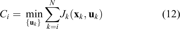
where Ci is a minimal value of J. This derivation leads to the Hamilton–Jacobi–Bellman (HJB) equation, which is generally a nonlinear partial differential equation. The HJB equation is usually solved backward in time. We derive Bellman equation and show the backward recursion of the cost-to-go value function

To make this problem easy to solve, we describe Ji as a general quadratic form
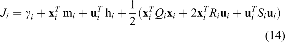
where

According to the studies by Starr et al. and Palunko et al., 13,14 the backward recursion of the coefficients in Ci are as follows

The optimal control sequence to minimize J can be obtained by solving the first-order optimality condition


Online quadratic DP
A one-step optimal trajectory is not adequate in the dynamic scenario which both target vehicles and (possible suddenly appeared) obstacles keep moving. The requirement of the DP method here is to provide trajectory with real-time replanning capability. Concept of receding horizon optimization is introduced as a combination of DP, called quadratic DP. Denote j as the jth recursion. When the target is moving, the target state
Denote N as the planning step length and M < N as the applied step length during which the quadrotor really tracks this trajectory (e.g. N = 400, M = 100 in Figure 2). After M steps, the quadrotor generates a new trajectory segment aiming at new target position


Comparison between one-step DP and QDP. Blue box is the window of each recursion in x-axis. DP: dynamic programming; QDP: quadratic dynamic programming.
Figure 2 shows the comparison between one-step DP (dash line) and quadratic DP (solid line) toward a fixed-point target. One-step DP generates an S-shape trajectory with clear acceleration and deceleration process with small overshoot, while quadratic DP shows a similar tendency but be slower to arrive the set point.
Multi-level implementation of DP on quadcopter
Trajectory to attitude control sequence
To reduce the computational burden of DP, we use the kinematic model instead of dynamic model. The kinematic model is a double integrator, which takes only translation of the quadrotor into consideration as a mass dot

where
We also define the objective function (14) as a minimization problem

where
As
Considering the Z–Y–X Euler angle, the rotation matrix from earth frame to the body frame is derived as follows 15
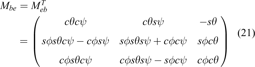
where s and c represents sine and cosine functions, respectively.
Not losing the generality, we lock ψ = 0 in equation (18), and add gravity coefficient

and control set point

We can put su, sφ, and sθ as the set point command sequences for a quadrotor in the attitude mode to follow.
Position feedback
For a quadrotor navigating in the environment, though acceleration control signal is more straightforward, the difference between the PID output and the set point may lead to a position drift. For a nonlinear system, it could be linearized as

where

and then position feedback is introduced by a simple feedback gain K as

The above equations give a general scheme of feedback control on position drift in tracking the trajectory. The trajectory tracking control is not discussed in detail since there are various methods on this topic. In our implementation, we use a cascade control scheme on the horizontal plain, with PD for inner loop and PID for outer loop, and a single-loop PID controller on height/throttle.
For the controller’s design, the parameters are handcrafted. This exactly goes specific to the aerial platform itself. However, we use the parameter set which performs better in attitude stabilization, hovering, and fixed waypoint flight, no special treatment to this DP trajectory is implemented.
Segmented trajectory rule
To handle the complexity of the approaching and interception process (e.g. sudden turning, obstacles, and distant origin), we are inspired by the regular commonly used in air traffic control. 16 Airfield traffic pattern is a typically rectangular standard path that commercial flights commonly follow before landing for flight safety. We use a similar scheme called STR, which divides the whole process into three segments (commonly using term “leg” in air traffic control): cruising, tracking, and final approaching.
The cruising segment is a long and high-speed path aiming at the target. Since the maximum speed of the quadrotor platform in our experiment is 10 times larger than the ground vehicle, the movement of target vehicle during this time is small. Therefore, the path is approximately linear as in Figure 3. The target state

Segmented trajectory pattern: cruising, tracking, and approaching.
In the tracking segment, the quadrotor follows the target vehicle with the same velocity and heading direction. During this period, quadrotor recovers from the aggressive attitude and large absolute velocity in the cruising segment, catches up with the target, and prepares for the final approaching. The velocity of sideslip should be reduced before starting to approach.
Unlike both the cruising and the tracking segment, the approaching segment is more likely to be a problem of prediction. The target in the approaching segment is a “fixed” interception point. But this fixed point is also updated by the current vehicle state
Simulation
In this section, we use MATLAB simulation to verify the effectiveness of our method. Our simulation system has two major packages: trajectory generator to give a command sequence as algorithm 1 and dynamic model of quadrotor as in section “Problem formulation” to track the trajectory. The dynamic model part is implemented with the solver ode45. The physical parameters in the dynamic model are identified from a real quadrotor platform accordingly.
As a real-world implementation for air–ground interception, shepherd mission in the International Aerial Robotics Competition (IARC) Mission-7 is a challenging task which have in its fourth year. The ground vehicle’s behavior in simulations and experiments are modeled the same as IARC Mission-7 rule 17 for testing. The statement goes specific to competition for the purpose of demonstrating a real implementation performance on a real hardware platform. The behavior of the ground robot also imitates a typical ground target (straight line, turning with noise, sudden stop, and U-turn). We use no prior knowledge of ground vehicle motion rule (velocity, turning time, disturbance, etc.) for trajectory generation in simulations and experiments.
Fixed-point one-step approaching
First simulation aims to verify the basic performance when the target is fixed. In this simulation, DP is implemented for only one-step, while position feedback as in section “Position feedback” is only implemented on height, which makes this quadrotor in the roll–pitch–height mode. In the simulation, the initial state of quadrotor is set as
Figure 4(a) shows the trajectory in the earth frame. The dashed line is the trajectory generated by DP, while the solid line is the position of quadrotor tracking of the trajectory. The quadrotor gets close to the target through a relatively smooth curve within a short period of time (300 steps, 3 s). There is a lag between the planned path and the real one, due to the coarse single-loop PID/PD controller. This kind of controller can hardly catch up a rapid change of the set point.

Simulation results of fixed-point target approaching. (a) Position trajectory. (b) Direct command sequence.
Figure 4(b) shows value of throttle, roll, and pitch. There is a difference at the beginning because the set point can be nonzero initially, while states have to begin from zero initial value and transfer through a two-stage dynamic process. This difference coincides with the tracking delay in xy position in Figure 4(a).
However, the simple roll–pitch–height controller is verified to be not qualified in a more complex scenario, due to the accumulation of lag error. x–y–z controller (waypoint mode) is implemented in all the following simulations and experiments.
Moving target tracking
In IARC shepherd problem, the moving ground targets are iRobot Create. The goal of quadrotor approaching in this problem is to intercepting and triggering the sensor of the ground vehicle. Figure 5 is a close look of ground vehicle trajectory used in the coming simulation.

A detailed description of the ground vehicle’s behavior in simulation.
Without any external interference, the ground vehicle remains to move along a noisy straight line within a time period Tl, then keeps rotating (resulting U-turn) in Tu. We denote

Comprehensive simulation results. Simulation video link is listed in the section “Conclusion.” (a) Ts = 2: 3D plot. (b) Ts = 2: colormap of acceleration. (c) Ts = 2: xyz-plot. (d) Ts = 14: 3D plot. (e) Ts = 14: colormap of acceleration. (f) Ts = 14: xyz-plot.
Parameter description.
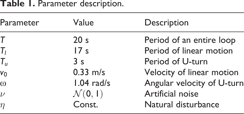
Figure 6(a) to (c) shows the case
Figure 6(d) to (f) shows the case
Obstacle avoidance
In a flight operation, the priority of obstacle avoidance is always higher than navigation and guidance. The algorithm may override the controller for avoidance when the obstacle is detected unexpectedly. Our algorithm should be able to recover to interception after the obstacle is passing by. Especially in the high-speed cruising segment, the reaction time is very short since the range of laser scanner is limited. We do not discuss advanced obstacle avoidance path planning here. In the basic control level, an obstacle avoidance command always overrides all planning levels and implements the most direct command to get far away from the moving obstacle. Therefore, we implement basic maneuver-like “hard aport” or “change lane” when detecting obstacle and recovery to cruising after passing by.
Figure 7(a) to (f) shows two similar cases with the interference of obstacles. Quadrotor detects the obstacle and begins to evade by implementing a “hard-aport” maneuver. The PID controller tracks the trajectory with a significant delay. After passing by the obstacle, there is a dense recovery acceleration as shown in Figure 7(b) and (e).
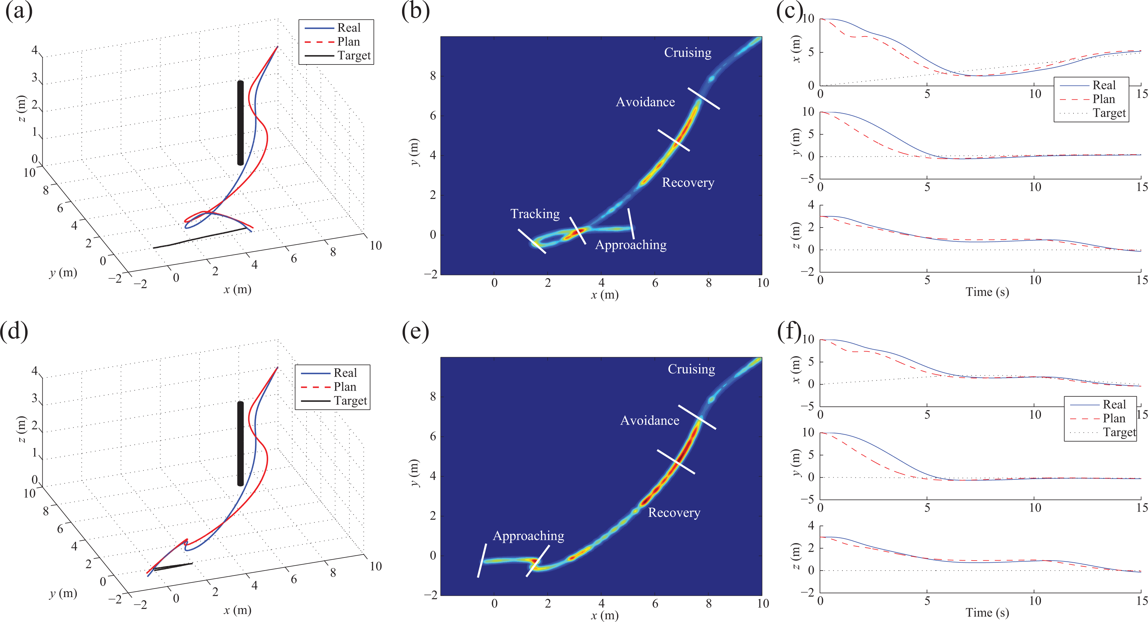
Comprehensive simulation results. Simulation video link is listed in the section “Conclusion.” (a) Ts = 2 with obstacle: 3D plot. (b) Ts = 2 with obstacle: colormap of acceleration. (c) Ts = 2 with obstacle: xyz-plot. (d) Ts = 14 with obstacle: 3D plot. (e) Ts = 14 with obstacle: colormap of acceleration. (f) Ts = 14 with obstacle: xyz-plot.
Figure 7 shows the quadrotor can intercept a ground vehicle with the interference of obstacle. However, this kind of obstacle avoidance maneuver is really coarse and cannot guarantee every success. Empirically, obstacle avoidance is mainly concerned in a higher level path planning with a proficient knowledge for optimal path.
Experiments
Experiments in this article are all conducted in the ZMART IARC Testbed as shown in Figure 8(a), which is a MAV task test environment majorly for the IARC shepherd problem. This system can also test other functions such as obstacle avoidance, exploring, mapping, and formation. OptiTrack vision capture system provides an accurate position and attitude data at a rate of 120 Hz with an accuracy of millimeter. The test quadrotor is equipped with minimum system hardware consists of inertial measurement unit, flight controller, Zigbee communication module, a frame size of 330 mm, and electric propulsion system.
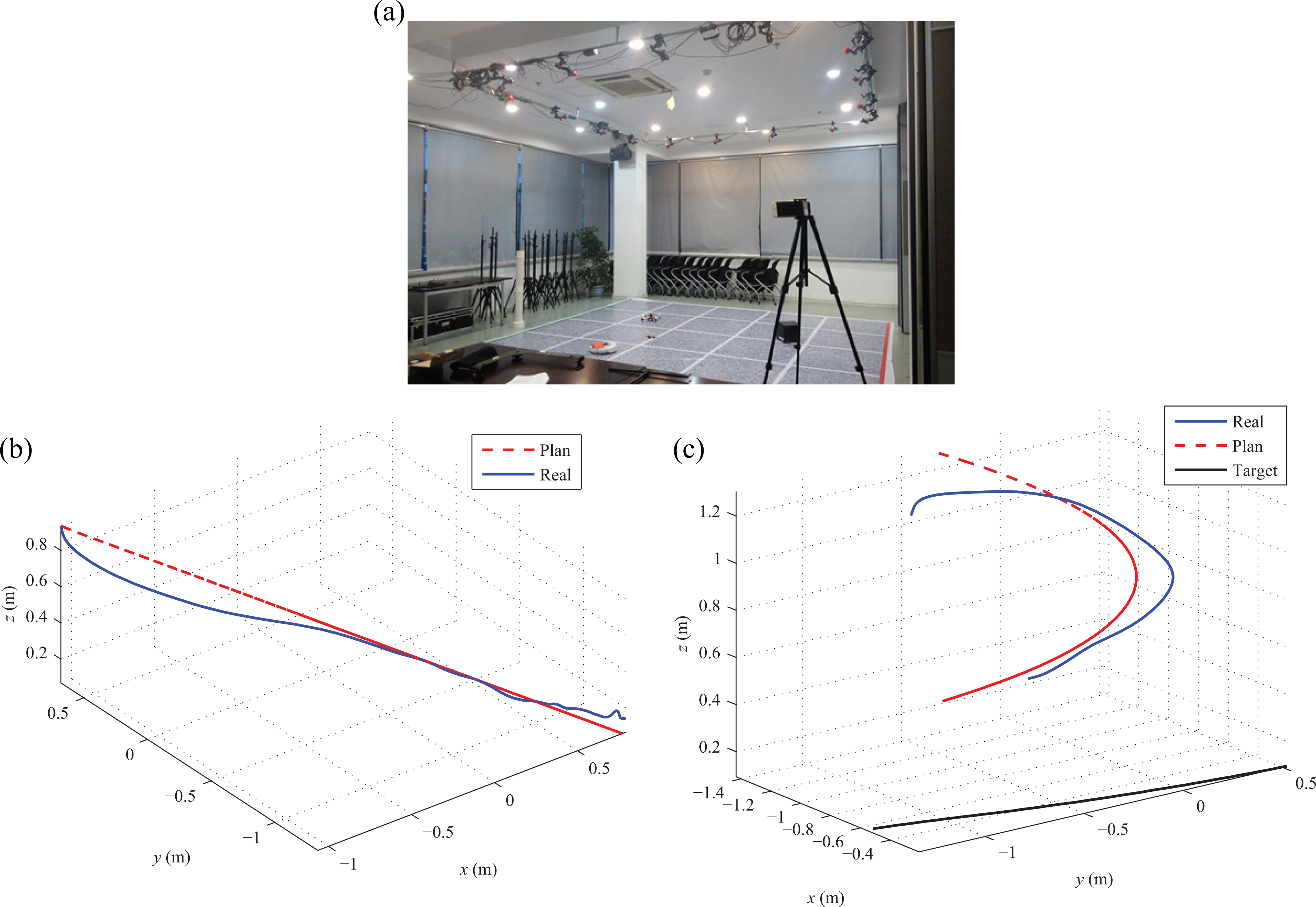
Comprehensive experiment results. Experiments video link is listed in the section “Conclusion.” (a) ZMART IARC testbed. (b) Fixed point approaching. (c) Moving target approaching.
In this experiment, the quadrotor and the target are marked by infrared reflectors. The motion capture camera is sensitive to infrared ray. The flight controller unit is DJI NAZA, a widely used commercial flight controller, working in the attitude control mode. An outer loop position controller is running on the ground station computer. The communication between quadrotor and ground station is through Zigbee.
Basic functional test
In the basic test as Figure 8(b) and (c), basic functional segments, fixed point, and moving target are tested independently.
Figure 8(b) shows the quadrotor approaches the target rapidly with a smooth trajectory, which is for final approach segment. Compared to the simple single-loop PID controller in simulation, the DJI NAZA flight controller performs better in trajectory tracking. Because DP does not provide strong constraint on final time Tf, this experiment also needs to measure the approaching time Tr, which is a basic parameter to predict the interception point in approaching function.
In Figure 8(c), an iRobot Create, coded exactly the same as (6,7) and Table 1, carries reflective balls and moves on the ground as a target. The result shows that the quadrotor can catch up and track the target steadily.
Competition scenario test
To test the performance of this method comprehensively, we use all elements in the testbed to imitate the real competition scenario. The black box available in Figure 9(f) is to trigger the sudden turning. Ground vehicle starts a U-turn when hitting this box. The white bar in Figure 9(i) is an obstacle. This test scenario is proficient but simple for basic probable condition with unpredicted target turning and suddenly appeared obstacle.

Comprehensive experiment results. Experiments video link is listed in the section “Conclusion.” (a) Common condition: 3D plot. (b) Common condition: xyz-axis. (c) Common condition: experiment snapshot. (d) Double-turn condition: 3D plot. (e) Double-turn condition: xyz-axis. (f) Double-turn condition: experiment snapshot. (g) Obstacle avoidance: 3D plot. (h) Obstacle avoidance: xyz-axis. (i) Obstacle avoidance: experiment snapshot.
Figure 9(a) to (c) is a common entire process without any interference. It shows a similar pattern as the simulation in Figure 6(a) to (c), thus verifies the accuracy of the simulation system in the section “Simulation.” In the z-axis of Figure 9(b), (e), and (h), there is a constant gap between set point and system output because the NAZA flight controller has a dead zone in height. The dead zone leaves huge effect in the final approaching segment, for inaccuracy in height control may lead to wrong interception point. Therefore, we use a mixture of direct throttle command and height controller to solve this problem.
With the existence of a black box in Figure 9(f), it becomes more complex since the ground vehicle may turn twice during the process, one for head collision and another for 20 s count. Turning behaviors are well addressed by tracking segment, since the quadrotor can keep tracking until the ground vehicle finishes turning. Tracking segment is the most steady segment among three. No matter how complex the target behavior is, the quadrotor can track and prepare for the final approaching.
Figure 9(g) to (i) shows the experiment with an obstacle. This obstacle is located by reflective balls. The quadrotor successfully evades then recovers to track the target. For the equipment limit, the effective area of this testbed is less than 4 m × 4 m. We cannot implement some experiments in longer time or larger distance because the quadrotor and ground vehicle will easily get out of the bound. Those experiments above have verified the basic functional effectiveness.
Conclusion
In this article, we propose a simultaneous tracking and approaching method for quadrotor toward mobile ground vehicle. Trajectory generation method based on DP is used. STR is implemented to divide the whole process into three parts to guarantee smooth and robust control sequence till the final interception under different conditions. The quadrotor achieves aggressive approaching toward moving ground targets with smooth trajectory in both simulations and experiments. Simulation and experiment video is in link (http://v.youku.com/v_show/id_XMTU0NzM5ODE2MA==.html?from=y1.7-1.2).
The future work could be as the following two aspects: (1) terminal time constrain should be taken into concern as a strong constrain in trajectory generation and (2) the quadrotor should be able to locate itself and target with onboard payloads, vision for example, instead of external supports. Furthermore, this approach will be improved to a learning-based structure, such that it can be trained to touch ground vehicles, without human adjustment for algorithm parameters.
Footnotes
Acknowledgements
The author acknowledge support from the National Natural Science Foundation of China and the Science Fund for Creative Research Groups.
Declaration of conflicting interests
The author(s) declared no potential conflicts of interest with respect to the research, authorship, and/or publication of this article.
Funding
The author(s) disclosed receipt of the following financial support for the research, authorship and/or publication of this article: This work was supported by the National Natural Science Foundation of China (grant no. 61473253) and the Science Fund for Creative Research Groups (grant no. 61621002).