
Abstract
This article presents a unified design for lightweight robotic arms based on a unified description of structure and drive trains. In the unified design, the drive trains and structural dimensions are parameterized as design variables, and a major objective minimizes the total mass of robotic arms satisfying the constraint conditions and design criteria. To implement the optimization problem, a mapping relationship between mass and torque of drive trains is introduced as their power–density curves, which enable a unified description of structure and drive trains combining with the dynamics of robotic arms. In this implementation of unified design, there are two modules: structure optimization and drive trains design. The finite element method with nonlinear programming by quadratic Lagrange algorithm is adopted to implement the structure optimization. Moreover, the dynamic analysis in MSC ADAMS is achieved to design the drive trains of robotic arms. This method could uniformly evaluate all components of robotic arms in mass and continuously search the global optimal results. Finally, a design example on this unified design is compared with a referenced design to illustrate the validity and advantage of the proposed scheme.
Introduction
Robotic arms have been widely used in industrial production, agriculture, service and space explorations, and so on. However, most of these existing robotic arms have obvious disadvantages: low payload–weight ratio, bulky structure, high power consumption, and low safety in human–robot coexistence environment. 1 As a result, lightweight design on robotic arms is required to meet the requirements in high performance and special tasks such as space manipulation. 2 To address the above problems, many researchers have launched on the design of lightweight robotic arms, which is a complex system including drive trains design, structure design, dynamic control, and so on. 3
Drive trains account for large proportion of whole weight of robotic arms, so the lightweight design on drive trains integrating motors and gears is very promising. To improve the power–density of motors for robotic joints, Seo and Rhyu proposed a design of axial flux permanent magnet brushless DC (BLDC) motors. 4 Jing et al. studied the structure optimization of BLDC motors by finite element method (FEM) to increase its power–density. 5 However, these investigations on the power–density of motors are not enough. Chedmail and Gautier proposed a method on the optimum selection of drive trains to minimize the total mass of robotic arm with given trajectories. 6 Pettersson and Ölvander presented a multiobjective optimization on the drive trains of an industrial robotic arm. 7 Zhou et al. 8 presented an optimization problem on drive train of lightweight robotic arm to select its motors and gearboxes from a commercial catalog. Moreover, Park et al. reported a new modular drive train for a dual arm robot manipulator to make the robotic arm lighter and safer in human–robot coexistence environment. 9 However, these researches mainly focused on the drive trains design, disregarding the influence on the structure from the renewal of drive trains.
There are some reported optimization designs on structure to obtain the optimal dimensions of robotic arms. Albers and Ottnad used a topology optimization to optimize the structural dimensions of links for lightweight robotic arms based on FEM. 10 Zhang et al. introduced an integrated modular design approach by FEM and dynamic simulation to design a lightweight, high stiffness, and compact robotic arm. 11 Shiakolas et al. proposed a structural optimization of robotic arms with task specifications, 12 in which the length and cross-sectional parameters were optimized to minimize the required joint torque by dynamic analysis. In addition, Schrock et al. designed a wheelchair-mounted robotic arm in carbon fiber and polycarbonate to achieve lightweight design and enhance the structural stiffness. 13 However, these researches mainly focused on the structural optimization to improve the dynamic performance without considering its influence on drive trains.
Structure and drive trains are interactional and expected to consider together. An integrated approach, which simultaneously implemented the structural and drive trains optimization, was recently proposed to design a lightweight anthropomorphic arm. 14 However, this structural optimization only considered the dimensions of links while disregarded the parameters of joint shell; in addition, the index number of motors and gears were defined as the design variables of drive trains optimization, so these nonassociated and discrete design variables resulted in a large amount of computations and locally optimal results. Therefore, a complete description on structure and effective optimization design is required to design globally optimal lightweight robotic arms.
In this article, the whole structure consisting of links and joint shell is optimized, and drive trains including motors and gears are designed. These design variables of structure and drive trains are generous and interactional, so their characteristics and laws are studied and a unified design based on the inherent laws of structure and drive trains is expected to design lightweight robotic arms.
This unified design consists of two modules: structure optimization and drive trains design. The FEM with nonlinear programming by quadratic Lagrange (NLPQL) algorithm 15 is utilized to optimize structural dimensions of links by means of minimizing its mass and satisfying the constraints. Besides the structural dimensions of links, the dimensions of joint shell are also considered. These dimensions of joint shell are dependent on the type of selected drive trains, which are in turn dependent on the whole structure of robotic arms. Therefore, the unified design is a complex optimization problem, and an inherent law of structure and drive trains is required to clear up their relationship and solve this problem. Above all, the objective minimizes the total mass of robotic arms in this study, so the mass of drive trains is one of the principal variables in the inherent laws. In addition, the torque of drive trains is also key variables as it is a bridge linking the parameters and mass of structure. As a result, a mathematic formulation between the mass and torque of drive trains is proposed as the basic theory of the inherent law, which enables all components of robotic arms to evaluate uniformly in mass. The mathematic formulation is defined as power–density, which is developing with technique because it is related to the materials, topology structure, and speed of drive trains. This study achieves a fitting curve as joint’s power–density based on candidate motors and gears reflecting current technique. The fitting power–density and dynamics of robotic arms formulate the unified description of drive trains and structure. The unified design performs static structural analysis in ANSYS Workbench and dynamic analysis in MSC ADAMS (MSC. Software, 2013 Version). Finally, an example on the unified design is compared with a referenced design 14 to demonstrate its effectiveness and advantages of the proposed scheme.
A design scheme of lightweight robotic arms
In this section, a design scheme and some considerations are introduced as an optimization problem of lightweight robotic arms. In the optimization problem, design variables on links and joints are defined, and a major objective minimizes the total mass of the robotic arm satisfying the corresponding constraint conditions and design criteria.
Scheme model and considerations
Figure 1 shows a scheme model of lightweight robotic arms with five degree of freedom (DOF), which includes 2-DOF shoulder, 2-DOF elbow, 1-DOF wrist, and a hand gripper. This study focuses on the lightweight design of robotic arms, so that mass distribution of robotic arms is supposed to be as close as possible to the driving joint. For example, the joint 4 is arranged at location closing joint 3 to reduce the excited vibration.

Scheme model of lightweight robotic arms.
In addition, the aluminum alloy is chosen as the material of structure to meet the requirements of lightweight robotic arms. Meanwhile, in order to achieve better dynamic performance and more compact structure, BLDC motors with higher power density and harmonic drive gearboxes (HGs) with higher reduction ratios are utilized to form drive trains. In this work, the HGs are used as transmission components for all other joints except for joint 4 due to only a slender space in link 2, so a slender planetary gearhead (PG) is utilized in joint 4 to increase the torque. Moreover, an electric gripper with servo drive acts as the end effector to pick up target.
This lightweight design is a study on general method and not for specific tasks, so kinematics analysis is not the necessary work in this research. However, the motions of robotic arms are one of conditions in dynamic analysis; therefore, a pick-and-place operation (PPO) in joint space is specified as the trajectories to calculate the required torques of robotic arms, and the dynamic equation is generally described as

where
For complex robotic arms, it is difficult to formulate an accurate and parameterized mathematic model to optimize them. Hence, the dynamic model of the robotic arm is established by the virtual prototype technology in MSC ADAMS to implement dynamic simulation as accurate as possible.
Design variables
To optimize robotic arms, the design variables including structural dimensions of links and parameters of joints are defined as follows.
Parameterized structural dimensions of links
The structure is one of major components and is optimized as the basis of joint optimization for lightweight robotic arms. As shown in Figure 2, the robotic arm is parameterized in assembly (marked in red) and structural dimensions (marked in black) of links. The assembly dimensions determine the kinematic performance of robotic arms. To obtain a higher kinematics performance of the robotic arm in the overall workspace, the assembly dimension L
2 is set to 0.7 times L
1 referring the maximum values of global conditioning index (GCI).
16
Moreover, to limit the computational work, some assembly dimensions H
1 and L
3; some structural dimensions of links, such as lengths l
1 and l
2; and outer radius R
1 and R
2 are assumed as constants. While the other structural dimensions of links, such as inner radius r
1 and r
2, the major axes a
1 and a
2 of ellipse groove and the minor axes b
1 and b
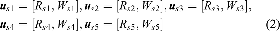
2 are defined as the design variables of links. For the sake of brevity, here the design variables of links are described as a vector

Parameterized structural dimensions of links.
Design variables of joints
Similarly, joints are also major components and account for large proportions of whole mass of a lightweight robotic arm, so their optimization potential is huge. The joint design adopts a modular approach to improve the efficiency of optimization design, and the detailed configurations of modular joint are shown in Figure 3.

Modular joints.
The modular joints consist of drive trains and shells, and the design variables
where the shell dimensions
As shown in Figure 3, the gearboxes as the major components of drive trains directly determine the shell dimensions of joints, considering the fit in assembly process and lightweight objective. The previous study 17 summarized the relationships between shell dimensions and selected drive trains as

where Rhdi and Whdi are the maximum radius and width of HGs from the product catalog. For a candidate drive train, the major dimensions are correlative with its rated torque. However, the rated torque of the drive train is continuous variables and difficult to continuously map shell dimensions during optimization. Therefore, a segmented function about the shell dimensions mapping the rated torque of joints is represented by
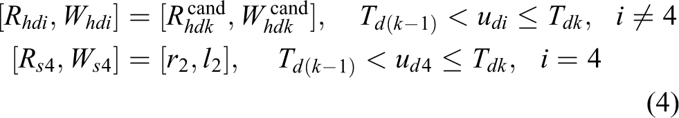
where Tdk
is the rated torque of the kth candidate drive train, and [

As a result, the design variables of the robotic arm can be briefly denoted by a vector
Constraints and design criteria
To implement the optimization design, the constraints on structural strength and design criteria of drive trains are introduced in this section.
Constraints on structural strength
Since the renewal of structural dimensions and design variables of joints will inevitably lead to the changes of structural strength, some constraints on structural strength of the robotic arm making it safety should be formulated as

where σm denotes the maximum Von-Mises equivalent stress of the robotic arm and σy is the yield strength of the structural material. dm is the maximum total deformation of the robotic arm, and dmp is the maximum permissible deformation. S 1 is a structural safety coefficient, and these constraints are evaluated through the static structural analysis in ANSYS Workbench.
Design criteria of drive trains
The drive trains consist of motors and gears, and a schematic model of drive train with load is depicted in Figure 4. The required toque τgi of the ith joint of robotic arm can be obtained through the dynamic calculation, and the corresponding required torque of motor τmi can be transformed as
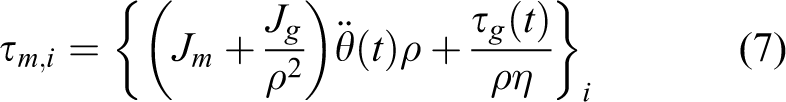
where Jm represents the inertia of motor rotor, and Jg denotes the inertia of gear rotor. ρ represents the gear ratio, and η is its transmission efficiency.

Model of drive train and load.
To ensure the drive trains with enough ability to drive payload under given trajectories, the following design criteria of drive trains are expressed as

where
The driving ability of drive trains derives from the motors, so their driving ability is also checked as

where
These above design criteria ensure the driving capability of motors and gears, but the lightweight demands limit their capacity. To obtain suitable candidate drive trains satisfying driving capability and lightweight, the combining design criteria of motors and gears are described as

Objective function
In this study, the objective of optimization problem minimizes the total mass of the robotic arm satisfying constraint conditions and design criteria, and the objective function is formulated as

where f
1(

These design variables are expected to meet aforementioned constraint conditions and design criteria, which are equations (5), (6), (8), and (9). In addition, the design variables of links need meet the specific range as

where

Implementation of the unified design
The design variables are generous and the optimization problem is complex, so the optimization design is divided into two modules: structure optimization and drive trains design. The former is performed by means of computer software with NLPQL algorithm, while the latter is implemented by dynamic analysis in MSC ADAMS. Meanwhile, the design variables of the structure and drive trains are interactional; therefore, a unified description makes two modules interact and achieve the optimal result in the whole design.
Structure optimization
Nowadays, finite element analysis, such as ANSYS, is widely used in structural analysis and optimization design of products. In this study, a digital model is built to optimize the structural dimensions of links in ANSYS Workbench, where an NLPQL algorithm is integrated to obtain the optimal results. The NLPQL algorithm 15 is an effective method to solve nonlinear optimization problems. In structure optimization, considering the joint parameters as constants, the objective function is expressed as

where
Basic theory of the unified description
After achieving the structure optimization, the dynamic analysis is able to get the required torques of joints, which is obtained by assuming the joint parameters as constants in dynamic model. However, the calculated torques will result in new joint parameters, such as joint mass, which are expected to renew their values in dynamic model. To realize the renewal, a mapping relationship between the rated torque and mass of drive trains is required and defined as power–density curve. As shown in Figure 5, the torque is a bridge of structural dynamics and power–density curve of drive trains, which enable the structure and drive trains to evaluate uniformly in mass. Therefore, the mapping laws of power–density curve of drive trains are the basic theory of unified description and introduced as follows.

Unified description of structure and drive trains.
Roos has been presented the mathematic formulations of rated torque Trated m and mass mm of the homogenous motors, 18 which are described as


where Cm is constant for a specific motor type with same coiling condition. l m and rm are the radius and length of the rotor, respectively. ρm is the average mass density of motor. These parameters are associated with the topological structure and coiling method of the motor.
By substituting equation (16) into equation (17), a mapping relationship between the rated torque Trated m and mass mm of the ith motor can be described as

This mapping law implies that the rated torque of a motor is positively correlated with its mass when the parameters ρm and Cm are constant.
In addition, gears are also one of major components of drive trains and applied to increase torque. If a gear is working at rated speed, its transmission efficiency and gear ratio are assumed as constant. Based on the above hypothesis, when the motor is operating at rated torque, the output torque of the ith drive train disregarding the inertia of output axis can be expressed as

where T 0 is output torque of the drive train, and η and ρ are transmission efficiency and gear ratio, respectively. For homogenous gears working at approximate rated speed, the transmission efficiency might be same. Considering the influence of the inertia from the motor and gear, the rated output torque of a drive train reflecting its driving capacity can be modified as

Meanwhile, the mass md of the drive train consisting of the motor’s mass mm and the gear mass mg can be expressed as

Then, a mapping relationship between the mass and rated torque of drive trains can be formulated by means of equations (18) and (19). Moreover, the mapping relationship of drive trains represents their power–density curve, which is related to the type of the drive trains. For a certain type of drive trains, the mapping relationship can be generally marked as

where Fj is a mapping function related to the jth type drive trains, which is classified according to their topological structure, rated speed, and materials. Based on the power–density curve, the unified description is built and the unified design is performed.
The routine of the unified design
As a result, the unified design is executed to minimize the total mass of robotic arms based on the unified description of the structure and drive trains. Figure 6 depicts the routine of the unified design, which consists of the structure optimization of links and drive trains design.

Routine of the unified design.
Firstly, the initial parameters
When finishing structure optimization, the optimal design variables
Design example
In this section, the unified design and a referenced design approach 14 are implemented to compare the optimization on a 5-DOF lightweight robotic arm, and their results are compared to verify the validity of the unified design.
Referenced design approach
The referenced design integrated the structure optimization and the optimum selection of drive trains from catalog for a lightweight robotic arm, so it is complex approach and needs a large number of computations to choose the optimal drive trains. To understand the referenced design easily, an optimization problem14 is presented as follows

where the design variables
In the referenced design approach, the calculation process of the optimization problem is presented as follows.
As shown in Figure 7, before implementing the optimization problem, we need to specify several feasible design points (

where xDV
represents the results of rounding up the design variables x = [

The flow chart of the referenced design.
In the complex algorithm, the design point minimizing objective function value is defined as the best point
Input trajectory and parameters of the robotic arm
In the example, the target payload is defined as 2 kg, which acts on the end effector as a mass point. The assembly dimensions determining the kinematic properties of the robotic arm are accordingly given as H 1 = 230 mm, L 1 = 380 mm, L 2 = 270 mm, and L 3 = 108 mm, which can meet the requirement of specific workspace of the lightweight robotic arm. 16
The trajectories as the input conditions of dynamic simulation are required to specify. This example will maneuver a PPO,
17
and the PPO in joint space starts from an initial position
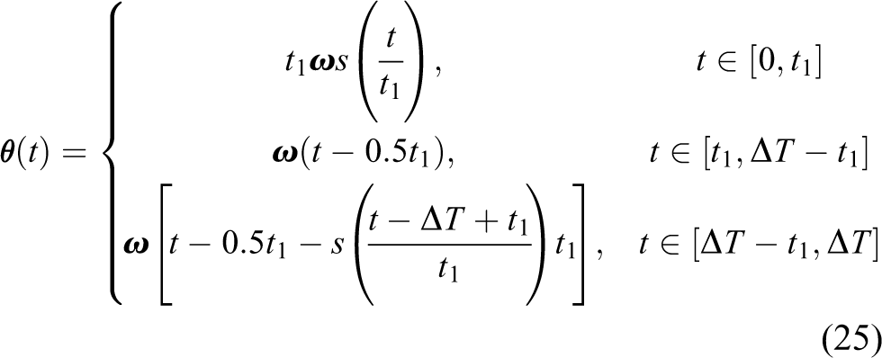
where s(t) = t
6 − 3t
5 + 2.5t
4,
In this example, the structure material is chosen as aluminum alloy (6061-T6) and its yield strength is σy = 270 MPa. Meanwhile, to evaluate the constraints on structural strength and rigidness, the structural safety coefficient is set to S 1 = 2, the maximum permissible deformation is defined as dmp = 1 mm, and the minimum condition εN is 0.000001. In addition, both the error conditions e and εC are set to 0.0001, and the choice safety coefficient is set to S 2 = 1.3.
Besides the structural parameters, the candidate motors and gears are required to optimize the joints of lightweight robotic arms. In this example, the EC series of BLDC motors
19
from the MAXON Motor Corporation, Switzerland, are applied to design joint motors. In addition, the fourth joint adopts a GP series PG from the MAXON Motor Corporation due to its location in a slender space, whereas other joints take the HGs with HFUC-2UH Series Units
20
as transmission elements. The related technical data of the candidate harmonic gearboxes, PGs, and motors are described as column chart in Figure 8(a) to (c), respectively. Each candidate motor or gear provides four parameters including mass (mm
or mg
), rated torque (
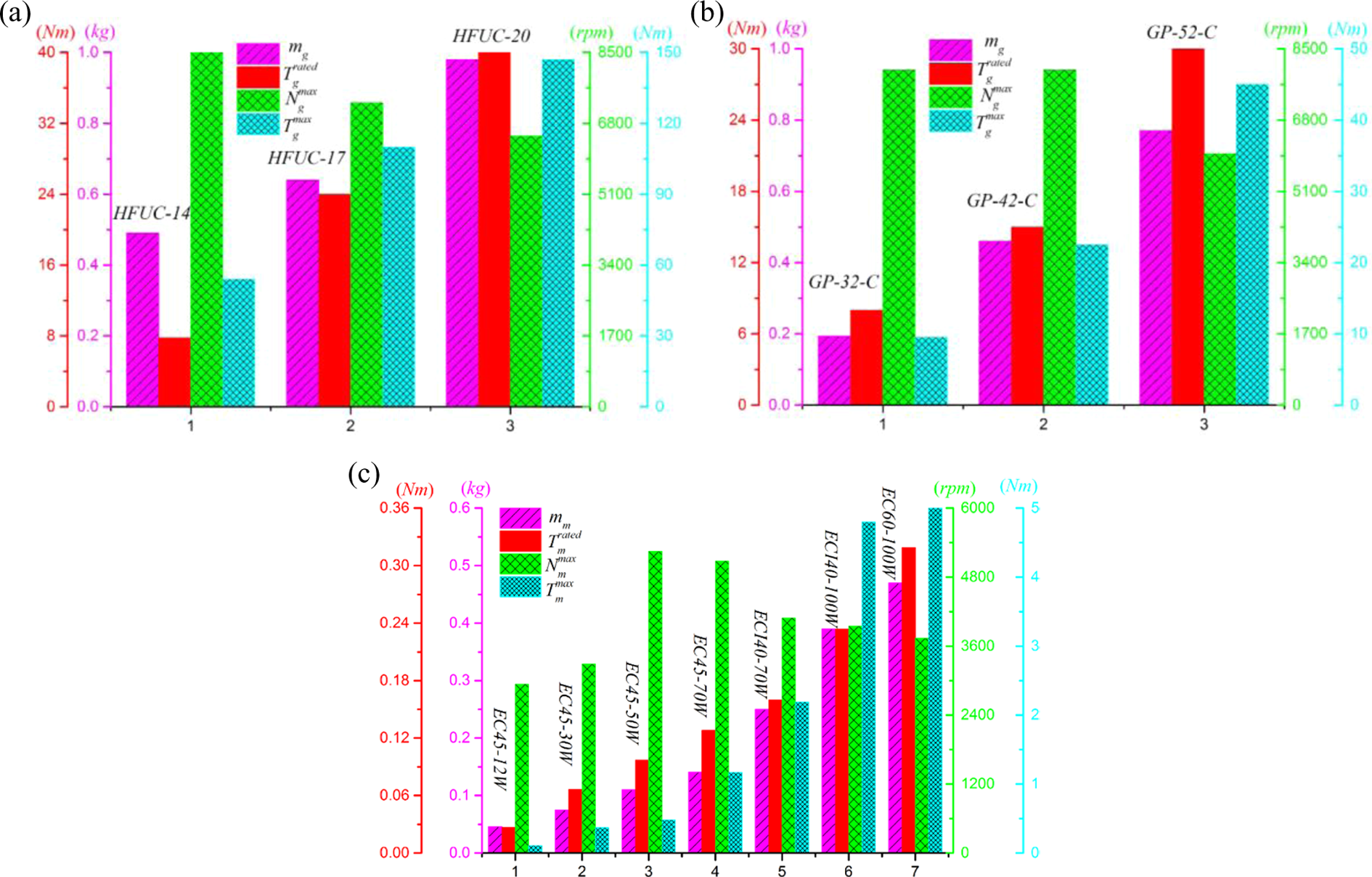
Based on the descriptions of the product catalog, the gear efficiency is dependent on its operation speed. In this work, all candidate motors have near-identical rated speeds ranging about 3000–5000 rmin−1, under the action of gears with reduce ratios ig = 113 for PG and ig = 100 for HG, so the combination of motors and gears makes the robotic joints work at an expected speed of 30–50 rmin−1. Therefore, the gear efficiency of each candidate gear is set to η = 70%, which is an average value from the product catalog based on the approximate rated speed.
Initialization of design variables and power–density curve
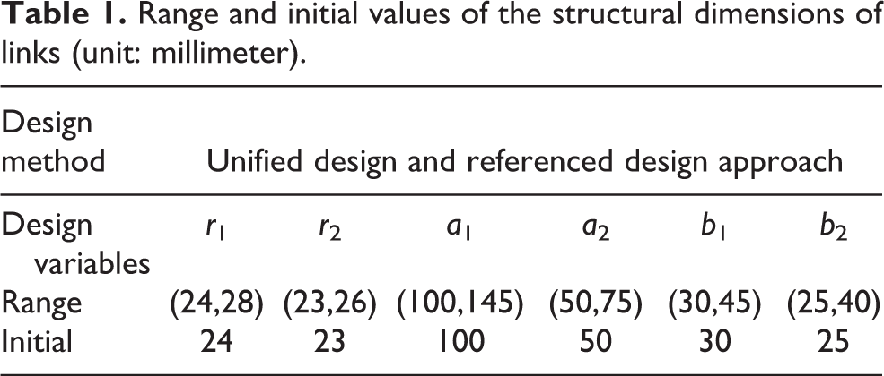
In this design example, the initial values and ranges of design variables of links are required and listed in Table 1.
Range and initial values of the structural dimensions of links (unit: millimeter).
In addition, the power–density curve, which is a mathematic relationship between mass and torque of drive trains, is required to optimize the drive trains. In theory, this relationship exists and depends on rated speed, structure, and materials of drive trains. Furthermore, the power-density formula is developing and variable with technical progress. Therefore, this study adopts a fitting curve based on a series of candidate drive trains reflecting the current technology. In this case, we need to combine motors and gears as candidate drive trains according to the combination criteria mentioned in equation (10). These drive trains used to fit a curve should possess same structure, materials, and rated speed (actually approximate due to the limitation of the number of samples). In this study, two kinds of gears are adapted, so there are two types of drive trains. The first-type drive trains (A1–A7) composed of the motors and HG are listed in Table 2. Similarly, the second-type drive trains (B1–B7) composed of the motors and PG are listed in Table 3.
The first type candidate drive trains.
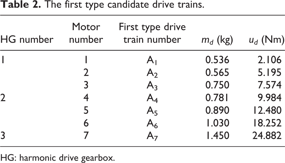
HG: harmonic drive gearbox.
The second type candidate drive trains.

As shown in Tables 2 and 3, the mass md and rated torque ud of drive trains are computed by means of equations (20) and (21), respectively. As a result, the mapping relationship between the mass and torque of drive trains is obtained by curve fitting. As shown in Figure 9, the first type power–density curve md = F 1(ud ) is obtained based on the first type candidate drive trains listed in Table 2, while the second type power–density curve md = F 2(ud ) is achieved using the second type candidate drive trains, as shown in Table 3. Both the power–density curves will be utilized to optimize the drive trains of lightweight arms in the unified design.
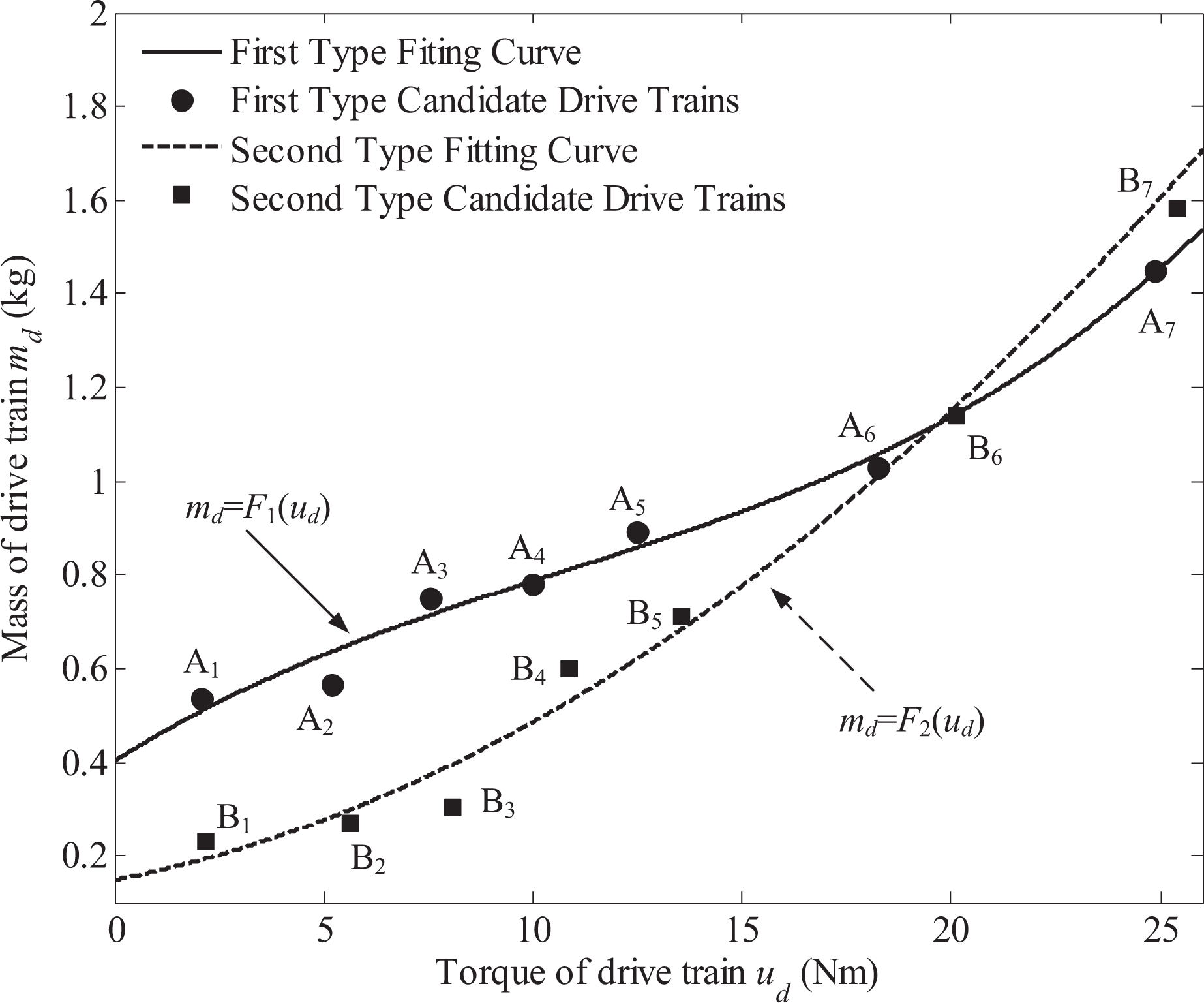
Mapping relationship between the mass and torque of drive trains.
In the optimization, the initial components of drive trains are roughly estimated using statics when the robotic arm with initial structural parameters spreads to limit position. In the unified design, the design variables of drive trains are rated output torque ud
, whereas their design variables in referenced design are the index number of motors (
The initial components and values of design variables of drive trains.

Results and discussions
Based on the same input conditions, constraints, and initial parameters, both design approaches on a lightweight robotic arm are achieved to compare their results. The referenced design approach takes 346 iterative calculations to obtain the optimal lightweight robotic arm, while the unified design only spends 46 iterative calculations to get a lighter structure.
Figure 10 illustrates the convergences of partial design variables of links based on the referenced design approach and unified design, respectively. Table 5 lists the optimal results of all design variables of links based on both designs and a group of trade-off results, respectively. Compared to the results of referenced design, the optimal values of unified design are larger; this result implies the optimal slots and inner space of links is shortly larger in the unified design. The trade-off result is one in-between case and introduced later. In addition, the convergences of design variables of links based on the unified design are uniformly forward to the optimal results, while their convergences based on the referenced design are fluctuating toward the objective values due to the discrete design variables and rounding treatment in computation of drive trains, which affect the parameters of links.

Convergences of the partial design variables of links. (a) r 1 and r 2 based on the referenced design approach. (b) r 1 and r 2 based on the unified design.
The optimal results of design variables of links (unit: millimeter).

Figure 11 depicts the convergence of partial design variables of motors and gearboxes based on the referenced design. Similar to the case in Figure 10(a), the convergences in Figure 11 are fluctuating and finally stable in the optimal values. This fluctuating convergences result from limiting the design variables of motors and gears as discrete integrals and rounding these decimals in calculation. These limitations of discrete variables and round function (24) leads to the disorder and rough computations, so that the referenced design needs a large number of computations to obtain the final results, which are not global optimal solutions.

The convergence of partial design variables of motors and gears based on the referenced design. (a) Motor 1 and gearbox 1. (b) Motor 3 and gearbox 3.
Based on the unified design, Figure 12(a) depicts two fitting power–density curves and the optimal results of drive trains, and Figure 12(b) shows the convergences of design variables of drive trains along its power–density curves of the joints 1–4 at the 21th, 31th, 39th, and 46th iterations, respectively. The power–density curves express the inherent law of candidate drive trains integrating the motors and gears, so that the optimal results can be continuously searched and quickly convergent along the law curves. Only four iterations are used to obtain the optimal results of drive trains, and other iterations (46−4 = 42) are executed in structural optimization. Compared to the root joints, the end joints are more quickly convergent, for example, the four iterations of joint 4 are almost overlapping together due to small effect from structure and other joints. Especially, joint 5 is completely unaffected from structure and other joints, so it is convergent at one point around A1 as shown in Figure 12(a), which does not need to be locally enlarged in Figure 12(b).

Convergence of drive trains along power–density curves based on the unified design. (a) Power–density curves and optimal results of drive trains. (b) Convergence of design variables of drive trains for joint 1–4.
To compare the optimal results of all joints based on two designs, the optimal components (in red) and values of design variables of drive trains based on the unified design and referenced design are listed in Table 6. In the referenced design, the design variables of joints are the index number of motors and gears, and convergent to a series of integrals, which are basis to check the components according to Tables 2 and 3. In the unified design, the design variables of joints are output rated torque and convergent to some exact values, such as 12.83 ∊ (A5, A6), which represents the optimal value locating between A5 and A6 on curve.
The optimal components and values of design variables of drive trains.

The exact results can be referred to design the drive trains of a lightweight robotic arm, but the integrating design on motors and gears is a challenging work. In the practice, actuators of joints adopt the available motors and gears selected from product catalog to integrate drive trains, which discretely distribute on the fitting curve. These candidate drive trains approaching and exceeding these exact values are chosen as the optimal components to ensure them with certain redundant capacity adapting much wider range tasks. For example, the optimal result is 12.83 Nm locating between A5 and A6, so that the candidate A6 is the optimal component of joint 1. In this case, the optimal components used in both optimized lightweight robotic arms are completely same, although the design variables based on the unified design are continuous and fine values while counterparts based on the referenced design are discrete values.
Figure 13(a) depicts the convergences of both the best and worst design points based on the complex algorithm in the referenced design. Figure 13(b) shows the convergence of the whole mass of robotic arm by means of the unified design and trade-off design. Comparing the convergence rates of the objective function for the two design methods, we can summarize that the unified design can significantly reduce the number of iterative calculation. Moreover, the optimized mass of the robotic arm based on the unified design is 7.62 kg, while the optimized mass based on the referenced design approach is 8.15 kg. The results illustrate that the unified design has better feasibility and efficiency to achieve a more lightweight design for robotic arms. The trade-off design can obtain one in-between mass, which is 7.982 kg.
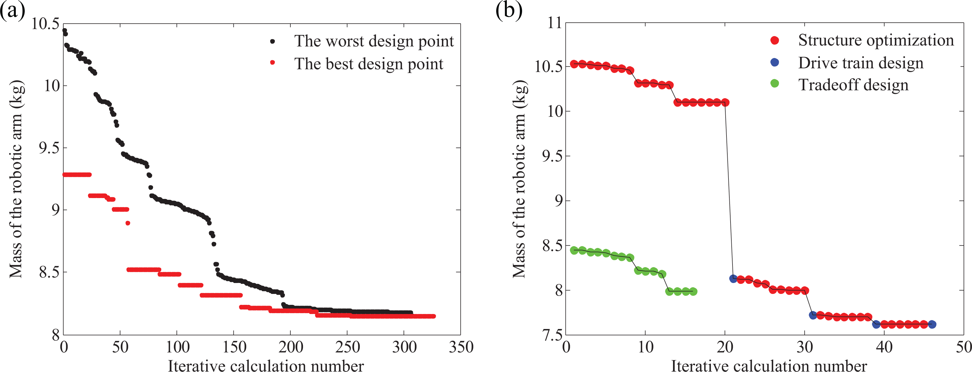
Convergence of mass of the robotic arm. (a) f(
The red points in Figure 13(b) represent the mass trend of the robotic arm only considering structure optimization, while the blue points imply the mass changing trend in the drive train design. These data reflect the interaction between the structure and drive trains, so the unified design based on the unified description of structure and drive train is important. Considering the feedback of optimized drive trains, the structure is optimized again until the difference between f(
The more lightweight robotic arm is obtained in unified design when the optimal values of drive trains are considered. If we weigh to select the optimal components (red symbol in Table 6) as drive trains of robotic arm after quick unified design, the optimal dimensions of links related to these optimal components will yield the trade-off results listed in Table 5. Moreover, the convergence (green points) of the total mass of robotic arm results from trade-off design (
Conclusions
A lightweight robotic arm was designed by utilizing the proposed optimization method, in which the design variables describing links and drive trains, constraints on structural strength and design criteria of drive trains, as well as the objective function were formulated and developed. The joint shell dimensions are determined by drive trains due to depending on them, and a unified quantitative description on both the structural dimensions of links and drive trains was considered to reduce the computation complexity. The results show that the proposal method can achieve an optimal design with minimum mass and high efficiency while satisfying the constraints and work conditions and design criteria of drive trains.
A unified design based on unified description of structure and drive trains was introduced to optimize the lightweight robotic arm. In this unified design, the motors and gears were combined as a whole component based on the design criteria of drive trains, and then a mathematic relationship between the mass and torque of drive trains was presented as its power–density curve, which is bonds of the unified description on structure and drive trains.
Finally, the unified design method was compared with a referenced design approach to deal with the same optimization problem on lightweight robotic arms, and the results show that the unified design is validity. Considering the mathematic law between the mass and torque of drive trains in the design process, the unified design provided a high efficiency and fast computation optimization for the lightweight robotic arm. In addition, the design variables in the unified design were continuous renewal and convergent to fine values and result in a lighter objective mass of robotic arm.
In this work, the mathematic law between the mass and torque of drive trains was obtained by fitting curve method based on the available motors and gears. The further application and theoretical study on the mathematic law remains an open problem for future research.
Footnotes
Declaration of conflicting interests
The author(s) declared no potential conflicts of interest with respect to the research, authorship, and/or publication of this article.
Funding
The author(s) disclosed receipt of the following financial support for the research, authorship and/or publication of this article: This study was supported by National Natural Science Foundation of China (Grant No. 51575409) and partially by the Fundamental Research Funds for the Central Universities (20411009).