
Abstract
The goal of this article is to present a number synthesis method for the self-adapting upper-limb rehabilitation exoskeletons. The human joint kinematics and the variability of joint axes around their supposed locations were analyzed; the axes misalignments caused by the wearing error and the movement coupling between joint rotations and axes motions in human joints were taken into account, and the kinematic incompatibility of upper-limb exoskeletons was investigated from an over-actuation perspective. Then, a number synthesis method of the self-adapting upper-limb exoskeletons was proposed by using the traditional degrees of freedom analysis approach of spatial multiloop chains. Applying this method, the basic chains of the self-adapting four-degrees of freedom shoulder–elbow and five-degrees of freedom shoulder–elbow–forearm exoskeletons were synthesized and classified into three and two groups, respectively. Finally, the feasible simplified chains of the self-adapting upper-limb exoskeletons were investigated with the consideration of the quasi-anthropopathic feature and structure simplicity, and several examples were enumerated. The proposed simplified chains could be used as the candidates for further studies on the performance analysis, the chain compare and selection, and structure design of the self-adapting upper-limb exoskeletons.
Introduction
Physical rehabilitation training is an essential treatment for patients with upper-limb disabilities caused by stroke or traumatic brain injuries. In process of rehabilitation training, patients can strengthen their weakened muscles, regain their limited joint range of motions, and thus restore their motor functions gradually. Manual-assisted training has been the conventional technique widely used for upper-limb rehabilitation therapy. With this technique, upper limb movements are manually executed by therapists. To improve a patient’s motor functions, a long, repetitive, and intensive training process should be carried out. 1,2 Nevertheless, manual-assisted training has some limitations, including fatigue among therapists during a long and labor-intensive training, in which case the training sessions are often shortened. Additionally, a quantitative evaluation of the therapeutic outcome is not possible. 3 A solution to deal with the aforementioned limitations is the exoskeleton-assisted training, in which therapists are responsible for the nonphysical interaction and supervision of patients while an exoskeleton carries out the intensive and repetitive manual tasks. Exoskeleton-assisted training features several advantages over the manual-assisted training, including low labor intensiveness, long duration, easy repeatability, and task orientation. 4 –6 However, problems in exoskeleton-assisted training emerge as a result of the close physical interaction between exoskeletons and human upper limb. Specially, the issue of axes misalignments between human and exoskeleton joints must be well dealt with when the exoskeletons are connected to human upper limbs. Otherwise, axes misalignments lead to undesired interactional loads (UI loads) in human–robot chains. 7 –9 These unwanted loads change as the human–robot chains move, and the training becomes uncomfortable or even unsafe when they are large enough.
An effective approach to coping with the axes misalignments is the self-aligning design of the exoskeletons, in which supererogatory passive joints are introduced into the exoskeleton structures (usually simple kinematic models of human limbs), these introduced DOFs ensure the exoskeletons to be kinematically compatible with human limbs and hence avoid the UI loads. According to the installed positions of the added joints in exoskeletons, the self-aligning exoskeletons can be classified into two categories: the self-tracing exoskeletons in which the axes of exoskeleton’s active joints can trace the axes of human joints during the training and the self-adapting exoskeletons which are able to remove the UI loads without the necessity of the tracing of human joint axes. In the self-tracing exoskeletons, additional joints are commonly introduced into the exoskeleton kinematic chains between the base and active joints or between two subsequent active joints. These added DOFs allow the axes of exoskeleton’s active joints to trace the axes of human joints during the training. 10 –13 As an example, four passive DOFs were added into the NEUROExos elbow exoskeleton to ensure the axes alignments between the exoskeleton and human elbow joints. 13 In the self-adapting exoskeletons, additional joints are introduced into exoskeletons to remove the UI loads without the necessity of the exoskeleton’s active joint axes to trace human joint axes. 7,14 –20 The idea of self-adapting was first used in the study by Schiele and Van Der Helm 7 for the kinematic design of a nine-DOF upper-limb exoskeleton, where two passive joints were adopted to connect human and exoskeleton forearms. Following this strategy, a shoulder exoskeleton named the ShouldeRo was designed in the studies by Dehez and Sapin and Galinski et al. 15,16 The ShouldeRo exoskeleton features two active DOFs and four passive DOFs, with the kinematic chain formed by the passive joints serving as the human–robot connective subchain. In the study by Olivier et al., 17 a self-adapting exoskeleton was designed for hip flexion/extension (F/E) assistance, in order to escape the UI loads, five passive DOFs were used in the exoskeleton. By mounting the exoskeleton’s active joints on the passive moveable mechanisms, a joint motion decoupling-based method for the design of self-adapting exoskeletons was presented in the study by Stienen et al. 18 In the study by Sergi et al., 19 a graph-based method for the number synthesis of self-adapting lower-limb exoskeletons was presented; however, it is only applied to planar lower-limb exoskeletons. A systemic study for the number synthesis of self-adapting upper-limb exoskeletons was proposed recently by Jarrasse and Morel. 20 In this work, how to introduce passive DOFs into exoskeletons to eliminate the UI loads caused by wearing errors was shown clearly, and a method based on the rank analyses of the twist and wrench spaces of human–robot chains was presented. While this method is general, the location variability of human joint axes and the movement coupling between joint rotation and axes motion were ignored, and dealing with such factors in the number synthesis of exoskeletons was not clarified.
In this article, the joint kinematics of human upper limb is analyzed, the generalized kinematic models of human joints are proposed, and the kinematic incompatibility caused by the axes misalignments is investigated on the basis of the over-actuation analysis of the human–robot chains. Then, a number synthesis method of the self-adapting upper-limb exoskeletons for training application is proposed by means of the traditional DOF theory of spatial multiloop chains, in which the axes misalignments caused by the wearing error and the motion coupling of human joint rotations and axes movements are considered. Finally, the basic and simplified chains of the self-adapting exoskeletons with four and five DOFs are synthesized, and the discussions on number synthesis method and future works are presented.
Joint kinematics and human–robot kinematic incompatibility
Joint kinematic models of the human upper limb
According to anthropotomy, human upper limb (here the wrist and hand are not considered) is composed of five major bones (scapula, clavicle, humerus, radius, and ulna) and their connective joints; its kinematics is mainly determined by the shoulder, elbow, and forearm complexes. 21 As shown in Figure 1, the shoulder complex involves the clavicle, scapula, humerus, and four connective joints, namely, the sternoclavicular (SC), acromioclavicular (AC), glenohumeral (GH), and scapulothoracic (ST) joints. In kinematic studies, the shoulder complex is usually regarded to be composed of an inner and outer portion. 22 The outer portion corresponds to the GH joint with three revolute DOFs, that is, the adduction/abduction (AD/AB), F/E, and internal/external (I/E) rotations of the humerus. The GH joint is kinematically equivalent to a three-DOF spherical joint and is commonly adopted as a simplified kinematic model of the whole shoulder complex when the motion of the shoulder girdle is neglected. The inner portion corresponds to the shoulder girdle and can be modeled as an appropriate closed kinematic chain, with which the composite kinematics of the SC, AC, and ST joints is described. According to the literatures, 23 –26 the motion of the shoulder girdle is primarily a consequence of the human humeral pointing action. When the humerus is held in a fixed pointing direction and a humeral I/E rotation is given, little to no additional movement is observed within the human shoulder girdle. These studies revealed that the motion of the shoulder girdle is coupled with the AD/AB and F/E rotations of the humerus, and hence, the center of the GH joint moves along with the rotation of the humerus through a certain coupling motion. Therefore, the human shoulder complex can be regarded as a generalized three-DOF GH joint with a floating center (e.g. a 3-DOF spherical joint with a floating center but with the center position being coupled with the rotation of the spherical joint).

Shoulder complex.
The anatomical structure of human elbow complex (Figure 2) is mainly composed of the humerus, ulna, radius, and the ulnohumeral (UH), radiohumeral (RH), as well as proximal radioulnar (PRU) joints. The major function of human elbow complex is the F/E rotation, which is mainly realized by the UH joint. However, this rotation cannot be simply described by a pure hinge joint with a fixed axis because both the position and the orientation of the F/E revolute axis change during the rotation of human elbow complex. 27,28 Such kinematic feature has been studied by Stokdijk et al. and Brownhill et al., 29,30 in which the motion of F/E revolute axis was investigated with the screw displacement axis (SDA) method; specifically, a set of SDAs were determined through the direct tracking of the ulna relative to the humerus, with each single SDA representing a small incremental change in the F/E angle. These works show that the behavior of the UH joint is similar to that of a “loose hinge joint” instead of that of a pure hinge joint. Moreover, the F/E axis over the rotation range of human elbow complex is not firm but changes along with the angular positions of the UH joint and around an average SDA location. According to the kinematic aspects described above, the UH joint can be considered as a generalized one-DOF revolute joint with variable axis, and the joint angular configuration and the F/E axis’s location have a certain corresponding relationship during the rotation of elbow complex.

Elbow complex.
As shown in Figure 3, the forearm complex is composed of the ulna, radius, and the PRU and distal radioulnar (DRU) joints. The major function of the forearm complex is to realize the pronation/supination (P/S) rotation and thereby rotate the hand palm from palm up to palm down or vice versa. Given that such function is fulfilled by the composite motion of the ulna, radius, and joints comprising the human forearm, the P/S kinematics cannot be described by any single bone motion. In the studies by Tay et al. 31,32 the in vivo kinematics of human forearm was studied on the basis of the computed tomography (CT) technique and the SDA analysis method. In these studies, the CT images of four static forearm positions, namely, the maximum pronation, maximum supination, 60° pronation, and 60° supination, of six subjects were obtained and analyzed. The results show that the P/S revolute axis extended from the radial head between its kinematic center and the PRU joint to the dorsal portion of the ulnar head at the DRU joint. Moreover, the location of the P/S axis was variable at different forearm angular positions. In the study by Matsuki et al., 33 the in vivo kinematics of a normal human forearm was studied with the 3D–2D registration method, and dynamic CT scans were taken during the P/S motion from maximum supination to maximum pronation, with the elbows flexed to approximately 45°. In this work, the P/S axis passed through the center of the radial head and ulnar head at the 1.9 ± 0.7 mm posterior from its geometric centroid. During the forearm rotation, the location of the P/S axis was not fixed because of the dorsal translation of the ulna. Despite the differences in existing studies, their findings indicate that the forearm complex can be regarded as a generalized one-DOF revolute joint with an instantaneous axis and that a one palm up or palm down configuration corresponds to a certain location of the P/S revolute axis.

Forearm complex.
Human–robot kinematic incompatibility
When an exoskeleton is connected to the human upper limb, a human–robot chain is formed. During rehabilitation training, the upper limb is moved by the exoskeleton. For comfort and safety, UI loads caused by the kinematic incompatibility must be removed. However, doing so is difficult and we should understand the ways in which the UI loads are induced.
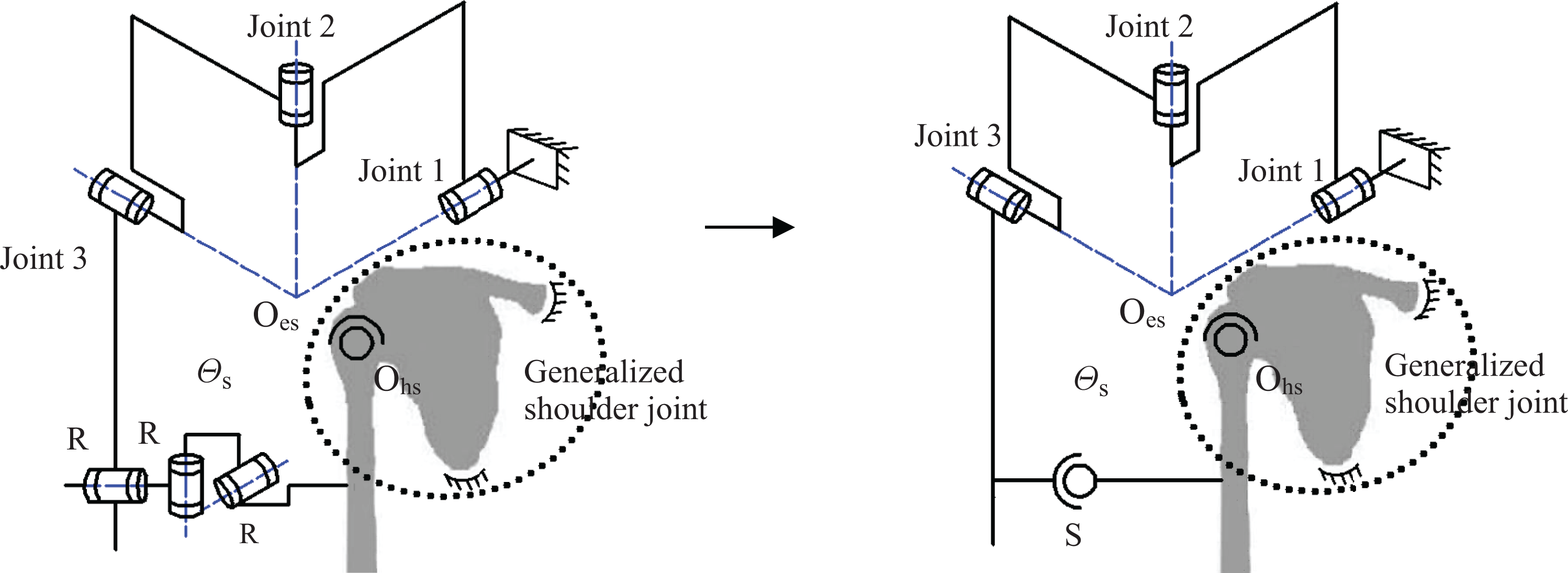
As an example, a four-DOF shoulder–elbow exoskeleton is shown in Figure 4(a). The shoulder joint has three active DOFs and comprises revolute joints 1, 2, and 3. The axes of these three joints are vertical and cross at the revolute center O
es. The elbow joint has one active DOF and is composed of revolute joint 4, and its axis is parallel to that of revolute joint 3. Consider the human–robot chain formed by this shoulder–elbow exoskeleton, the simple four-DOF kinematic model of human upper limb (the shoulder and elbow complexes are considered as a spherical joint with a fixed revolute center and a pure hinge joint with a fixed axis, as shown in Figure 4(b)), and the rigid connective units (the exoskeleton and the upper limb are connected by rigid cuffs at two positions on upper arm and forearm). If the exoskeleton joints are aligned with those of human upper limb (as shown in the solid line configuration in Figure 4(a), in which the two shoulder centers O
hs and O
es are coincident and the axes of the human and exoskeleton elbow joints are aligned with each other), then the human–robot chain corresponds to a four-DOF even-actuation system (i.e. the DOF number of human–robot chain equals the number of active joints), and the DOFs of the shoulder and elbow closed loops

Four-DOF shoulder–elbow exoskeleton and the corresponding human–robot chain. (a) Human–robot chain formed by the shoulder–elbow exoskeleton and human upper limb. (b) Shoulder and elbow joints of the shoulder–elbow exoskeleton. DOF: degrees of freedom.
Number synthesis method of the self-adapting upper-limb exoskeletons
In this section, the number synthesis method of self-adapting upper-limb exoskeletons is proposed. Specifically, the four- and five-DOF exoskeletons for shoulder–elbow and shoulder–elbow–forearm rehabilitation training are investigated. According to the motion features of human shoulder, elbow, and forearm complexes outlined in above section, the upper-limb kinematic models with generalized shoulder, elbow, and forearm joints are adopted to reflect the complicated human joint kinematics; that is, as a result of the motion coupling between joint rotations and axes (or center) movements in human joints, we consider the human shoulder, elbow, and forearm complexes to have three, one, and one independent DOFs, respectively. On the basis of such upper-limb kinematic models and the DOF analysis of spatial multiloop chains, the number synthesis of self-adapting upper-limb exoskeletons is eventually treated as an even-actuation synthesis problem of human–robot chains.
Basic chains of upper-limb exoskeletons
Figure 5 shows the schematic diagram of a human–robot chain formed by an exoskeleton and an upper limb without loss of generality. This human–robot chain is a spatial multiloop chain composed of the shoulder closed loop

General schematic diagram of a human–robot chain.
Knowing the number of DOFs and some components of the human–robot chains (the number of active joints in each independent closed loop and the kinematic model of human upper limb), how to determine the rest components (number and form of the added passive joints) through the even-actuation synthesis of the human–robot chains.
According to the study by Fang and Tsai, 34 the DOF of a multiloop chain can be calculated as

where F indicates the DOF of the multiloop chain, n denotes the joint number in the multiloop chain,
Accordingly, for the number synthesis issue of the self-adapting exoskeletons considered in this article, equation (1) can be rewritten as
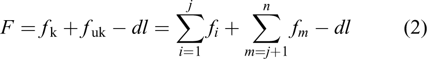
where
Because the DOF numbers of human–robot chains corresponding to the four-DOF shoulder–elbow and five-DOF shoulder–elbow–forearm exoskeletons are


Therefore, to construct even-actuation multiloop chains, eight and seven passive DOFs should be introduced into these two human–robot chains, respectively.
Note that both shoulder closed loops in the two human–robot chains are connected to the base and contain three one-DOF active joints; hence, each shoulder closed loop should have at least three DOFs. By means of Figure 5 and equation (1), the minimum


where
Moreover, because the sums of the DOFs of the unknown joints of the two human–robot chains are


Hence, if the maximum number of passive joints added into each independent loop is not larger than five (when the number is larger than five, it would not make any practical sense in application where force transmission is required 20 ), according to the results of equations (3) to (8), the numerical combinations of the basic joints that can be added into the shoulder, elbow, and elbow–forearm closed loops of the four- and five-DOF human–robot chains are obtained and classified into the following three and two groups, respectively


Eventually, the basic chains of the shoulder, elbow, and elbow–forearm subchains of the self-adapting four- and five-DOF upper-limb exoskeletons are synthesized and illustrated in Tables 1 to 5. For brevity, here the differences in the subchains with different installed joint sequences are not discussed. Moreover, to simplify their structures, the number of prismatic joints in each subchain is not larger than three. In Tables 1 to 5, Ra denotes the active joint of the shoulder, elbow, and elbow–forearm subchains, and R and P stand for the passive revolute and prismatic joints of the upper-limb exoskeletons, respectively.
Basic chains of the shoulder and elbow subchains of the (

Basic chains of the shoulder and elbow subchains of the (

Basic chains of the shoulder and elbow subchains of the (

Basic chains of the shoulder and elbow–forearm subchains of the (

Basic chains of the shoulder and elbow–forearm subchains of the (

According to Tables 1 to 5, the possible basic chains of the four- and five-DOF upper-limb exoskeletons can be constructed through the combination of the shoulder, elbow, and elbow–forearm subchains. However, an upper-limb exoskeleton must be formed by the subchains in the same group, and each shoulder (elbow or elbow–forearm) subchain can be combined with any of the elbow or elbow–forearm (shoulder) subchains. In addition, the positions of the passive revolute joint, prismatic joint, and active joint in the same shoulder, elbow, and elbow–forearm subchains are not restricted.
As the applications of Tables 1
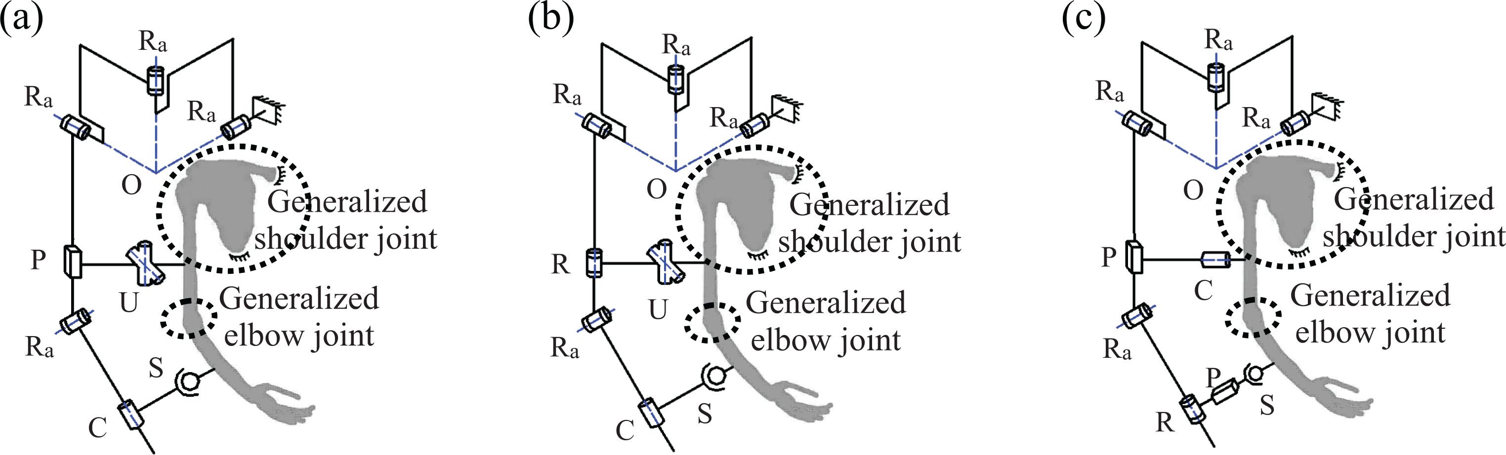
to 5, several different basic chains of the four-DOF shoulder–elbow and five-DOF shoulder–elbow–forearm exoskeletons, as well as their corresponding even-actuation human–robot chains, are illustrated in Figures 6 and 7, and these exoskeletons are formed by the shoulder, elbow and elbow–forearm subchains of groups (

Three basic exoskeleton chains of groups (

Two basic exoskeleton chains of groups (
Considering the human–robot chains shown in Figures 6(a) and 7(a) and assuming that the three active joints in the shoulder closed loops are locked, the two shoulder closed loops can no longer move, and the elbow and elbow–forearm closed loops have one and two DOFs, respectively. Under this condition, the training of the human elbow and elbow–forearm can be independently achieved with the motions of the elbow and elbow–forearm closed loops. Nevertheless, if the three active joints in the shoulder closed loops shown in Figures 6(b) and (c) and 7(b) are locked, then these shoulder closed loops still have one DOF, two DOFs, and one DOF, respectively. In these cases, the motions between the shoulder and the elbow (or the elbow–forearm) closed loops are coupled. Consequently, the training of the human elbow and elbow–forearm cannot be independently fulfilled with the motions of the elbow and elbow–forearm closed loops. In sum, the independent training of the human elbow and elbow–forearm can be realized with the exoskeletons of groups (
Simplified chains of upper-limb exoskeletons
On the basis of the shoulder, elbow, and elbow–forearm subchains given in Tables 1 to 5, the feasible simplified chains of the four- and five-DOF upper-limb exoskeletons are synthesized and enumerated in this section. The main emphases are placed on the quasi-anthropopathic aspect and the structural simplicity of the upper-limb exoskeletons.
The quasi-anthropopathic feature means that a similar structure of human upper limb is adopted as the major chain of an exoskeleton. In this case, the exoskeletons will have a similar workspace as that of an upper limb, and the active joints of exoskeletons and the human joints will gain an approximative one-to-one correspondence. In this study, the simple four- and five-DOF kinematic models of human upper limb are adopted as the major chains of the exoskeletons, with the shoulder, elbow, and forearm joints regarded as an active three-DOF spherical joint with a fixed revolute center and two active one-DOF hinge joints with fixed revolute axes.
For structure simplicity, the rest subchains in an exoskeleton should be short and simple. Note that a spherical joint and a universal joint are equivalent to three and two intersecting revolute joints, respectively, and a cylindrical joint is equivalent to a prismatic joint concurrent with a revolute joint; the rest subchains can be simplified in a way that several one-DOF basic joints are replaced with one multi-DOF joint.
When the simple four- and five-DOF upper-limb kinematic models are adopted as major chains, the shoulder, elbow, and elbow–forearm subchains presented in Tables 1 to 5 can be simplified through joint replacements; the corresponding subchains are illustrated in Tables 6 to 10. In Tables 6 to 10, S, U, and C denote the three-DOF spherical joint, two-DOF universal joint, and cylindrical joint, respectively.
Simplified chains of the shoulder and elbow subchains of the (

Simplified chains of the shoulder and elbow sub-chains of the (

Simplified chains of the shoulder and elbow subchains of the (

Simplified chains of the shoulder and elbow–forearm subchains of the (

Simplified chains of the shoulder and elbow–forearm subchains of the (

It can be seen that the more the basic one-DOF joints are replaced by the multi-DOF joints the shorter the shoulder, elbow, and elbow–forearm subchains become. For instance, the basic elbow subchain 1Ra5R in the third column of Table 6 corresponds to different simplified chains (the subchains 1Ra1S1U, 1Ra2U1R, 1Ra1S2R, 1Ra1U3R in columns 4, 5, and 5, respectively), and 1Ra1S1U is the shortest one among them. However, it is worth note that the joint replacement should ensure the even-actuation of human–robot chains. As an example, consider the shoulder subchain 3Ra3R of groups (
An invalid simplified chain of the 3Ra3R shoulder subchain of groups (
Through the connections of the shoulder, elbow, and elbow–forearm subchains given in Tables 6
to 10, the feasible simplified chains of the self-adapting four- and five-DOF upper-limb exoskeletons can be directly constructed. As examples, several simplified chains formed by the subchains of groups (
Simplified chains of the shoulder–elbow exoskeletons of group (

Simplified chains of the shoulder–elbow exoskeletons of group (

Simplified chains of the shoulder–elbow exoskeletons of group (

Simplified chains of the shoulder–elbow–forearm exoskeletons of group (

Simplified chains of the shoulder–elbow–forearm exoskeletons of group (
Considering the simplified chains illustrated in Figures 9
to 13, it is known that they all satisfy the request of condition (1), because the active joint number in anyone of them equals its DOF number, respectively. According to condition (2), the chains in Figures 9(a), 10(a) to (c), 11(a) to (c), 12(a) to (b), and 13(a) and (c) are selected, since the interactional force along human limbs’ axes could be reduced by the passive joints having prismatic DOF along exoskeletons’ limb axes (e.g. the P and C joints in Figure 9(a)). Finally, in response to the request of condition (3), the chains shown in Figures 9(a), 10(a), 11(a), 12(a), and 13(a) could be selected as the better simplified ones among the enumerated exoskeletons of groups (
Discussion and future works
In the design of exoskeletons for rehabilitation application, one critical issue is the avoidance of the UI loads caused by the axes misalignments between exoskeleton and human joints. At present, axes self-aligning method is regarded as a suitable solution. The exoskeletons designed with this approach can withstand large axes misalignments and be worn by wearers with no need for manual adjustments. In this work, according to the positions of the additional joints installed in exoskeletons and the axes trajectory feature of exoskeleton active joints, we classed the self-aligning exoskeletons into two categories (the self-tracing exoskeletons and the self-adapting exoskeletons) and proposed a number synthesis method for the self-adapting exoskeletons. In our work, the wearing error and the variability of human joint axes around their supposed locations were analyzed, and the generalized three-DOF shoulder joint model, the one-DOF elbow joint model, and one-DOF forearm joint model were proposed. In these generalized joint models, the three DOFs of the shoulder GH joint, one DOF around the elbow F/E axis, and one DOF around the forearm P/S axis were treated as independent DOFs of human joints; the motions of the center of the GH joint, the elbow F/E axis, and the forearm P/S axis are not individual but are parasitical movements of the rotations of the aforementioned independent DOFs. Through these generalized joint models, the four- and five-DOF upper-limb kinematic models with variable axes joints were proposed. Motivated by these studies, we treated the number synthesis of the self-adapting exoskeletons as an even-actuation synthesis problem of human–robot chains and proposed an effective synthesis method on the basis of the conventional DOF analysis theory. This method is general and simple and applicable when the exoskeleton does not replicate human limb kinematics (e.g. the basic chains of upper-limb exoskeletons shown in Tables 1
to 5). Furthermore, through the suitable arrangement of the additional joints in human–robot chains, the method can also be used to synthesize the chains of self-tracing exoskeletons. For example, Figure 14(a) shows a basic chain of the four-DOF self-adapting upper-limb exoskeletons (the basic chain 3Ra2R1P + 1Ra3P2R of the (

A self-adapting upper-limb exoskeleton and its corresponding self-tracing exoskeleton. (a) The self-adapting exoskeleton (b) The self-tracing exoskeleton.
With this study, we have also proposed the feasible simplified chains of the four- and five-DOF self-adapting upper-limb exoskeletons, in which the simple kinematic models of human upper limb were adopted as the main chains of exoskeletons and the one-DOF basic joints were substituted with appropriate multi-DOF joints. The simplified chains have the benefits of the quasi-anthropopathic feature and structure simplicity; hence, they can be used as the candidates of self-adapting upper-limb exoskeletons. However, it is worth to note that due to the multiformity of the simplified chains of upper-limb exoskeletons (corresponding to the variability of connective subchains), studies on the kinematics and force transmission character of human–robot chains, the performance index definition, wearing comfort analysis, and the comparative study and optimal chain selection of different simplified chains are still needed to be devoted and will be addressed in future works.
Conclusions
The human–robot kinematic incompatibility of upper-limb exoskeletons was analyzed from an over-actuation perspective, and it is known that the UI loads are caused by the over-actuation of human–robot chains. Therefore, to remove these unwanted loads, the exoskeletons should be capable of generating even-actuation human–robot chains when connected to human upper limbs. An effective method for the number synthesis of self-adapting upper-limb exoskeletons was proposed with Hunt’s DOF formula and the conventional DOF analysis approach of spatial multiloop chains. The presented method is universal and simple; it is applicable when the exoskeleton does not replicate upper-limb kinematics and can also be applied to other kinds of human limb exoskeletons. The basic chains of the four- and five-DOF self-adapting upper-limb exoskeletons were proposed and classified, respectively, into three and two different groups. Feasible simplified chains of self-adapting upper-limb exoskeletons featuring the quasi-anthropopathic aspect and structure simplicity were synthesized, and they can be adopted as the candidates in further studies on the chain compare and selection and structure design of self-adapting upper-limb exoskeletons.
Footnotes
Declaration of conflicting interests
The author(s) declared no potential conflict of interest with respect to the research, authorship, and/or publication of this article.
Funding
The author(s) disclosed receipt of the following financial support for the research, authorship, and/or publication of this article: This work was supported by the National Natural Science Foundation of China under grant nos 61273342 and 51675008 and by the Beijing Natural Science Foundation under grant no. 3171001.