
Abstract
Robotic animals are nowadays developed for various types of research, such as bioinspired robotics, biomimetics, and animal behavioral studies. The design of these robots poses great challenges as they often have to achieve very high-level performances in terms of locomotion, size, and visual aspect. We developed a robotic system for direct underwater interactions with small fish species. This robotic platform is composed of two subsystems: a miniature wheeled mobile robot that can achieve complex locomotion patterns and a robotic fish lure that is able to beat its soft caudal peduncle to generate fish-like body movements. The two subsystems are coupled with magnets that allow the robotic lure to reach very high speeds and accelerations, thanks to the mobile robot. We used zebrafish (Danio rerio) to model small fish locomotion patterns and construct a controller for the motion of our robotic system. We have demonstrated that the designed system is able to achieve the same types of motion patterns as the zebrafish while mimicking the body movements of the fish. These results define new standards for robotic fish lures and bring to the field of fish–robot interaction a new tool for ethological studies.
Introduction
It is common nowadays to use robotic devices to study the behavior of animals, both in their natural environments 1 and in laboratory research. For instance, robotic platforms were socially integrated into a society of cockroaches, where they emitted pheromones and reproduced the motion behavior of cockroaches 2 ; they were also introduced into a group of chicks using a filial imprinting mechanism 3,4 ; or designed to mimic the honeybee dance communication system by generating wing oscillations and heat. 5
The collective behavior of the fish, in particular, raised the interest of scientists, and several examples of automated lures designed to interact with fish underwater can already be found. For instance, in earlier studies, 6 –8 zebrafish (Danio rerio) response to a robotic fish was observed. The robotic fish, which had the same aspect ratio as the zebrafish, was attached to a moving device on top of a tank and its speed could be varied, as well as the tail beating and its coloration. A study by Phamduy et al. 9 measured the preference of fertile female bluefin killifish (Lucania goodei) for a robotic replica whose aspect ratio, body size, motion pattern, and color were inspired by an adult male killifish using a robotic platform specifically designed to simulate the typical courtship behavior observed in male killifish. In the studies by Marras and colleagues, 10 –14 a passive lure attached to a support was moved using a mobile robot below the aquarium and controlled using a tracking software. In a study by Worm et al., 15 a mobile robot was also used to move a robotic lure, which emitted electrical playback signals to attract the weakly electric fish (Mormyrus rume). While these different studies demonstrated the potential to develop artificial devices that are able to interact with fish, there is no solution involving an active lure with size close to the size of the fish that can reproduce the pattern motion of the fish and autonomously move in an aquarium to integrate a shoal of fish.
With regard to the bioinspired research applied on fish-like robots, there is a trend to apply new types of actuators for the development of small-scale biomimetic fish robots. 16 –20 Even if this allows high levels of performance to be achieved in terms of size, tail beating frequencies, or energy consumption, these actuators have several drawbacks, such as temperature sensitivity for shape-memory alloys and specific liquid environment requirements for electroactive polymers which can pose challenges to the design of an autonomous and miniature robotic fish. Moreover, it is sometimes difficult to embed the electronics into the devices due to the size of the components required to drive the different actuators; so either the fish need to be rather big or the electronic need to be partially external which reduce the autonomy of the system.
Regarding the embodiment of fish locomotion on a robotic device to reproduce fish behavior, few models of fish locomotion can be found in the literature. For instance, in a study by Mwaffo et al., 21 fish locomotion is modeled using a jump persistent turning walker model motivated by the sudden and drastic changes in zebrafish locomotion in the form of large deviations in turn rate. Zienkiewicz et al. 22 used a stochastic model to reproduce zebrafish locomotion in a confined environment. While these models accurately reproduce the motion of fish, the translation of their mathematical expression in concrete commands for a robot was not validated on a real system.
In this article, we present the combination of two robotic modules: a highly maneuverable wheeled robot, prototyped versions of which were presented in the studies by Bonnet and colleagues, 23,24 and an actuated robotic fish lure designed using a biomimetic approach. It allows robots to navigate inside species of small fish shoals at very high speeds and with multiple robotic agents while reproducing specific fish body movements which has not been achieved in related studies yet. In this study, we use the zebrafish as a model animal, but this system could be also used to study the behavior of other types of small freshwater fish, such as guppies, golden shiners, or sticklebacks. A controller based on data extracted from experimental zebrafish trajectories is implemented on the robotic device to reproduce their locomotion patterns. Finally, we show the matching of the locomotion pattern of our robot with that of the zebrafish using the information retrieved by a vision-based tracking system to qualify our implementation.
The capabilities of this new robotic platform will help scientists to better understand the type of interactions between small species of fish that lead to the formation of shoaling and to collective choices.
Hardware design
The robotic platform presented in this research is called Fish-Control-Actuator-Sensor-Unit or Fish-CASU. The Fish-CASU is composed of two modules: a wheeled mobile robot, the FishBot, that is able to achieve high speeds and accelerations while performing local obstacle avoidance using infrared (IR) proximity sensors and an actuated bio-inspired fish lure, the RiBot, that is equipped with a beating caudal peduncle to reproduce fish body movements. The two modules are coupled with magnets that allow the RiBot to follow a shoal of fish swimming at high speed while moving its body similarly to the fish. The hardware design of the two modules will be described separately in the next subsections, followed by the experimental setup used to perform the biological experiments on zebrafish.
FishBot, the high-speed miniature mobile robot
The design of the FishBot was driven by the following requirements: the robot should achieve linear speed and acceleration similar to the zebrafish, and it should allow multi-robot, long duration experiments. Thus, its width and length should not exceed that of zebrafish to allow the shoaling of Fish-CASUs, and it should be continuously powered. Some prototyped versions of the FishBot were already introduced in literature, 23,24 but we still have improved the maneuverability of the device to fit the specifications to conduct this study.
A differential drive configuration with two independently motorized wheels was adopted for the locomotion. It is enough to mimic the zebrafish locomotion in 2-D as they usually only move with a tangential speed and no lateral speed. In terms of rotational speed, due to the differential drive configuration and the small distance between the two wheels, the FishBot can also have very high capacities which are enough to mimick the rotational motions of zebrafish. Two DC motors (Maxon Motor AG, Sachseln, Switzerland) are used to drive the two robot wheels through a worm gear transmission of 16:1 reduction ratio.
The current version of the FishBot is presented in Figure 1. The length of the mobile robot is 55 mm, the width 22 mm, and the height 53 mm. The mass of the FishBot is 80 g. The power supply is done through electric cables (brushes) that slip against two conductive plates situated under the aquarium floor (positive voltage) and on the support on which the robot moves (ground; Figure 4). Supercapacitors are used in order to store energy in case the brushes are not in contact with the conductive plates for a couple of seconds to allow the continuous powering of the robot. Six IR proximity sensors are installed on the front and back of the robot in order to avoid obstacles, other FishBots, or the border of the arena. A Bluetooth antenna is used for wireless communication to control the robot.
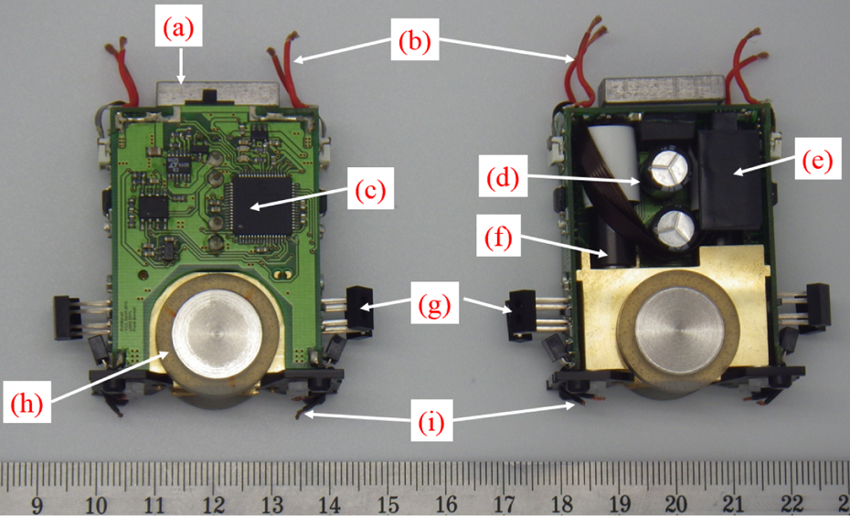
Current version of the FishBot used for mimicking fish motion patterns. (a) Magnets to couple the FishBot with the lure module; (b) electric brushes to retrieve the power from the positive conductive plate; (c) microcontroller dsPIC33f128; (d) supercapacitors that store power if the contact with the plates is lost; (e) Bluetooth antenna; (f) Maxon DC motor; (g) infrared proximity sensors; (h) wheel; (i) electric brushes to retrieve the power from the ground connected conductive plate.
An ASEBA virtual machine runs onboard each mobile robot. ASEBA 25 is an event-based architecture for the real-time distributed control of robots. The ASEBA communication protocol allows multiple robots to connect on the same network. This allows them to share global events that can be sent via a high-level control application or by the robots themselves. ASEBA, integrated with D-Bus, allows access to each robot using high-level programming languages (such as C++, Python, or ROS) via a software hub called Medulla. 26
In order to increase the capabilities of the robot to mimick the locomotion of zebrafish in terms of speed and acceleration, a cascade controller (Figure 8) is implemented for the low-level control of each motor. Each motor torque is controlled by a proportional–integral (PI) controller running at 1 KHz, which is itself controlled in speed by a proportional–integral–derivative controller or in position by a proportional–derivative controller using the motor encoders. An infinite impulse response (IIR) filter with the same time constant as that of the motor is run on the microcontroller. By precisely controlling the current inside each motor, based on the estimated power dissipation from the IIR filter, we are able to ensure that we never overheat the motor. Such control architecture enables us to use the motors at voltages higher than the manufacturer-specified nominal voltage, thus providing a higher torque for a short period of time.
RiBot, the active soft robotic lure
Based on related studies on zebrafish–robot interactions, 6 –8 the lure acceptance among the zebrafish shoal can be increased when the lure beats its tail. It is also known that zebrafish can bend their caudal peduncle up to very high angle (up to π rad) with high angular velocities (up to 4.2 rad s−1). 21 Therefore, we designed an actuated lure able to emit such tail beating stimulus. While the beating of the tail could have been generated passively using the water flow generated by the motion of the lure, we developed an actuator inside the lure to actively control the tail beating. This actuator placed inside the lure allows us to determine the frequency and amplitude of the tail beating independently from the motion of the lure. This device has to be wireless and waterproof, have a low power consumption, and should fit inside a small lure since zebrafish rarely exceeds 45 mm in length.
The design of the RiBot involved the use of a printed circuit board (PCB) on which all the electronic components are soldered. As PCB also has very interesting mechanical properties, the PCB also forms the skeleton of the device, combining in this way mechanical and electronic structures to reduce the size and weight of the system. The RiBot is equipped with a rechargeable lithium polymer (LiPo) battery of 40 mAh capacity with a size of 12 × 16 × 5 (mm). An IR sensor is placed on the back of the RiBot, and an IR signal can be sent from any direction to control the device underwater. For the actuation of the caudal peduncle, we chose the microstep gear motor MF03G (Seiko Precision Inc., Matsudo, Japan). This stepper motor has enough torque to drive the caudal peduncle underwater.
Figure 2 shows the manufacturing steps of the RiBot. The motor with the caudal peduncle docked on its axis is fixed inside a 3-D part, called the ring as it has an elliptical external shape, that is glued onto the PCB. A LiPo battery of 40 mAh capacity is soldered onto the eye of the RiBot, which will then be used to recharge the device. In order to isolate the actuator and the caudal peduncle from water and to create a soft skin that can mimic the tail of the zebrafish, an undercut of the tail was made in 3-D printing and was dipped into liquid latex. The skin created was unmolded and attached on the ring using silicone. The caudal fin is also made of latex and is prepared separately from the tail using another mold, and it is glued onto the tail using latex. Polyurethane is used to isolate the electronics from the water. The PCB is placed inside a mold with the desired undercut of the RiBot, and the eyes are used as a reference inside the mold. Liquid polyurethane is injected inside the mold from the tail. The polyurethane coats the entire PCB up to the ring and hardens inside the mold. For the shape design of the molds used to manufacture the latex tail and the polyurethane body, we used surfaces extracted from a 3-D scan of a zebrafish. The surface of the skin was extracted and increased by the proper ratio to match the size of the PCB. After this process, the RiBot is totally isolated from water.

Process of the RiBot manufacturing. (a) The stepper motor and the eyes are soldered onto the PCB. (b) The battery is placed and connected to the eyes. The caudal peduncle is fixed to the stepper motor axis and a ring is placed on the stepper motor. (c) A latex socket is placed and glued using silicone onto the ring to isolate the back of the fish from water and reproduce the caudal fin skin. (d) The RiBot is put inside a mold and polyurethane is injected into it. The polyurethane covers all the rest of the body so that the device is totally waterproof. PCB: printed circuit board.
A comparison of a prototype version of the RiBot with one of our zebrafish is shown in Figure 3. The RiBot has a mass of 9.0 g and sinks beneath the water surface due to its density. It was not possible with the selected components to obtain a robot with the same scale as the zebrafish, thus the current design has a 1.8 ratio compared to the zebrafish. In terms of autonomy, we performed a 24-minute test with the caudal peduncle of the RiBot moving continuously using the embedded LiPo battery; however, upon reducing the use of the actuator, the RiBot remained turned on for more than 1 h underwater. This allowed us to perform hour-long experiments with the Fish-CASU. Both polyurethane and latex surfaces can be painted in order to mimic the fish colors, as it was done in the study by Abaid et al. 6

The RiBot compared with one of our zebrafish. This figure shows the 1.8 ratio between the lure and a real zebrafish. The RiBot is mounted on a base composed of a tiny carbon stick and an iron plate. Magnets are attached to the iron plate to magnetically couple the RiBot with the FishBot. Here, we used zebrafish as a model animal, but the RiBot could also be adapted to study the behavior of other small freshwater fish, thanks to its small size.
The experimental setup
The experimental setup used for the experiments consists of an aquarium of 1000 × 1000 × 200 (mm) covered on the inside with white Teflon sheets (Figure 4). These sheets are installed in order to avoid reflections on the glass and to provide a smooth surface for the motion of the lure module inside the aquarium. The structure is supported by a rigid structural aluminum framing system, which is exposed to diffused light in order to reproduce daylight. The tank is filled with water up to a level of 60 mm. The FishBots are powered using two conductive plates, one glued onto the bottom of the aquarium and one onto the support on which the robot moves. An overhead acA2040-25gm monochrome GigE CCD camera (Basler AG, Germany) with a maximum resolution of 2048 × 2048 (pixels) and equipped with low distortion lenses CF12.5HA-1 (Fujinon, Tokyo, Japan) grabs frames that are then processed for tracking purposes. An IR light-emitting diode is placed on top of the setup to control the RiBots. It is connected to the output of a Raspberry PI that is interfaced with the main desktop computer. The RC5 IR signals are generated using the Linux IR Remote Control (LIRC) library on the Raspberry PI.
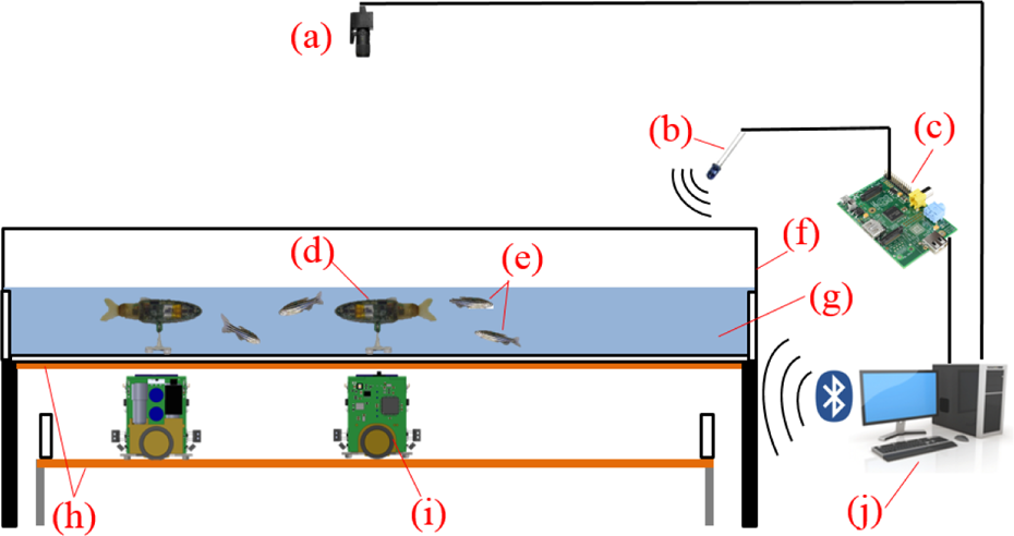
Experimental setup used during the experiments. (a) Camera used to track the lures and the zebrafish; (b) infrared emitter; (c) Raspberry Pi; (d) RiBot inside the aquarium linked to a FishBot through magnetic coupling; (e) living zebrafish; (f) aquarium of 1000 × 1000 × 250 (mm); (g) water layer of 60 mm depth; (h) conductive plates to power the mobile robot; (i) FishBot moving under the aquarium; (j) the computer that processes the camera frames and remotely controls the robots via Bluetooth and infrared RC5 protocol.
Comparison of the Fish-CASU with related work on fish–robot interaction
The designed system described in this section brings several new assets compared to existing published solutions: the multi-robot long duration experiments and the small size of the robotic lure that is in direct contact with the fish.
Multi-robot experiments
In order to reproduce the motion of a fish shoal using robotic devices, the robots have to move very close to each other, thus should have very small size. With the proposed solution, we can run multi-robot experiments with a large number of robots moving in every possible directions that cannot be achieved by the methods presented in the studies by Faria et al. 11 and Phamduy et al. 9 However, these types of experiments are also possible with the approach of the studies by Landgraf and colleagues 12 –14 that also use a differential drive mobile robot to move a dummy fish underwater through magnetic coupling. However, comparing the size of the mobile robots, Landgraf et al. 12,13 used a mobile robot of 70 mm of length and 70 mm of width, while Swain et al. 14 used the MiaBot 27 that has a length and a width of 75 mm, thus the distance between two dummy fish will be of 70 mm in minimum for the first case and 75 mm for the second case. With the FishBot, thanks to it width of 22 mm, it is possible to have two lures moving at a distance of 22 mm, thus much closer to natural inter-fish distances. This is one of the main advantages of the FishBot compared to other robots. Moreover, the robots are also equipped with IR proximity sensors that can be used to avoid any collisions between the FishBots.
Long duration experiments
Another advantage is the continuous powering of the system. Indeed, the robotic devices used in the studies by Landgraf and colleagues 12 –14 are powered using onboard batteries. With our proposed design, the powering of the mobile robot is continuous, which offer experiments that can last up to several days if using a passive lure such as the lures proposed in the studies by Landgraf and colleagues 12 –14 or RiBot without the continuous actuation of the tail.
Small-size actuated lure
Table 1 shows a comparison of the RiBot with other actuated robotic lures designed in other studies on fish–robot interaction. In terms of size, we have smaller length, width, and height compared with other robotic fish designs while respecting more the shape ratio of a zebrafish. Finally, in terms of linear speed, in a study by Aureli et al., 7 the lure is moving autonomously underwater and thus its linear speed is quite small. In a study by Butail et al., 8 the lure is attached to a robotic arm that allows it to move with speeds up to 40 mm s−1. Thanks to the coupling with the FishBot, the RiBot is able to move with much higher speeds than the other existing solutions.
Comparison of the size and linear speed of the fish robots presented in other similar studies.

Control and tracking software
In order to retrieve the position of the agents (fish and Fish-CASUs) during an experiment and to control the Fish-CASU, we have implemented a vision-based tracking in our control software that processes the frames grabbed by the upper camera of the experimental setup. A background subtraction is performed on each frame to extract the moving objects. Then we detect the head of each agents using a corner detection methods that is described in a study by Shi and Tomasi. 28 The poses of the RiBots are used to estimate the poses of the FishBots for their closed-loop control. The beating of the RiBot caudal peduncle is also controlled by this application.
In terms of global architecture (Figure 5), the control of the FishBots motion is done through ASEBA events that are sent from the main application and that contain the parameters for the locomotion. The behaviors that will be described in the next section are implemented onboard each FishBot. Thanks to the event-based protocol, the FishBots are able to emit events in case of obstacle presence or powering issues. The detection of obstacles is done using the IR proximity sensors: when an IR signal received by the sensors is higher than a certain threshold, the FishBot avoid the obstacle by turning with a certain amount of time in the opposite direction of the received signal. It allows the FishBot to avoid the collisions with the walls as well as other FishBots.

Architecture of the Fish-CASU vision-based closed-loop control. The high-level control-software tracks each RiBot and fish using frames grabbed by a camera. The same software is used to control the FishBots motion as well as the RiBots body movements. Each RiBot and each FishBot can be controlled individually. For the FishBots, the desired speed of each wheel is sent through a serial connection using Medulla integrated with D-Bus on the ASEBA network, where all the FishBots are connected and can receive or emit events. For the RiBots, the communication is only one way, where the IR RC5 signal is broadcasted to control stepper motors that drive the caudal peduncles.
A Raspberry PI, on which LIRC library is run, is connected to the same network as the main computer, and RC5 signals are generated on an output pin connected to an IR emitter in order to control the RiBots. The IR signal is broadcasted on the whole aquarium and received by all the RiBots.
The tracking and control application was also used to analyze the locomotion of the agents. Using the positions of the agents moving inside of the aquarium, retrieved by the tracking, we could compute the speeds knowing that the tracking was done at 15 frames per second. We computed the linear and angular speed using the position difference between three frames instead of two frames in order to average the noise given by the tracking.
Locomotion pattern embodiment
Ethics statement
The experiments performed in this study were conducted under the authorization No 2778 delivered by the Department of Consumer and Veterinary of the Canton de Vaud (Switzerland) and the Buffon Ethical Committee (registered to the French National Ethical Committee for Animal Experiments #40) after submission to the French and Swiss state ethical board for animal experiments.
Animals and housing
To characterize the locomotion pattern of zebrafish, we observed 10 adult wild-type zebrafish (Danio rerio) AB strain acquired from Institut Curie (Paris, France). The fish were 18 months old at the time of the experiments. We kept the fish under laboratory conditions, 27°C, 500 μS salinity, with a 10:14 day–night cycle. The fish were reared in 55 l tanks and fed two times a day (Special Diets Services SDS-400 Scientific Fish Food). The water pH level was maintained at 7.5, and nitrites (NO−2) were below 0.3 mg l−1.
Zebrafish locomotion analysis
Zebrafish were individually transferred from their housing aquarium to the experimental aquarium to extract the characteristics of their trajectories over time. We recorded, at 15 frames per second, the position of each fish swimming alone in the tank for 1 h. Thanks to this tracking, we retrieved the trajectory of each fish and computed their speed and acceleration during the entire experiment. An example of a trajectory is given in Figure 6(a) and highlights that the fish were mainly swimming along the walls of the tank, as also shown by Zienkiewicz et al. 22 We could also identify three speed patterns of the fish according to their location in the experimental tank. Indeed, their linear speed decreases in the corners of the tank when they change their direction, while the zebrafish swim at a higher speed along the edges of the tank. Finally, we measured the highest linear speed values in the middle of the aquarium. Thus, we divided the experimental tank into different zones: corners, edges, and the center (Figure 6(b)). The distance d delimiting the edges and the corners was estimated at 15 cm.
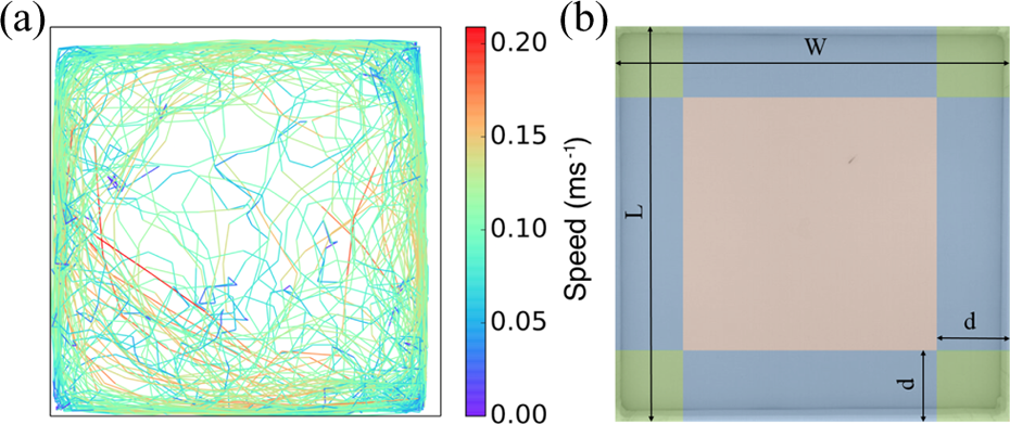
(a) The trajectory of a zebrafish swimming in the experimental tank for 1 h. The color of the trajectory indicates the linear speed of the fish at a given position (Δt = 1 s). The fish is mainly observed along the wall of the tank and decreases its speed in the corners of the tank, while higher speed values are measured in the center of the aquarium. (b) Zone delimitation in a tank of L (100 cm) and W (100 cm) for the three different types of fish behavior extraction: corners (green) that are delimited by the right angle walls of the tank and virtual lines at a distance d (15 cm) from the walls, edges (blue) delimited by the setup wall and the same virtual line, and the center (red). The motion patterns of the fish were classified depending on the presence zone.
As our goal is to develop a modular robotic system that mimics fish locomotion, we also performed a more detailed analysis of the characteristic motion pattern of the fish. The speed of the fish can be decomposed into successive cycles, starting with a sharp acceleration followed by a slow deceleration until the next tail beat (Figure 7(a) and– (b), left). With regard to the direction of the fish, the changes in orientation, identified by a high angular speed, are mainly detected at the beginning of the cycle (Figure 7(c), left). Thus, the zebrafish usually move by following a sequence of three steps:
Step 1: Orientation. Strong caudal peduncle bending to reorient and start the propulsion toward the next goal.
Step 2: Acceleration. High linear acceleration following the given caudal peduncle beating to reorient.
Step 3: Relaxation. Tail beating stops and the fish starts sliding into water with its linear speed decreasing.

Left: Example of the characteristic swimming behavior of a zebrafish magnified for 3 s. Each colored segment represents the linear speed (a), acceleration (b), and angular speed (c) of the fish measured at a given position (Δt = 1/15 s). The linear speed of the fish can be decomposed into cycles that start by a sharp acceleration (hot colors) followed by a longer deceleration (cold colors). The angular speed highlights that changes of orientation occur mainly at the start of the cycles. Right: Finite-state machine implemented on the control layer of FishBots. A motion cycle is started when an event is received from the high-level control application. The parameters contained on the event are used in the different steps: Δθ is the angle difference between the current orientation of the RiBot and the orientation needed to reach the next target, Pt is the target position to accelerate, and Vt is the target linear forward speed. If an obstacle or another robot is detected during a cycle, a simple obstacle avoidance behavior is implemented to avoid it until a new event is received.
Implementation on the Fish-CASU
We implemented a finite-state machine into the robot controller in order to execute the same locomotion sequence as the zebrafish (Figure 7, right). An event containing the ID of the FishBot is emitted with a parameterized frequency from the control application and sent to the ASEBA network on which all the FishBots are connected. When an event is received by a FishBot, it starts executing the finite-state machine with the three locomotion steps described: orientation, acceleration, and relaxation. In case of an obstacle detected by the IR proximity sensors, the execution of the locomotion is stopped and the robot starts avoiding the obstacle, and then return to the relaxation state where it waits for a new event.
For step 1, the orientation, we used the wheels position control to reorient the robot toward the target with an orientation difference of Δθ. We used one wheel of the robot to move forward while the other wheel remained stationary. This generates a rotation of the robot with a small linear speed, as zebrafish almost never have a null linear speed even while turning.
For step 2, the acceleration, as we have no direct control over the acceleration (Figure 8), we measured the acceleration obtained using the position control in cascade with the speed and current control. By using the cascade controller, the motors are protected against overheating or too high speeds, and we can adjust the position controller gains to obtain very high acceleration. The measures are shown in Figure 9 (left); we can see that the increase in acceleration is linear with the target position Pt ordered up to 6 cm, where the maximum FishBot acceleration of 1.3 m s−2 of average was achieved. After that, the motors entered in saturation due to the limit of the system. The linear curve of this figure was used to match the acceleration of the FishBot with the acceleration of the zebrafish. We have also characterized the limits of the system in terms of speed (Figure 9, right). We can observe that for speeds of up to 20 cm s−1, the response is relatively smooth and stable. For higher speeds, the robot takes more time to reach the desired command, and over 30 cm s−1, the limit of the system is achieved. Finally, in terms of angular speed, the FishBot alone is able to achieve angular speed of up to 30 rad s−1. However, the magnetic coupling between the RiBot and the FishBot was lost over speeds of 18 rad s−1.

Control architecture of the FishBot motors. A PI current controller is running at 1 KHz. The motor encoders retrieve the position of the motor that is used in a PID speed control loop and PD position control loop at 200 Hz. The user can choose between position or speed control of the motor.

Left: Fish-CASU acceleration measured as a function of the position to reach using a PD position control. Right: Fish-CASU speed measured as a function of the speed to reach.
Finally, for step 3, the relaxation, we used the speed controller to generate a linear forward speed Vt of the robot, which decreases over time at a rate of 1 cm every 100 ms (10 cm s−1), thereby reproducing the deceleration of the zebrafish.
Experiments with the Fish-CASU
Regarding the matching of locomotion, we tuned the parameters of our fish locomotion behavior implemented on the FishBot to match the data extracted from the zebrafish locomotion patterns. The final parameters of the Fish-CASU are shown in Table 2. These parameters were tuned in order to match the average linear speeds and, secondarily, the locomotion sequence curve in terms of speed and acceleration (Figures 11 –13).
The parameters of the locomotion of the Fish-CASU for the three zones of the experimental setup.a

F: the frequency at which the ASEBA events are sent to start a motion cycle; Pt : the target position to mimic the acceleration phase; Vt : the starting linear speed for the relaxation phase.
We recorded, at 15 frames per second, the position of the Fish-CASU moving alone in the tank for 1 h using the same experimental setup and tracking software used to analyze zebrafish movements. The Fish-CASU was programmed to follow a trajectory similar to the zebrafish by following the walls and, from time to time, moving rapidly in the center of the tank.
Results and discussion
Figure 9 shows the tracking result of the FishBot for different speeds and accelerations. In respect to the existing literature, the FishBot has very high capacities in terms of acceleration (up to 1.3 m s−2), linear speed (up to 30 cm s−1), and rotational speed (more than 18 rad s−1).
We also tracked the tip of the caudal fin of the RiBot in order to measure the tail beating frequencies and amplitudes (Figure 10). The RiBot has limited amplitude and frequency capabilities that restrict it from reproducing some of the extreme body movements of zebrafish, which can bend their caudal peduncle more than π/2 rad (90°) with an angular speed over 4 rad s−1; with the maximal beating amplitude of the RiBot is 0.52 rad (30°), and the maximal angular speed is 3.6 rad s−1 but for very low amplitudes. However, the RiBot is able to reproduce the average turn rate of the zebrafish (approximately 2.8 rad s−121) for an amplitude of 0.32 rad (18.35°), as it can be seen in Figure 10.
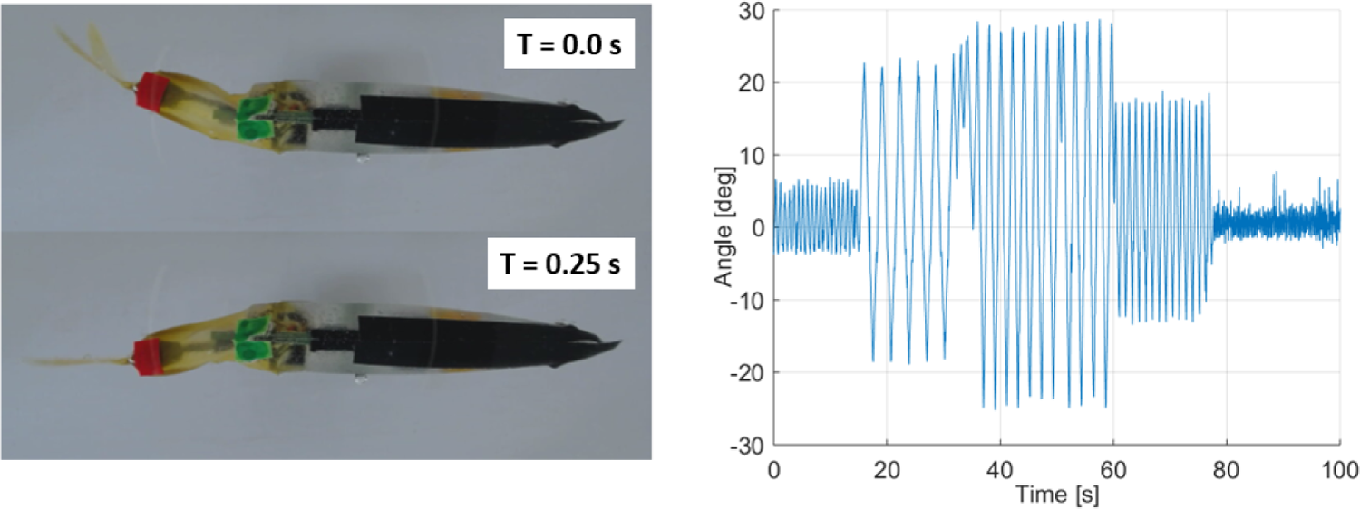
Left: Top view of the RiBot beating its caudal peduncle. Right: Results of the tracking of the caudal fin for different beating amplitudes and frequencies.
The distribution of the linear speed measured in the three zones of the tank (corners, edges, center) is shown in Figure 11 for the Fish-CASU and the zebrafish. As suggested by preliminary observations, the fish swim with a higher speed near the edges (0.054 ± 0.032 m s−1) than in the corners (0.066 ± 0.034 m s−1) of the tank and even faster in the center of the aquarium (0.073 ± 0.031 m s−1). By adjusting the parameters of the controller, we were able to reproduce similar distributions between the Fish-CASU and the zebrafish. However, the fitting quality of the speed distribution is lower in the case of the Fish-CASU for motions along the edges and in the center, which is not the case for the zebrafish. This can be explained by the fact that for high accelerations that are applied in order to achieve high average speeds, the Fish-CASU is less regular than the zebrafish due to the friction of the lure module, the slipping of the FishBot wheels, and the inertia of the system.
In addition, with the developed controller, the Fish-CASU was able to reproduce the sinusoidal shape of the speed and acceleration of the fish (Figure 12). This is made possible by fitting the movement patterns of the fish with the movement patterns of the robots. By identifying successive local minima in the linear speed of the fish, we computed the average speed cycle of the fish as well as the corresponding acceleration. As previously shown, the sequence begins with a short acceleration during 2/15 s, and once the fish has reached its maximum speed, it glides and slows down to return to its initial speed (Figure 13(c) and (d)). The Fish-CASU can mimic relatively well the motion pattern of the zebrafish. The mean speed obtained, as already shown in Figure 11, is similar. The initial speed is smaller in the case of the Fish-CASU than for the fish; this is explained by the friction of the lure module on the aquarium floor. The standard deviations are relatively similar, which shows that the robotic platform can reproduce well the typical locomotion patterns of a zebrafish.

Speed density for the motion of an agent, Fish-CASU and zebrafish over the span of an hour in the three different zones of the aquarium: corners, edges, and center.
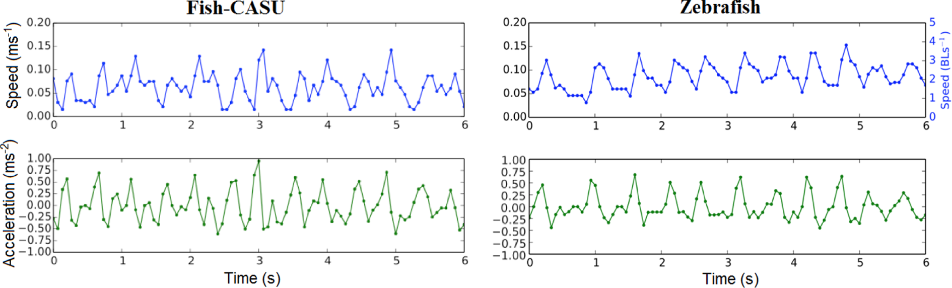
The typical speed and acceleration of an agent, Fish-CASU and zebrafish, movements in a corner of the aquarium recorded over 6 s.

The average agents movement sequence for movement along the edges of the experimental tank. Linear speed (a and c) and acceleration (b and d) of the Fish-CASU and the zebrafish during the speed cycle. The cycle begins with a short acceleration (2/15 s) until the agent reaches its maximum speed, then it decelerates by gliding in the water until the next tail beat.
Conclusion
In this article, we presented a modular robotic fish designed for animal behavior studies, the Fish-CASU, which is composed of two units: a FishBot, a fast-moving wheeled robot with a small width and a continuous powering that is able to move a lure inside an aquarium, and a RiBot, a robotic lure that is only 1.8 times bigger than a zebrafish (Danio rerio), a model animal for behavior studies. This robotic platform is modular in a way that the FishBot can be coupled with different types of lure designed to interact with different small species of fish. In parallel, the RiBot is a lure able to emit tail beating stimuli, thanks to its actuated tail.
The Fish-CASU can achieve very high acceleration and linear speed, similar to the zebrafish. The local obstacle avoidance behavior and the continuous powering of the device allowed us to run very long duration experiments without any human intervention during the experiment. While the tail beating of the RiBot does not recreate the exact same hydrodynamic patterns that fish generate, it can reproduce the average tail beating range of the zebrafish that has been shown to be an attractive stimulus. 6 –8
We have studied the locomotion behavior of zebrafish in a rectangular tank in order to establish a controller for the locomotion of the Fish-CASUs. First, we observed a heterogeneous spatial repartition of the linear speed of the fish in the aquarium. Indeed, the fish tend to swim slowly in the corners and accelerate along the edges and even more so in the center of the tank. Then, the detailed analysis of the motion pattern showed that fish locomotion follows a three-step sequence: orientation, acceleration, and relaxation. First, the fish adjusts its direction. Then, it quickly accelerates in 2/15 s. Finally, it slowly decelerates to return to its initial speed. The succession of these cycles produces a sinusoidal-like evolution of the acceleration and linear speed.
We implemented a finite-state machine with three tunable parameters into our FishBots to reproduce the zebrafish motion sequence underwater. Although there are small differences, especially in terms of speed distribution, this is, to our knowledge, the first locomotion matching between a robotic device and zebrafish that shows that a robot can behave similarly to a zebrafish. Moreover, the combination of the FishBot locomotion pattern and the body movements of the RiBot offers a wide range of stimuli for behavior research. Indeed, by mimicking the aspect ratio of the zebrafish and being able to reproduce the tail beating frequency of the fish, the RiBot can emit different visual and hydrodynamic cues to interact with fish. The proposed controller also enables the precise and constant adjustment of the acceleration and speed of the Fish-CASU. While the shape and color of the fish lures are important components of their attractiveness, 6 the pattern motion of the robot could also play a key role in the communication with groups of fish. Indeed, the fish perceive and react to the movement of their congeners during collective motion. In particular, rapid changes in orientation or movements performed in front of the group can propagate across the entire school, thanks to the network of visual interaction of the fish. 29 –31 Therefore, the development of a highly maneuverable robot that is able to reproduce fish locomotion and quickly adjust its trajectory is an important step toward achieving artificial agents that can influence and lead collective motion by emitting similar visual and kinetic signals to the fish.
In future works, we will study the reaction of the fish to the stimuli generated by the Fish-CASU. We will also characterize the collective behaviors of mixed societies of fish and robots and try to influence the collective choices of the fish society using our robotic platform.
Footnotes
Author note
The information provided is the sole responsibility of the authors and does not reflect the European Commission’s opinion. The European Commission is not responsible for any use that might be made of data appearing in this publication.
Acknowledgements
The authors thank Marcelo Elias de Oliveira and Philippe Rétornaz for their assistance during the software and firmware implementation. Finally, the authors would like to gratefully acknowledge Daniel Burnier and Norbert Crot for their technical support during the design and production of the Fish-CASU.
Declaration of conflicting interests
The author(s) declared no potential conflicts of interest with respect to the research, authorship, and/or publication of this article.
Funding
The author(s) disclosed receipt of the following financial support for the research, authorship, and/or publication of this article: This work was supported by the EU-ICT project ASSISIbf, No. 601074.