
Abstract
In this article, a sliding mode control scheme for the autopilot system of a ship is presented, which also incorporates actuator saturation. Under the designed controller, the actuator doesn’t enter its saturation mode. Meanwhile, the stability of the closed-loop system can be guaranteed for the ship with input saturation. Fuzzy logic is used to handle gain to avoid the chattering effect, and it is compared with saturation function. The control system for the mathematical model of a scale replica of an “Esso Osaka” tanker is simulated in time domain for the effectiveness of the controller. The simulation results show that the proposed controller is more efficient as compared to the traditional and saturation function methods.
Introduction
Water being the most abundant substance at the surface of the earth makes about 1.4 billion cubic kilometers (326 million cubic miles) in the form of oceans, lakes, streams, glaciers, and groundwaters. 1 Therefore, the need for surface and subsurface vessels due to a variety of marine and offshore applications is increasing with time. These applications are related to transportation, fishing, entertainment, public safety, and warfare. In order to efficiently complete various tasks, an increment in demand of autonomous marine vessels is observed, which has opened a new door in the field of automatic control. An autopilot control system of a surface vessel needs to be designed for improving performance, efficiency, and robustness.
The motion of a ship can be defined in six degrees of freedom (DOFs) and denoted by six differential equations. 2 A historical evolution of these equations is explained by Clarke. 3 Using Froude’s scaling law, the designs of autopilot systems using these equations can be tested on scale replica models of actual ocean vessels. 4 Therefore, the mathematical models of these replicas are of great interest, and some of them can be found in the studies by Kang et al. 5 and Skjetne et al. 6 Based on these models, an effective and efficient control scheme should be designed for actual ships.
The traditional autopilot system usually uses a proportional–derivative (PD) controller, which has constant parameters for proportional and derivative coefficients. But the quality of PD control is deteriorated when there are changes in speed, weight, and so on, of the ship or there are external disturbances. Therefore, there is a need for designing a robust control system that means a control system in which the quality of control doesn’t degrade even if some parameters of the ship change. 7 In order to solve this problem, various control strategies like adaptive control, 6,8 –11 adaptive fuzzy logic control, 12,13 neural network control, 14 adaptive neural control, 15 –17 neural dynamic surface control, 18,19 fuzzy PID control, 20 sliding mode control (SMC), 7,21,22 and so on, have been proposed.
Among the various robust control strategies, SMC had been mostly studied due to its simplicity, good transient response, robustness, quick response, suppression of external bounded disturbances, and independency of the system dynamics. 23 The idea of SMC had been first published by Itkis 24 and Vadim. 25 This type of control, which is a special type of variable structure control, consists of two parts, a linear or equivalent part and a discontinuous or switching part. The switching part makes the system robust for matched uncertainty. 7 A detailed survey had been discussed in the study by Hung et al. 26 In the study by Tomera, 7 a sliding mode controller was found to have better control action and a lower cost function as compared with a PD controller for a model ship named “Cybership II”. An experimental analysis of SMC had been done in the study by Tannuri et al. 27 for a reduced scale model of an off-loading tanker ship. While in the study by Shi, 21 SMC had been designed for the autopilot system of an autonomous underwater vehicle (AUV) in order to eliminate the steady-state error. Afterward, it had been simulated using the mathematical model of an AUV named remote environmental monitoring units for steering, diving, and speed controlling in the presence of disturbance due to waves. A novel fuzzy SMC named fuzzy variable structure SMC had been designed and simulated for a huge ship in order to suppress chattering for its heading control. 28 In this article, chattering is an undesirable phenomenon which is discussed in the end of “Design of sliding mode control with input saturation” section. However, the input saturation needs to be further considered in designing a SMC scheme for a ship.
The input of any real-world system is limited in magnitude and it is called saturation. Input saturation degrades the quality of the control and can even destabilize the system. Therefore, prior to design any control scheme, it is necessary to consider the input constraint. To overcome this, two different methods were explained in the study by Fulwani and Bandyopadhyay, 29 a time-varying sliding surface was designed in the study by Corradini and Orlando, 30 optimal sliding surface was designed in the study by Bartoszewicz and Nowacka-Leverton, 31 and a second-order sliding mode was used in the study by Ferrara and Rubagotti. 32 In the study by Torchani et al., 33 sliding mode controller was designed for uncertain saturated systems with root clustering in linear matrix inequality region. Other techniques to tackle input saturation are auxiliary system, 34 dynamic surface control, 35 and adaptive fuzzy control. 36,37 However, a little study has been done in this field for vessels and more research is required. The main purpose of this article is to design an efficient, chattering-free steering autopilot system in the presence of actuator saturation.
The remainder of this article is organized as follows. In “Mathematical model of a ship” section, the modeling of a ship is discussed, followed by discussion of the SMC design for saturated systems in “Sliding mode control design” section. “Simulation results” section investigates the simulation results for the proposed scheme followed by a conclusion in the last section.
Notation:
Mathematical model of a ship
Kinematics
The marine vessels which operate in a local area and have almost constant latitude and longitude, an earth-fixed frame called the north east down coordinate system referred as n-frame, can be used for its navigation. This navigation is usually called flat earth navigation because it is considered inertial and Newton’s laws still apply. It is usually defined as x-axis pointing toward true north, the y-axis toward east, and the z-axis downward normal to the earth’s surface. Another moving frame is attached to the vessel, which is fixed to the vessel and it is called body-fixed coordinate system referred here as b-frame. These concepts can be more clearly understood by Figure 1. Hence, the linear and angular velocities should be expressed in the b-frame and the position (x, y) in the n-frame. 2
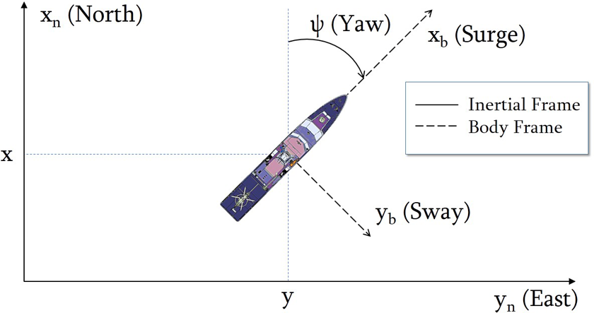
Inertial NED frame and body-fixed frame for a ship with heading angle ψ. NED: north east down.
Dynamics
The motion of a marine vessel classified in six DOFs, defined according to the Society of Naval Architects and Marine Engineers (SNAME) 1 notation (1950), is shown in Table 1. Moreover, its motion can be described by the following vectors38

Notation used for vessels. 38
DOF: degree of freedom.
where η1 and η2 denote the position and orientation vectors, respectively, and η denotes the position and orientation vector defined in the n-frame. Similarly, ν1 and ν2 denote the linear and angular velocities, respectively, and ν denotes the linear and angular velocity vectors according to b-frame. τ1 and τ2 represent the forces and moments, respectively, while τ is used to indicate the forces and moments acting on the vessel in b-frame. To design the SMC scheme for a ship, the following assumption is needed.
Assumption 1
We assume that the ship is stable in the surge and sway directions and they have negligible amplitudes
According to Assumption 1, we can neglect roll, pitch, and heave dynamics. Therefore, the kinematic equations of motion reduce from six DOFs to three DOFs and now the state vectors are
The n-frame velocity vector is related to the b-frame velocity vector with one principal rotation about the z-axis according to the following kinematic relation 7

where R(ψ) is the rotation matrix defined as 7
Rigid-body dynamics
By Newton’s second law of motion, the rigid-body equation of motion can be written as 2

where MRB is the rigid-body system inertia matrix, CRB(ν) is the corresponding centripetal and Coriolis matrix, and τRB is a generalized vector of external forces and moments. For the matrices, MRB and CRB(ν), we give the following assumption.
Assumption 2
Let the ship be port-starboard symmetric (xz-plane symmetry) having homogeneous mass distribution and the center of gravity located at a distance xg along the body x-axis of the b-frame and yg = 0. 2
Considering Assumption 2, MRB can be written as

where m is the mass of the ship and Iz is the moment of inertia about z-axis in the b-frame. The Coriolis–centripetal matrix CRB(ν) can be written skew-symmetrically as

Hydrodynamics
In an ideal fluid, there are several hydrodynamic effects such as added mass, restoring forces, and radiation-induced potential damping. Moreover, there are other damping effects including skin friction, wave drift damping, and vortex shedding. In the current simplified scenario of three DOFs model, the minor effects can be neglected. 6 Considering the major hydrodynamic effects, equation (3) can now be written as 2

where M = MRB + MA, C(ν) = CRB(ν) + CA(ν), and D(ν) = DL + DNL(ν). And we have

where
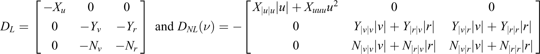
where X(.), Y(.), and N(.) are the hydrodynamic parameters according to the notation of SNAME.
8
For low-speed applications, it is convenient to neglect the nonlinear damping matrix and replace

Model decoupling
The mathematical model discussed in the previous section, represented by equation (4), can be simplified by supposing a constant surge speed u = u0. The sway–yaw dynamics can be separated from the surge model assuming port-starboard symmetry. This sway–yaw model can be written as 2

where


Here, N(u0) can be obtained by the summation of the Coriolis–centripetal matrix CYN(u0) and the linear damping DLYN, that is 2

where

If the ship is controlled by a single rudder, then we obtain

where

where Yδ and Nδ are the coefficients of force in sway and moment in yaw, respectively. 2
The model in equation (6) is linear, and it can be written in the form of Davidson and Schiff. 2,40 Now, this model can be transformed into Nomoto’s model by eliminating the sway velocity written as 2,41
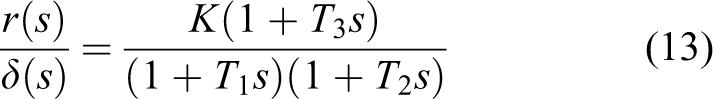
The above transfer function is called Nomoto’s transfer function, and time constants Ti,(i = 1,2,3) and the gain constant K are related to the hydrodynamic coefficients according to the following equations 7


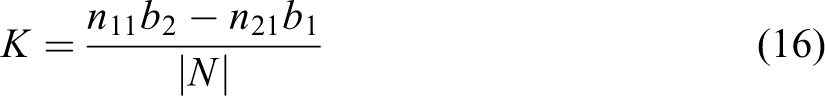

where the coefficients mij, nij, and bi are the components of the matrices M, N, and b in equation (6), and |M| and |N| are the determinants of the matrices M and N, respectively. Here, an assumption is made as follows:
Assumption 3
For the above Nomoto’s model in equation (13), it is assumed that a positive deflection δ will give a positive yaw rate r and vice versa.
According to Assumption 3, the value of K cannot be negative. Experimentally, the time constants T2 and T3 are found to be nearly equal.
42
Hence, the order of equation (13) can be reduced by introducing an effective time constant

From Figure 2, which illustrates the stern of a ship, it can be inferred that


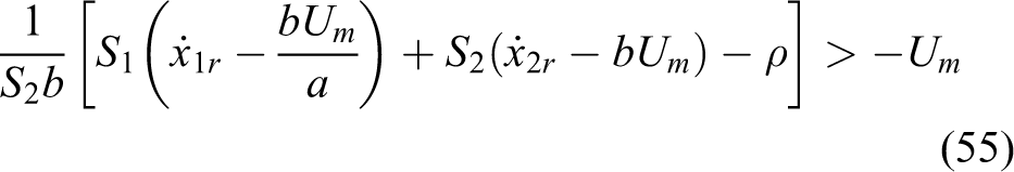
The maximum rudder deflection on both sides.
where rm is named as the maximum yaw rate. By Assumption 3, equation (19) can be split as


Considering Assumption 1, we get

Due to the simplicity and effectiveness of the above model, it is commonly used for steering in autopilot systems. 7,38 Moreover, it can be written in the form of a state equation considering input saturation as 7

where

and

Model of Esso Osaka tanker
The real “Esso Osaka” tanker was scaled down by 1:100 (k = 100) to create a model, which is used for experimentation and verification of various control and guidance systems. The physical model of this ship is present in the Marine Cybernetics Laboratory, Department of Engineering Cybernetics, Norwegian University of Science and Technology, Trondheim, Norway. The main characteristics of this ship are listed in Table 2.
“Esso Osaka” model particulars. 38
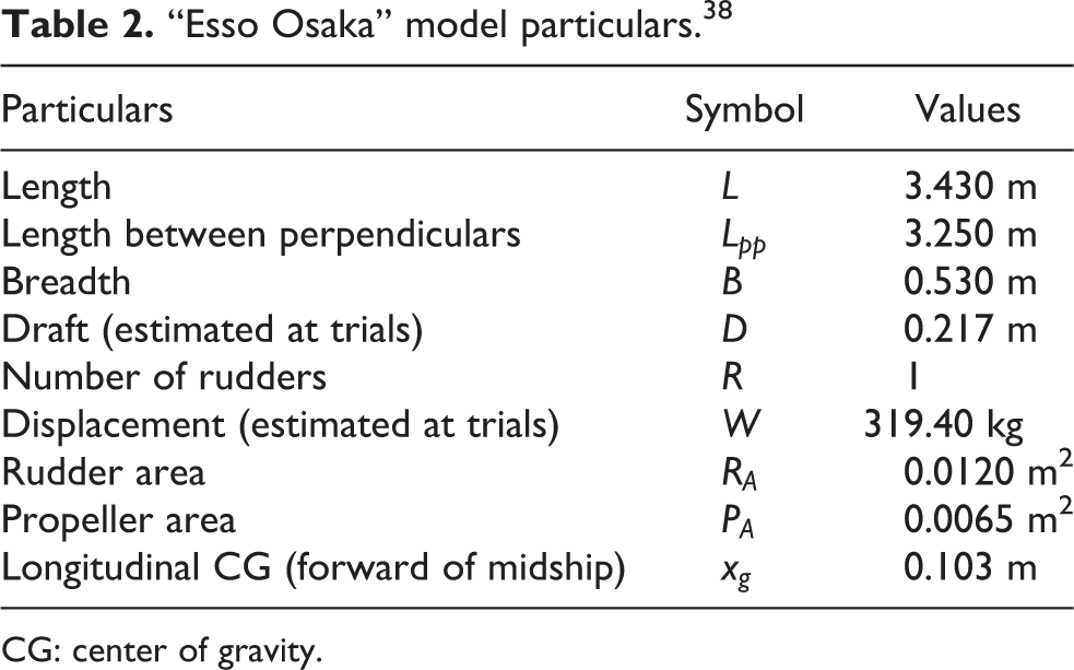
CG: center of gravity.
For this ship moving at a speed of 0.4 m/s, the values of K and T of the equation (18) are calculated as 0.1705 s−1 and 7.1167 s, respectively. 38 After transforming this into equation (23), we can find the values of a and b as −0.1405 and 0.0240, respectively.
Sliding mode control design
Design of sliding mode control with input saturation
Sliding mode controller is a robust controller in which matched uncertainty doesn’t deteriorate the control quality. The structure of the sliding mode controller usually consists of two parts, linear control and nonlinear control. The linear control is called equivalent part, which is designed for linearized system and is responsible to control while the system is on the sliding mode surface. The second part is a switching controller, which is responsible to take the system to the sliding mode surface. While on sliding mode surface, the system becomes insensitive to external disturbances and parametric variations to some extent. 27 Its structure can be represented as

where ueq is the linear part and usw is the non linear part of the controller. To design the controller, the system defined in equation (23) can be written as

where

The sliding mode surface is designed as

where

where S1 > 0 and S2 > 0 are the design constants and should make SB nonsingular. Substituting equation (30) into equation (29) yields

where

where

By taking

The switching control can be designed as

where ρ is to be designed to select the gain of the switching part and it should not be confused with the position and orientation vector described in “Mathematical model of a ship” section. The value of ρ determines how quickly the system will reach the sliding mode surface. 43 Moreover, sgn(.) is the sign function defined as

Then, the sliding mode control scheme can be written as

Invoking the definitions of all variables yields

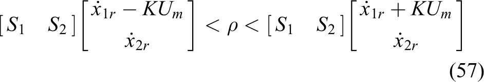
To avoid any nonlinearity or instability, the actuator should not reach saturation limitation. Hence, it should be guaranteed that

or

The rudder deflection on both sides can be treated separately; therefore, the last inequality can be split as


Before substituting the control output in inequalities (41) and (42), we know from equation (38) the value of sign function sgn(.) depends upon σ. Moreover, it should be noted that when sgn(σ) = 0, then the system is in sliding mode and there is no need to evaluate ρ in this case. Thus, there are two possibilities left with respect to sgn(σ) as follows:
Case A: σ < 0, sgn(σ) = −1
By substituting value of u from equation (38) into the last two inequalities (41) and (42) and then substituting


Substituting the respective maximum possible yaw rate from equations (20) and (21) into the last two inequalities yields


From equation (24), the value of K can be found as 7

Considering equations (45), (46), and (47), these can be written as


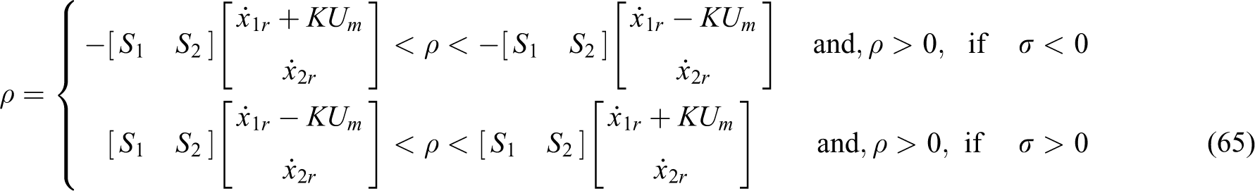
Finally, the value of ρ for this case can be found as

The above inequality can be used to choose the value of η to avoid saturation for
Case B: σ > 0, sgn(σ) = 1
Similarly, by substituting value of u into inequalities (41) and (42) and afterwards substituting rm− and rm+ for x2, we obtain


and substituting the respective maximum possible yaw rate from equations (20) and (21) to the above inequalities yields


Considering equations (53), (54), and (47), these can be written as

Similarly, for this case, the value of ρ can be found as
The above inequality can be used to choose the value of ρ to avoid saturation for sgn(σ) = 1.
In the proposed algorithm, the values of K, S1, S2, ρ, and Um are positive. If σ is positive, then case A should be satisfied, and if σ is negative, then case B should be satisfied. Based upon the above analysis, the following theorem can be summarized.
Theorem 1
A steering system of a ship is considered with input saturation. All states are available and the sliding mode control scheme is designed as equation (38). Then, all signals of the close-loop system are convergent, if the value of ρ is positive and satisfies (65).
Proof
According to Lyapunov stability theorem, the origin of a system is asymptotically stable, if there is a positive definite function V, such that

By substituting values from equation (29), we have

It can be stated that the above function is positive. Taking derivative yields

Now substituting the value of

Substituting the value of u from equation (38) gives

From the definition of signum (or sign) function, we know that |σ| = sgn(σ)σ. Thus, equation (62) can be written as

The value of the last equation will be negative, only if ρ is positive, that is

which is the condition for the stability of the system and the proof is concluded. A criteria for selection of η can be written in a nutshell as
Remark 1
To maintain any fixed value of the output of the ship using control techniques is called set point regulation. In this case, the direction of the ship (i.e. ψ) can be regulated by keeping

or

Equation (67) and Theorem 1 can be used for the criteria of set point regulation in the presence of saturation.
Chattering avoidance
A drawback for SMC system is chattering. Chattering is a phenomena of high-frequency oscillations having finite magnitude of the output of the SMC system while operating in the sliding mode surface. In many practical applications, it becomes important to avoid chattering because it can lead to high wear and tear, high temperature, and unwanted excitation of the actuators. 23 For instance, a vessel’s hydrodynamic surfaces are not capable of moving with high frequency, but the control system should be effective and in synchronization. 45
One method to suppress chattering is using sat(.) (saturation) function instead of the discontinuous sgn(.) function, which can be defined as

where l is any positive number which represents the level of saturation.
However, a better method to suppress chattering is to use fuzzy logic to handle the gain ρ in equation (38). In spite of improving the system performance, using fuzzy SMC, the robustness of the system is also guaranteed. 46 Therefore, the input and output membership functions are designed as shown in Figures 3 and 4, respectively. The rule base of the fuzzy system is designed as 46 –48
If σ is N, then ρ is P
If σ is Z, then ρ is Z
If σ is P, then ρ is P

The membership function of fuzzy input σ.

The membership function of fuzzy output ρ.
where N, Z, and P are the fuzzy terms which can be seen from Figures 3 and 4 for fuzzy antecedent and consequent, respectively.
The flowchart for the complete design of the proposed control system is given in Figure 5.
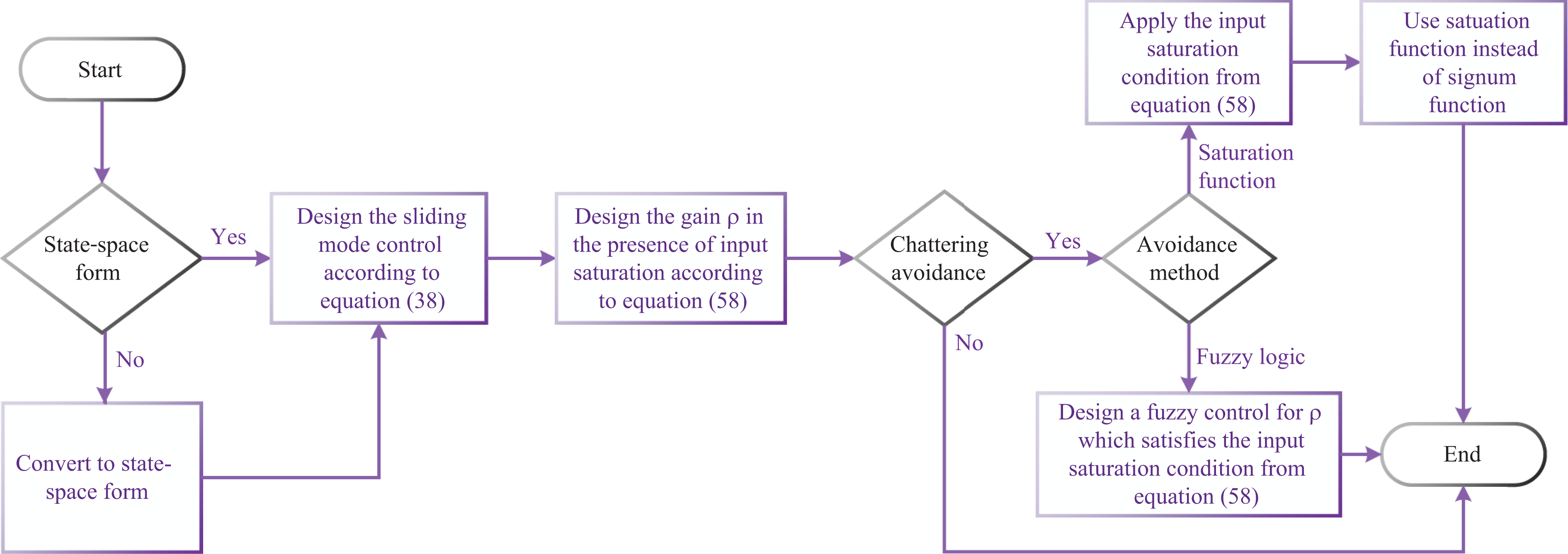
Flowchart of the proposed control system (ψ).
Simulation results
A reduced scale model ship of a tanker named Esso Osaka is simulated assuming calm water with infinite depth. This simulation is performed at the scale of the model ship. It was assumed to move with a constant speed of 0.4 m/s, initially, toward the true north (i.e. x-axis). As assumed in the study by Perera and Soares, 23 the saturation limit of the rudder is considered as π/4 radians on both sides. The value of l in equation (68) is selected as 1.
The initial conditions can be written as

Set point regulation
For simulation purpose, a scenario is created, which has an objective that the ship has to turn an angle of 180° (x1r = π rad) and regulate this heading (x2r = 0). To avoid saturation, equation (67) must be satisfied.
Let us suppose the value of S1 = 1 and S2 = 6, therefore

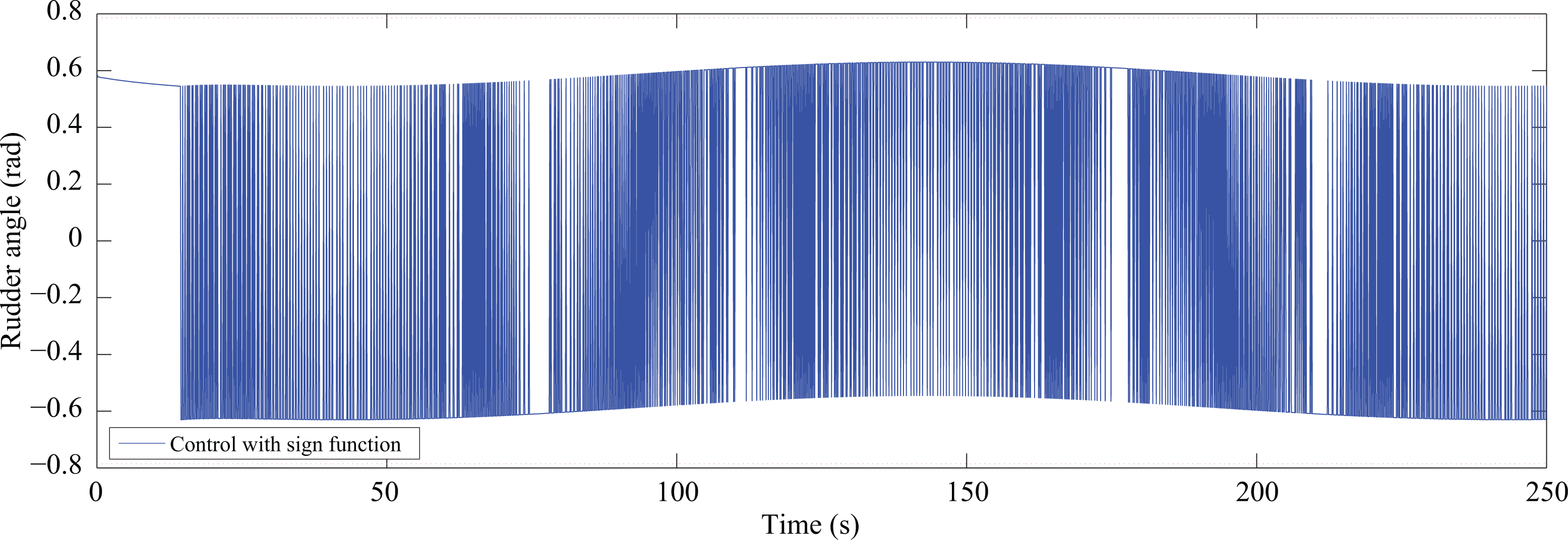
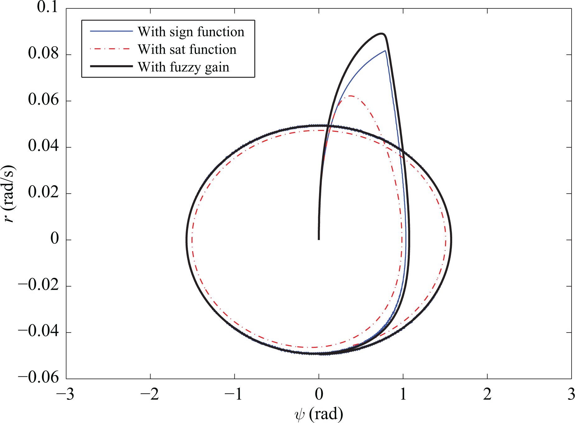
By fulfilling the above condition, it is ensured that the system will not go in saturation mode. Let the value of ηρ be 0.1, which fulfills the above condition. Figure 6 shows the transient response of the system. In this figure, it can be seen that using fuzzy gain for chattering avoidance doesn’t deteriorate the results much as compared to using saturation function. The output of the control system, that is, rudder angle, is shown in Figure 7 with sgn(.) function, in which chattering effect can be observed. The output using fuzzy gain and sat(.) functions is shown in Figure 8. The evidence of the sliding mode is shown in Figure 9, in which the sliding surface can be seen for sgn(.) function and fuzzy gain only. The path followed by the ship can be seen from Figure 10, in which it can be seen that it has successfully turned an angle of 180°; however, using the saturation function, the turning radius has increased. Hence, these results conclude that using the traditional sgn(.) function produces chattering effect, which makes the system less efficient. Although the sat(.) function eliminates the chattering, it slows the system and increases the turning radius. Therefore, in this scenario, the proposed method using fuzzy gain is more efficient as compared.
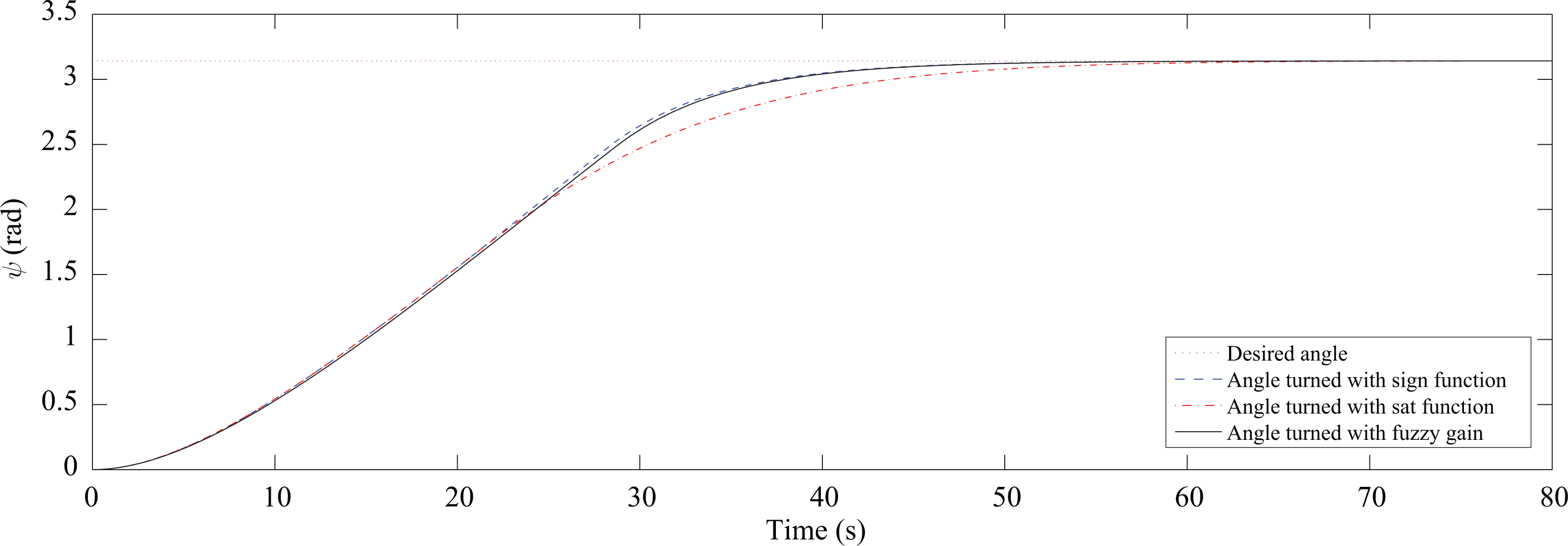
Angle turned by the ship (ψ).

Control output (rudder angle δ).

Control output (rudder angle δ).

ψ-ψ′ plot showing the sliding surface.

Path followed by the ship.
Reference tracking
To further test the control system, we can create a different scenario with the same initial conditions. This time, the ship has to track a cosine wave of frequency equal to π/100 = 0.0314 rad/s. It can be seen from Figure 11 that initially, the control system attempts to reach the desired angle and after reaching it, it maintains this time-varying signal except for saturation function, in which a delay is also observed. Figures 12 and 13 show the control signals, while Figures 14 and 15 show the ψ − ψ′ plot and path followed by the ship, respectively, for this scenario. From these results, we see that although the saturation function eliminates the chattering effect, it produces a delay. This delay makes the control system less efficient, while fuzzy SMC removes the effect of chattering with negligible effect on the system performance.

Angle turned by the ship (ψ).
Control output (rudder angle δ).

Control output (rudder angle δ).
ψ-ψ′ plot showing the sliding surface.

Path followed by the ship.
Conclusion
In this article, SMC has been proposed for the steering control of saturated surface vessels. The autopilot system designed for the mathematical model of the scaled replica of Esso Osaka tanker is simulated in MATLAB to demonstrate the performance of the system. Set point regulation and input tracking are simulated for this scenario. The results show that this controller is effective and stable for saturated actuators and can be readily applied to other vessels. Furthermore, the simulations show that using fuzzy gain for the SMC is much better for chattering avoidance than using saturation function.
Footnotes
Declaration of conflicting interests
The author(s) declared no potential conflicts of interest with respect to the research, authorship, and/or publication of this article.
Funding
The author(s) disclosed receipt of the following financial support for the research, authorship, and/or publication of this article: This work was supported in part by the Fundamental Research Funds for the Central Universities under Grant NE2016101.