
Abstract
A novel fault-tolerant communication topology management method for the leader–follower unmanned aerial vehicle (UAV) formation is proposed to minimize the formation communication cost while keeping the formation shape, even in the case of communication faults during the formation flight. This method is based on Edmonds’ algorithm for the minimum cost arborescence problem in graph theory. When a formation shape is given before the formation flight, this method can get the optimal initial communication topology with the minimum formation communication cost for keeping the formation shape. When some communication faults occur during the formation flight, which will cause the formation shape cannot be kept, this method can reconfigure the communication topology in time to guarantee the safety of all UAVs and recover the formation shape, and then it can reoptimize the communication topology by UAV position reconfiguration in the formation shape to minimize the formation communication cost for continuously keeping the formation shape. The effectiveness of this method is demonstrated through several simulation experiments.
Keywords
Introduction
The cooperative decision and control of multiple unmanned aerial vehicles (UAVs) have drawn considerable attention from the scientific and engineering communities in recent years due to their wide potential applications in many fields, such as joint search and track, 1 persistent surveillance, 2 localization and navigation, 3 environmental monitoring, 4 ground target attack, 5 and so on. In order to get a better task performance, multiple UAVs usually need to form and keep a certain formation shape (geometric configuration) by information exchange through partial communication links among them, 6 where the set of communication links being used is called the communication topology, 7,8 information exchange topology, 9 or connection topology 10 of the UAV formation. Due to different communication distances and other reasons, communication links in the communication topology usually have different communication costs, that is, they will consume a different amount of battery power or fuel. 11 –13 Meanwhile, the available battery power or fuel of each UAV is usually limited. Furthermore, some communication faults may occur during the formation flight, which will cause that some communication links in the communication topology become unusable and the formation shape cannot be kept. Therefore, an efficient fault-tolerant communication topology management method is beneficial and necessary for a UAV formation to minimize the total cost of the communication links in the communication topology (called the “formation communication cost”) while keeping the formation shape even when some communication faults occur during the formation flight.
To form and keep a formation shape, UAVs usually use one of the following four main formation control approaches: leader–follower-based approach, 14 –18 virtual structure-based approach, 19 –21 behavior-based approach, 22 –24 and consensus-based approach. 25 –28 Different communication topologies are needed for these different formation control approaches. For example, the communication topology for leader–follower-based approach is a (directed) spanning tree, the communication topology for virtual structure-based approach and behavior-based approach is a bidirectional ring, and the communication topology for consensus-based approach must have a subset that is a (directed) spanning tree. 9 This article focuses on the research of fault-tolerant communication topology management under communication faults for the leader–follower UAV formation, where all UAVs use the leader–follower-based approach to form and keep the formation shape. In this formation, only one UAV (referred to as the formation leader) will track the predefined formation reference trajectory. Other UAVs (referred to as the following UAVs) will directly or indirectly follow the formation leader. For example, one UAV may directly follow the formation leader or follow another UAV that may directly or indirectly follow the formation leader. To the best of our knowledge, only a few results have been reported about the fault-tolerant communication topology management under communication faults for the leader–follower UAV formation.
In the studies of Giulietti et al. and Pollini et al., all available communication links in a leader–follower UAV formation with n UAVs are described by a weighted directed graph. First, an algorithm with a computation complexity of O(n2) based on Dijkstra’s algorithm for the shortest path problem in graph theory is proposed to get the optimal initial communication topology for a given formation shape before the formation flight, where each following UAV has a shortest communication path from the formation leader. This path is composed of one or more communication links. However, the whole communication path for all the following UAVs may not be the shortest, which means that the formation communication cost may not be minimal. Second, when some communication faults occur during the formation flight, an alternative broadcast communication channel (BC) is used to inform all UAVs of these communication faults, and then each UAV runs Dijkstra’s algorithm again to get a suboptimal reconfigured communication topology to guarantee the safety of all UAVs and recover the formation shape. This method can deal with four types of communication faults, including transmitter failure, receiver failure, transceiver failure (UAV loss), and link interrupt (link loss), but other possible types of communication faults, including BC transmitter failure and BC receiver failure, have not been taken into account. Third, after the communication topology reconfiguration following some communication faults, a UAV position reconfiguration in the formation shape is performed based on some predefined reconfiguration maps (RMs) and heuristic laws to reoptimize the communication topology. However, the design of RMs lacks adequate theoretical basis and only adapts to some fixed formation shapes.
In Yang et al.’s study, all available communication links in a leader–follower UAV formation with n UAVs are also described by a weighted directed graph. First, an algorithm with a computation complexity of
Therefore, to overcome the shortcomings in the existing research literatures, this article proposes a novel fault-tolerant communication topology management method under communication faults for the leader–follower UAV formation, which is based on Edmonds’ algorithm for the minimum cost arborescence (MCA) problem in graph theory. The main contributions of our method can be summarized as follows:
Initial communication topology optimization: A novel initial communication topology optimization algorithm is proposed, which has a lower computation complexity and can get a better initial communication topology, where each UAV is assigned the most suitable position in the formation shape, and the most suitable UAV is selected to be the formation leader.
Communication topology reconfiguration under communication faults: A novel communication topology reconfiguration algorithm is proposed, which has a lower computation complexity, can deal with more types of communication faults, and can get a better reconfigured communication topology.
Communication topology reoptimization under communication faults: A novel communication topology reoptimization algorithm is proposed, which can get a better reoptimized communication topology, where each UAV is assigned the most suitable new position in the formation shape.
The remainder of this article is organized as follows. In section 2, the related background and preliminaries are provided. In section 3, the proposed method is presented in detail. In section 4, the effectiveness of the proposed method is validated by simulation results. In section 5, concluding remarks are offered.
Background and preliminaries
Formation controller of each UAV in the leader–follower UAV formation
Let UAV i and UAV j denote the ith and the jth UAV in the leader–follower UAV formation. If UAV i directly follows UAV j during flight, UAV i is called the follower of UAV j and UAV j is called the leader of UAV i . UAV j will send its own position, speed, and direction information to UAV i through a point-to-point communication link every Tcontrol seconds. When UAV i receives this information, it will use a formation controller to adjust its speed and direction to keep a desired relative position from UAV j . In this article, we assume that each UAV has a formation controller as proposed in the studies of Yang et al. and Xu et al., 29 which is described as follows.
First, assume that all UAVs fly at the same height, and then the kinematic model of UAV i can be simplified as
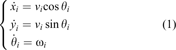
where (xi , yi ) denotes the position of UAV i , vi denotes the speed of UAV i , θi denotes the heading angle of UAV i , and ωi denotes the angular velocity of UAV i .
Second, assume that the leader of UAV
i
is UAV
j
, and then the formation error of UAV
i
can be denoted by the forward error


where fij
and lij
denote the actual forward and lateral distances between UAV
i
and UAV
j
, respectively, as shown in Figure 1,
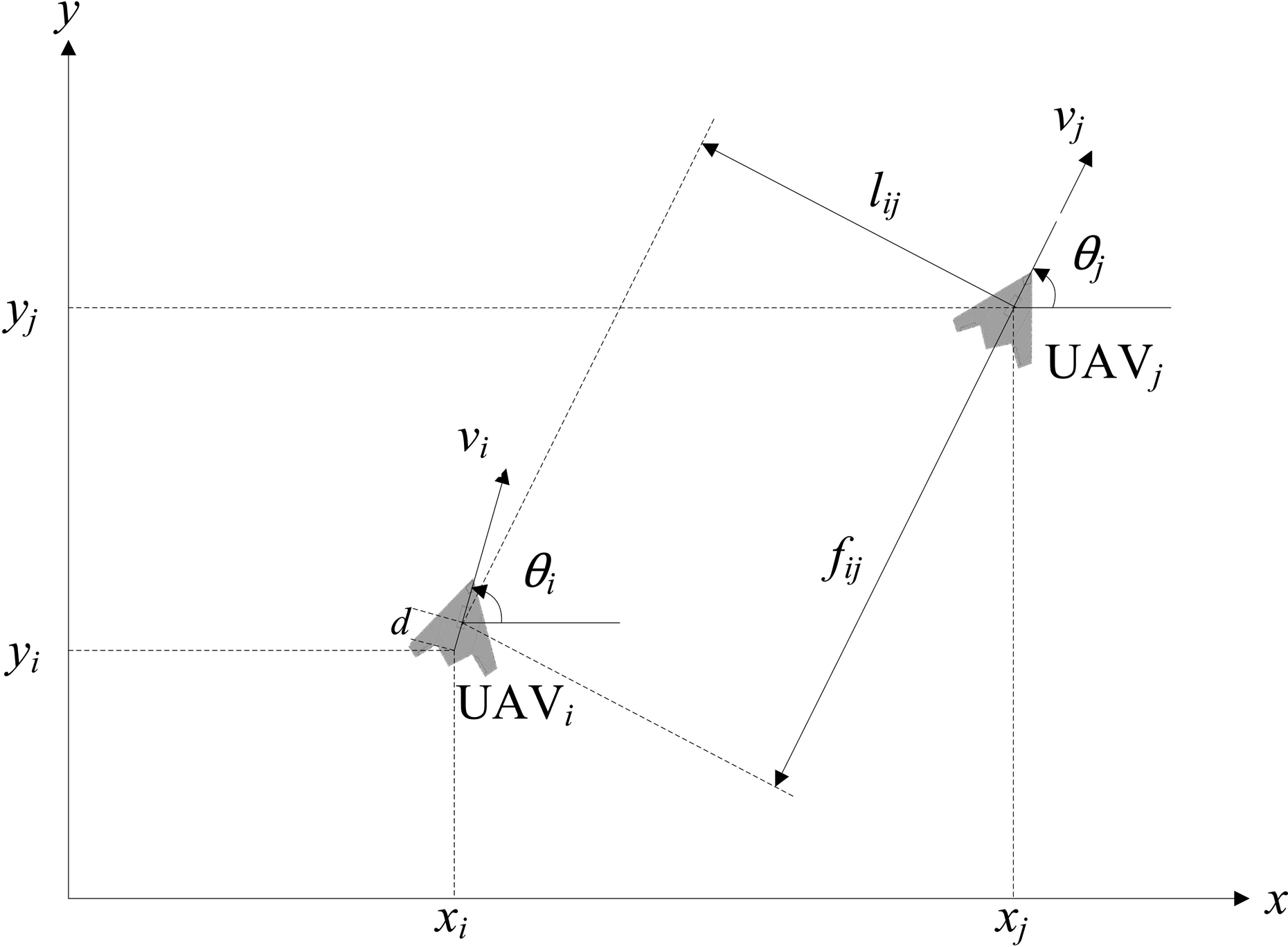
The actual forward and lateral distances between UAV i and UAV j . UAV: unmanned aerial vehicle.
Finally, based on the above assumptions and descriptions, the formation controller of UAV i can be designed as

where
Communication topology of the leader–follower UAV formation
Assume that n UAVs use the leader–follower formation controller described above to form and keep a given formation shape S with n positions that are at the same height h0 and are numbered by
In the leader–follower UAV formation, each UAV only needs to receive information from its leader and send information to its followers, which means that not all available communication links must be used at all times for forming and keeping the formation shape. Therefore, the set of communication links being used in a leader–follower UAV formation is called its communication topology, 7,8 which is a special subgraph of its communication link graph and has the following feature:
Theorem 1
The communication topology of a leader–follower UAV formation must be a spanning tree of its communication link graph, but a spanning tree of its communication link graph is not necessarily a communication topology of the leader–follower UAV formation.
Proof
In a leader–follower UAV formation, except for the formation leader, each UAV must directly or indirectly follow the formation leader. Namely, the formation leader must have a unidirectional communication path, composed of one or more communication links, to each following UAV. Therefore, all communication links being used in the formation will form a spanning tree of its communication link graph, and the root node of this spanning tree denotes a UAV that can be the formation leader. However, not all UAVs can be the formation leader. Therefore, given a spanning tree of the communication link graph, if its root node denotes a UAV that cannot be the formation leader, then this spanning tree cannot be a communication topology of the leader–follower UAV formation. Based on the above analysis, we can naturally conclude theorem 2.
Theorem 2
The communication topology of a leader–follower UAV formation must be a spanning tree of its communication link graph whose root node denotes a UAV that can be the formation leader, and vice versa.
Fault-tolerant communication topology management based on MCA
As we can see from theorems 1 and 2, the communication link graph of a leader–follower UAV formation may have multiple spanning trees that can be a communication topology of this formation, and these spanning trees may have different communication costs because they are composed of different communication links. Therefore, we can select the optimal one from these spanning trees to be the initial communication topology before the formation flight to minimize the formation communication cost. Meanwhile, except for the communication links being used in the communication topology, the other communication links are not used (these are referred to as redundant communication links). Therefore, we can also use the redundant communication links to deal with the communication faults during the formation flight by using them to replace the faulty communication links. Based on the above analysis, this article proposes a novel fault-tolerant communication topology management method under communication faults for the leader–follower UAV formation (based on Edmonds’ algorithm for the MCA problem in graph theory), and it is presented as follows.
Initial communication topology optimization before the formation flight
Before the formation flight, all UAVs need to get an initial communication topology for forming and keeping a given formation shape based on the following assumptions: Each UAV can occupy any position in the formation shape. Several UAVs, but not all UAVs, can be the formation leader. Each UAV can communication with all other UAVs through different point-to-point communication links. The communication cost of a communication link is evaluated by its communication distance.
Under these assumptions and the above description of the communication topology, the objective of the initial communication topology optimization problem before the formation flight is to determine the optimal spanning tree of the corresponding communication link graph
When using Edmonds’ algorithm to solve this problem, the first step is to construct the communication link graph
After determining
G
, we can calculate its MCA denoted by

According to the properties of MCA, if A exists, then A has n nodes and n − 1 arcs, and the total weight of its arcs is minimal. However, A cannot be a communication topology if its root node vi denotes a UAV that cannot be the formation leader. Fortunately, all UAVs are almost exactly the same before the formation flight, except that part of UAVs cannot be the formation leader. Therefore, in this case, we just need to find another node vj denoting a UAV that can be the formation leader, and then exchange the position of vi and vj in G and A to make A become a communication topology. Moreover, this position exchange does not change the total weight of all arcs in A, so A must be the optimal initial communication topology.
Based on the above analysis, this article proposes an initial communication topology optimization algorithm based on MCA, which is shown in Table 1.
Algorithm 1: Initial communication topology optimization.

UAV: unmanned aerial vehicle; MAC: minimum cost arborescence.
The computation complexity of algorithm 1 mainly depends on the computation complexity of step 2, in which the faster implementation of Edmonds’ algorithm in the study of Gabow et al. is used.
31
Therefore, the computation complexity of algorithm 1 is It has a lower computation complexity than the algorithm with a computation complexity of It does not need to artificially specify the position of each UAV in the formation shape, and can automatically select the most appropriate position for each UAV. It does not need to artificially specify the formation leader, and can automatically select the most appropriate UAV to be the formation leader.
Algorithm 1 can be used in a centralized scheme or a decentralized scheme. In the former case, the ground control center runs algorithm 1 and informs all UAVs of the result. In the latter case, each UAV runs algorithm 1 and also gets the same result. Once knowing the optimal initial communication topology, the formation leader begins to track the predefined formation reference trajectory and other UAVs begin to follow its leader. Soon all UAVs form the corresponding formation shape, and then will keep the formation shape.
Communication topology reconfiguration under communication faults
During the formation flight, if some communication faults occur in one or more UAVs, UAVs may not continue to keep the formation shape, and may even collide with one another. Therefore, all UAVs should reconfigure the communication topology quickly to avoid the UAV collision and recover the formation shape. At the same time, in order to reduce the cost of communication, the communication cost of the reconfigured communication topology should be as small as possible.
The communication topology reconfiguration must be decentralized for faster execution time, and the reconfiguration algorithm must get the same result in all UAVs (i.e. all UAVs must be informed of the same communication fault information in time). To this end, this article assumes that each UAV can use a broadcast communication channel (BC) to get the same communication fault information as in the studies of Giulietti et al., Pollini et al., and Yang et al.: Each UAV has a unicast transmitter and a unicast receiver for point-to-point communication, and a broadcast transmitter and a broadcast receiver for broadcast communication through the BC. Each UAV will report its status through the BC every T active seconds. When a UAV detects a communication fault, it will immediately notify all other UAVs through the BC.
Beside the four types of communication faults considered in the studies of Giulietti et al., and Pollini et al., and Yang et al., this article also deals with two additional types of communication faults: broadcast transmitter failure and broadcast receiver failure. All six types of communication faults are listed in Table 2.
Different types of communication faults.

UAV: unmanned aerial vehicle.
For the six types of communication faults, we assume that all UAVs have the same fault detection and isolation (FDI) strategy as follows: When a unicast transmitter failure, a unicast receiver failure, a unicast transceiver failure, or a broadcast receiver failure occurs in UAV
i
, UAV
i
itself can detect this fault. Then, UAV
i
will record the time stamp of this fault and notify other UAVs of this information through the BC. When a broadcast transmitter failure occurs in UAV
i
, UAV
i
itself can detect this fault, but cannot notify other UAVs through the BC. Because other UAVs will never receive the status of UAV
i
, after Tactive seconds they can conclude that UAV
i
has encountered a broadcast transmitter failure and will record the time stamp of this fault. When a link interrupt occurs in the communication link eij and UAV
i
is the leader of UAV
j
, UAV
j
cannot receive the position, speed, and direction information from UAV
i
again. After Tactive seconds, if UAV
j
does not detect its own unicast receiver failure, and does not receive the unicast transmitter failure information of UAV
i
, UAV
j
will conclude that eij is interrupted. Then, UAV
j
will record the time stamp of this fault and notify other UAVs of this information through the BC. When a UAV receives information about a communication, it processes the communication fault immediately, which includes first updating the communication link graph according to the communication fault information and then optimizing the communication topology. If information about a new communication fault is received during the process flow, the UAV interrupts the current process flow immediately, and then processes the new and old communication faults together, which includes first updating the communication link graph according to the new communication fault information and then optimizing the communication topology again.
Based on the above FDI strategy, each UAV will quickly receive the same communication fault information if some communication faults occur, and then can get the reconfigured communication link graph If a unicast transmitter failure occurs in UAV
j
, delete all the outgoing arcs of vj. If a unicast receiver failure occurs in UAV
j
, delete all the incoming arcs of vj. If a unicast transceiver failure or a broadcast transmitter failure or a broadcast receiver failure occurs in UAV
j
, delete all the arcs of vj. If a link interrupt occurs in the communication link from UAV
j
to UAV
k
, delete ejk. If all the arcs of vj are deleted, then delete vj and let
Then, each UAV should get the optimal spanning tree of Gr to be the optimal reconfigured communication topology, which has the minimal communication cost and roots at a node denoting a UAV that can be the formation leader. Therefore, this problem can also be modeled as the MCA problem in graph theory. When using Edmonds’ algorithm to get the MCA of Gr (which is denoted by Ar), the results can be divided into two kinds as follows: The root node vi of Ar denotes a UAV that can be the formation leader, and then Ar can be the optimal reconfigured communication topology (i.e. each UAV can reconfigure its communication topology into Ar to recover the formation shape). The root node vi of Ar denotes a UAV that cannot be the formation leader, and then Ar cannot be a reconfigured communication topology (i.e. each UAV cannot reconfigure its communication topology into Ar to recover the formation shape). However, this doesn’t mean that there must be no other reconfigured communication topologies.
Therefore, in order to find the optimal reconfigured communication topology in the above two cases, this article proposes a new method based on MCA. First, a special node called virtual leader (VL) and its corresponding outgoing arcs are added into
Second, the MCA of
Theorem 3
If the MCA of G′ r denoted by A′ r exists and v0 has only one outgoing arc in A′ r , then the optimal reconfigured communication topology Ar exists and it can be achieved by deleting v0 and its outgoing arcs from A′ r .
Proof
First, if A′
r
exists, A′
r
must be a spanning tree of G′
r
, which means that A′
r
must contain all nodes in G′
r
, and each node in A′
r
must have an incoming arc except for the root node. Moreover, v0 does not have any incoming arc based on the definition of G′
r
, so v0 must be the root node of A′
r
and have at least an outgoing arc. Second, because G′
r
has
Based on the above analysis, this article proposes a decentralized communication topology reconfiguration algorithm under communication faults based on MCA, which is executed in each UAV when a communication fault occurs. Taking UAV i as an example, if it receives a communication fault notification from other UAV through the BC or detects its own communication fault, it will run the algorithm as shown in Table 3.
Algorithm 2: Communication topology reconfiguration under communication faults.

UAV: unmanned aerial vehicle; MAC: minimum cost arborescence.
After running algorithm 2, all remaining UAVs in the formation switch to the optimal reconfigured communication topology to quickly recover the formation shape. The computation complexity of algorithm 2 mainly depends on the computation complexity of step 7 in which the faster implementation of Edmonds’ algorithm in the study of Gabow et al.is used. Therefore, the computation complexity of algorithm 2 is It has a lower computation complexity than the algorithm with a computation complexity of It can achieve a better reconfigured communication topology, which has less formation communication cost. It can deal with more types of communication faults.
Communication topology reoptimization under communication faults
After the communication topology reconfiguration following some communication faults, all UAVs are kept safe, some UAV may leave the formation to track the predefined formation reference trajectory alone at a different height or fly back to its own UAV base alone, and the remaining UAVs will continue keeping the formation shape. However, the formation communication cost may not be optimal (minimal). It may be necessary to reoptimize the communication topology by a UAV position reconfiguration in the formation shape, which includes exchanging UAV positions in the formation shape or moving a UAV to fill an empty position in the formation shape left by a UAV that has left the formation.
Because there are many possible UAV position reconfigurations and under each UAV position reconfiguration, there are also many possible communication topologies, the objective of the communication topology reoptimization problem under communication faults is to determine the optimal UAV position configuration, under which the communication topology with the minimal formation communication cost exists. Therefore, this problem can also be modeled as the MCA problem in graph theory. First, for each possible UAV position configuration Pn, we can construct its corresponding extended communication link graph G′ n . Then, we can use Edmonds’ algorithm to calculate the MCA of G′ n to get a candidate optimal communication topology An for Pn. Finally, all candidate optimal communication topologies for each UAV position configuration are compared to find the reoptimized communication topology Ao with the minimal formation communication cost and its corresponding reoptimized UAV position configuration Po.
Based on the above analysis, this article proposes a decentralized communication topology reoptimization algorithm based on MCA, which is executed in each remaining UAV in the formation. Taking UAV i as an example, the steps of this algorithm are shown in Table 4.
Algorithm 3: Communication topology reoptimization under communication faults.

UAV: unmanned aerial vehicle; MAC: minimum cost arborescence.
In step 5 of algorithm 3, each possible UAV position configuration Pn must be a permutation by taking out |Vr| elements from |V| different elements, which are, respectively,
After running algorithm 3, all remaining UAVs will switch to the reoptimized communication topology and continue keeping the formation shape. The core step of algorithm 3 is step 7, where the faster implementation of Edmonds’ algorithm in Gabow et al.’s study is used. As can be seen from step 4, step 7 will be run no more than
Compared to the communication topology reoptimization algorithm in the studies of Giulietti et al. and Pollini et al., algorithm 3 has the following advantages: It has adequate theoretical basis to ensure that it can achieve the optimal communication topology by UAV position reconfiguration after communication faults. It is more flexible, because it can adapt to any formation shape.
Simulation results and analysis
Two simulations are carried out in MATLAB to demonstrate the efficiency of our proposed fault-tolerant communication topology management method under communication faults for the leader–follower UAV formation. The first simulation demonstrates the efficiency of algorithm 1 for the initial communication topology optimization before the formation flight, and the second simulation demonstrates the efficiency of algorithms 2 and 3 for the communication topology reconfiguration and reoptimization under different types of communication faults during the formation flight.
Assume that five UAVs need to form and keep a wedge formation shape as shown in Figure 2, where all positions, denoted by

Given formation shape before the formation flight.
In addition, only UAV1, UAV2, and UAV4 can be used as the formation leader. The predefined formation reference trajectory is a one-fourth arc from
Initial coordinates and heading angle of each UAV.

UAV: unmanned aerial vehicle.
Initial communication topology optimization before the formation flight
Using the above experiment parameters as input, each UAV runs algorithm 1 to calculate the optimal initial communication topology as follows: In step 1, the initial value of UAV position configuration P is set to
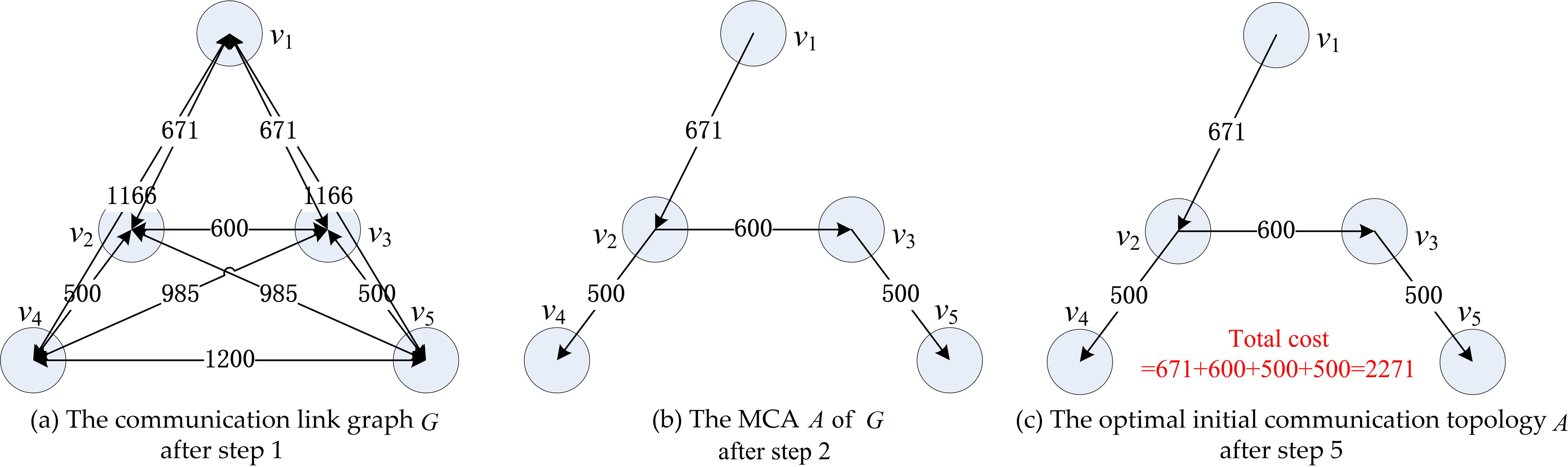
Main calculation process of algorithm 1.
Comparatively, the method in the studies of Giulietti et al. and Pollini et al. can get an optimal initial communication topology with a larger total cost (3674) as shown in Figure 4(a), and its computation complexity is higher than algorithm 1. The method in the study of Yang et al. can get the same optimal initial communication topology as algorithm 1, which is shown in Figure 4(b), but its computation complexity is higher than that of algorithm 1.

Comparison of initial communication topology optimization results.
After getting the optimal initial communication topology, each UAV will use its formation controller described in equation (4) to form and keep the formation shape. Assume that no communication faults occur throughout the formation flight. Figure 5 shows the tracks of all UAVs on the horizontal plane throughout the formation flight, the positions of UAVs at t = 1 s, t = 40 s, t = 80 s and t = 128 s are marked. From this, we can see that the formation shape is formed quickly and then kept until the end.

Tracks of UAVs on the horizontal plane without communication faults. UAV: unmanned aerial vehicle.
Communication topology reconfiguration and reoptimization under communication faults
To demonstrate the efficiency of our proposed method under different types of communication faults listed in Table 2, we designed six different communication fault scenarios (shown in Table 6), and then carried out the contrast experiments for these scenarios to compare our method with the methods in the studies of Giulietti et al., Pollini et al., and Yang et al., respectively. In the six scenarios, the unicast transmitter failure is divided into scenarios 2 and 3 because the method described in the study of Yang et al. does not consider the unicast transmitter failure of the formation leader. Also, the broadcast transmitter failure and the broadcast receiver failure are merged into scenario 6 because our method treats them in the same way.
Six different communication fault scenarios.

UAV: unmanned aerial vehicle.
Next, we take scenario 2 as an example to illustrate the main calculation process of algorithms 2 and 3. When the unicast transmitter failure occurs in UAV2, UAV2 itself can detect this fault and will notify other UAVs of this information through the BC. After receiving this information, each UAV must quickly reconfigure the formation topology to ensure the safety of all UAVs. Therefore, without exchanging the UAV positions in the formation shape, each UAV runs algorithm 2 to calculate the reconfigured communication topology as follows: In step 1, the reconfigured communication link graph Gr and the optimal reconfigured communication topology Ar are initialized. In step 2, the faulty arcs in Gr and in the current communication topology A are deleted according to this communication fault, and the modified Gr and the modified A are shown in Figure 6(a) and (b), respectively. In step 3, because e23 and e24 are deleted by step 2, the remaining operations of step 3 are not executed. In steps 4 and 5, because v2 is not deleted by step 2, the remaining operations of steps 4 and 5 are also not executed. In step 6, the extended reconfigured communication link graph G′ r is established and shown in Figure 6(c). In step 7, the MCA A′ r of G′ r is calculated and shown in Figure 6(d). In step 8, because v0 has only an outgoing arc e01 in A′ r , the optimal reconfigured communication topology Ar is obtained by deleting v0 and e01 from A′ r , and Ar is shown in Figure 6(e).
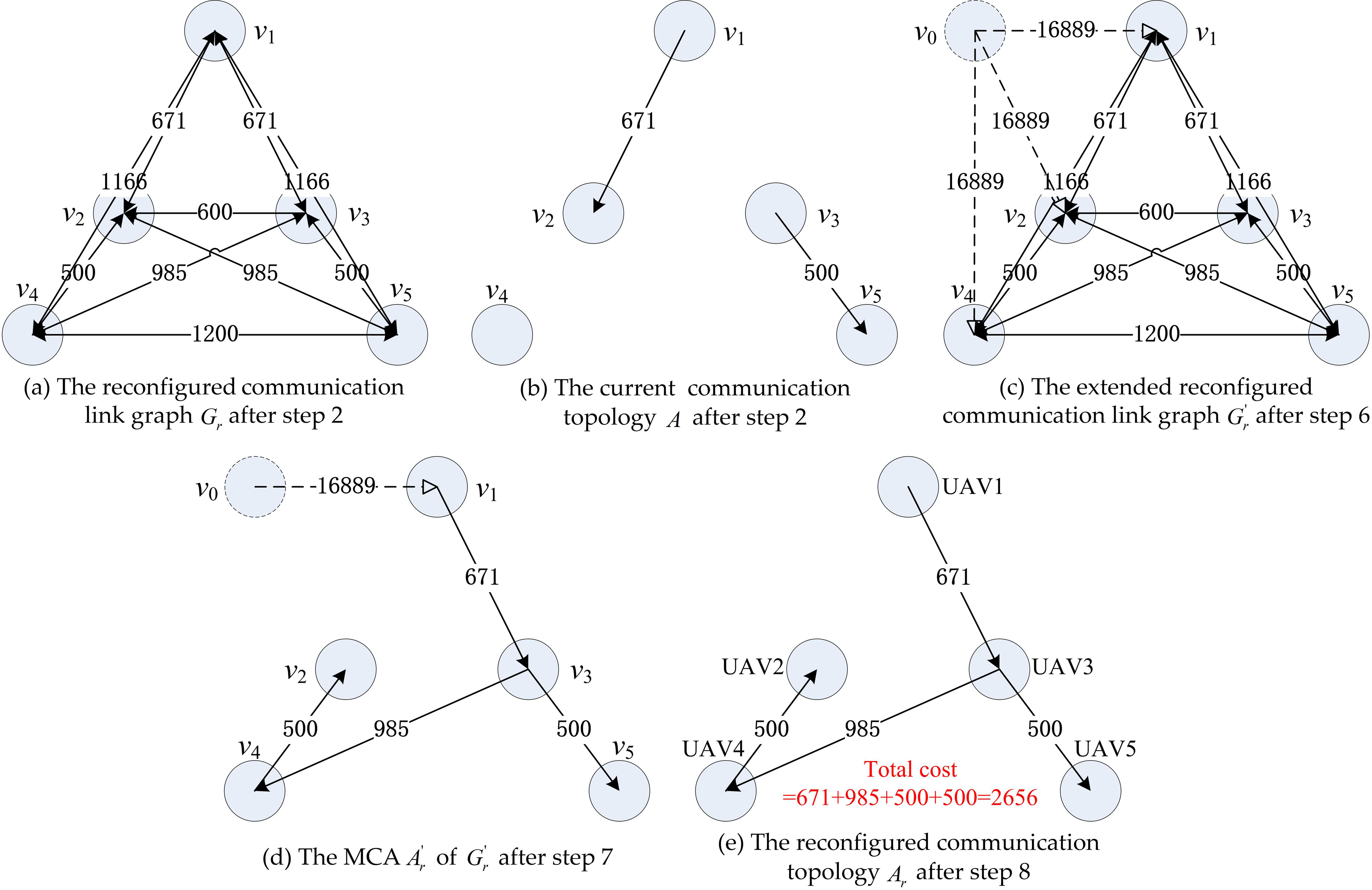
Main calculation process of algorithm 2 in scenario 2.
After the communication topology reconfiguration described above, all UAVs are kept safe and each UAV can reoptimize the communication topology by the UAV position reconfiguration in the formation shape. Therefore, each UAV runs algorithm 3 to calculate the reoptimized communication topology as follows: In step 1, the reoptimized communication topology Ao is initialized as the reconfigured communication topology Ar. In step 2, because no UAV leaves the formation, go to step 3. In step 3, because

Main calculation process of algorithm 3 in scenario 2.
The results of six contrast experiments are listed in Table 7. From which we can reach the following conclusions: Our method can handle more types of communication faults than the methods in the studies of Giulietti et al., Pollini et al., and Yang et al., whereas the method in Yang et al.’s study can only handle the link interrupt as in scenario 1 and the unicast transmitter failure of following UAV as in scenario 2, and the method in the studies of Giulietti et al. and Pollini et al. cannot handle the broadcast transmitter failure or the broadcast receiver failure as in scenario 6. Our method can get a better reconfigured communication topology in all scenarios than the method in the studies of Giulietti et al. and Pollini et al. and the method in Yang et al.’s study. Our method can reoptimize the communication topology by UAV position reconfiguration in the formation shape like the method in the studies of Giulietti et al. and Pollini et al., but the method in Yang et al.’s study cannot do. Our method can get a better reoptimized communication topology in all scenarios than the method in the studies of Giulietti et al. and Pollini et al..
Results of communication topology reconfiguration and reoptimization under communication faults.

UAV: unmanned aerial vehicle.
It must be stressed that in scenarios 3 and 5, the reoptimized communication topology achieved by the method in the studies of Giulietti et al. and Pollini et al. is even worse than its reconfigured communication topology, which means that the method in the studies of Giulietti et al. and Pollini et al. is not always reliable in the communication topology reoptimization. By contrast, algorithm 3 is based on Edmonds’ algorithm for the MCA problem in graph theory, so it has an adequate theoretical basis to ensure that it will achieve a reoptimized communication topology that is no worse than its reconfigured communication topology.
Figure 8 shows the tracks of all UAVs on the horizontal plane throughout the formation flight in the six communication fault scenarios, respectively, where the positions of UAVs at t = 1 s, t = 40 s, t = 80 s, and t = 128 s are marked.
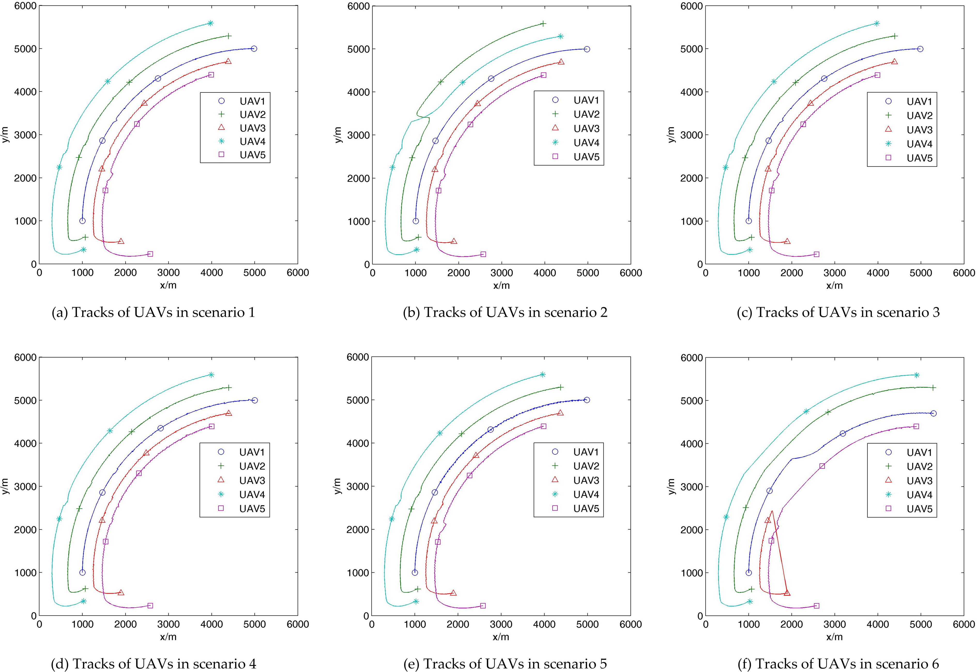
Tracks of all UAVs on the horizontal plane, respectively, in six communication fault scenarios. UAV: unmanned aerial vehicle.
As shown in Figure 8(a) and (c), when link interrupt occurs in e12 and e13, or the unicast transmitter failure occurs in UAV1, UAV2 and UAV3 cannot receive the information from UAV1, and can only maintain their current speed and heading angle. Therefore, they begin to deviate from their correct trajectory. Meanwhile, UAV4 and UAV5 also begin to deviate from their correct trajectory, since UAV4 follows UAV2, and UAV5 follows UAV3. After Tactive seconds, all UAVs switch to the reconfigured communication topology and the formation shape is quickly recovered. Further, the reoptimized communication topology is the same as the reconfigured communication topology, so the formation shape is kept until the end.
As shown in Figure 8(b), when the unicast transmitter failure occurs in UAV2, UAV3 and UAV4 cannot receive the information from UAV2, and they begin to deviate from their correct trajectory. UAV5 also begins to deviate from its correct trajectory since it follows UAV3. After Tactive seconds, all UAVs switch to the reconfigured communication topology and the formation shape is quickly recovered. Further, after getting the reoptimized communication topology, UAV2 and UAV4 exchange their positions, and then the formation shape is kept until the end.
As shown in Figure 8(d), when the unicast receiver failure occurs in UAV4, UAV4 cannot receive the information from UAV2 so it begins to deviate from its correct trajectory. After Tactive seconds, all UAVs switch to the reconfigured communication topology, where UAV4 is the new formation leader, and the formation shape is quickly recovered. Further, the reoptimized communication topology is the same as the reconfigured communication topology, so the formation shape is kept until the end.
As shown in Figure 8(e), when the unicast transceiver failure occurs in UAV1, UAV1 soon flies up to another height
As shown in Figure 8(f), when the broadcast transmitter failure occurs in UAV3, UAV3 soon flies up to another height
Conclusions
During the UAV formation flight, one or more UAVs may encounter some communication faults, which can cause those UAVs to become unable to keep the original formation shape. Accidental UAV collisions could also occur. Therefore, this article proposes a novel fault-tolerant communication topology management method for the leader–follower UAV formation to guarantee the safety of all UAVs and continue keeping the formation shape under multiple types of communication faults. This method is composed of three algorithms, which are based on Edmonds’ algorithm for the MCA problem in graph theory.
Given a formation shape before the formation flight, this method uses a directed weighted graph to describe all available communication links in the formation, and uses algorithm 1 to achieve the MCA of this directed weighted graph (i.e. the optimal initial formation communication topology with the minimum formation communication cost). When some communication faults occur, this method first deletes the faulty nodes or arcs in the original directed weighted graph, and then uses algorithm 2 to achieve the MCA of this modified directed weighted graph (i.e. the reconfigured and suboptimal formation communication topology), which can help all UAVs to maintain safety from collision and quickly recover the original formation shape. After the communication topology reconfiguration, this method uses algorithm 3 to reoptimize the communication topology by reconfiguring the UAV positions in the formation shape, and then continue keeping the formation shape. Simulation results have verified the effectiveness of this method.
Future research directions include (1) a fault-tolerant communication topology management method under communication faults for other types of leader–follower UAV formation that uses a new formation control method as in the studies of Hou and Fantoni and Park et al. and (2) a fault-tolerant communication topology management method under communication faults for the virtual structure-based and consensus-based UAV formation.
Footnotes
Declaration of conflicting interests
The author(s) declared no potential conflicts of interest with respect to the research, authorship, and/or publication of this article.
Funding
The author(s) disclosed receipt of the following financial support for the research, authorship, and/or publication of this article: This research is supported by the National Natural Science Foundation of China (71401048, 71671059, 71521001, 71690230, 71690235, 71472058), the Anhui Provincial Natural Science Foundation (1508085MG140), and the Fundamental Research Funds for the Central Universities (JZ2016HGTB0726).