
Abstract
This article presents a strategy for hand-free control of an NAO humanoid robot via head gesture detected by Google Glass-based multi-sensor fusion. First, we introduce a Google Glass-based robot system by integrating the Google Glass and the NAO humanoid robot, which is able to send robot commands through Wi-Fi communications between the Google Glass and the robot. Second, we detect the operator’s head gestures by processing data from multiple sensors including accelerometers, geomagnetic sensors and gyroscopes. Next, we use a complementary filter to eliminate drift of the head gesture reference, which greatly improves the control performance. This is accomplished by the high-pass filter component on the control signal. Finally, we conduct obstacle avoidance experiments while navigating the robot to validate the effectiveness and reliability of this system. The experimental results show that the robot is smoothly navigated from its initial position to its destination with obstacle avoidance via the Google Glass. This hands-free control system can benefit those with paralysed limbs.
Keywords
Introduction
Since the 20th century, intelligent robots have been applied into various fields due to the development of human machine interaction (HMI) technology to effectively apperceive the environment for dynamic decision-making and planning, behavior control and execution. More and more scientists are researching on it. For example, Liu et al. proposed a novel object recognition method using visual–tactile fusion information based on a sparse coding method 1 –3 , which greatly improves the object recognition accuracy; Li et al. designed a grasping posture control for a robotic arm based on novel adaptive particle swarm optimization, which made the object grasping of home service robot quicker and more accurate 4 . Nowadays, most of the existing HMI methods rely on the operator’s hands. Zhang et al. adopted a commercially available, standard joystick as the candidate HMI device of the robot 5 ; Speers et al. achieved the goal of controlling Robot Operating System-enabled robots by sending commands from the lightweight tablet 6 ; Ochiai et al. proposed a remote control system to achieve the autonomy of multiple mobile robots using touch panel interface. 7 However, with the technology development demands, the operation tasks have become more and more complicated. For instance, using a multi-robot system to perform, a complex process demands an operator’s attention constantly shift among various tasks to maintain the necessary awareness of a given situation, such as exploring environments and locating targets simultaneously, 8 –10 and manipulators fitted into the ‘Jiaolong’ deep manned submersible vehicle have to collaborate with each other to complete a complex task. 11,12 In addition, target capture is an essential and key mission for the tethered space robot, which requires controlling a gripper, a space tether and a space platform at the same time. 13 –15 Using those techniques, a single operator has to adopt multiple cooperated patterns to complete the complex operational tasks. In order to avoid investing extra manpower and material resources, it has become necessary to find a new way to increase sources for generating control signals and efficiently representing their control intentions.
The wearable technology that appeared in 2012 has drawn the attention of researchers and engineers to exploring its application (APP) into the field of HMI, for example, a useful head mounted mouse for people with paralysed limbs, 16 a wearable technology-based electric-powered wheelchairs for disabled people 17 and a gel spat as a device walking assistance for old folks. 18 In the same year, Google Glass, called ‘expanding reality’ glass, was released by Google Inc. This device with powerful data processing ability and a wearable advantage has been applied to achieve great results in some areas. Jeroudi et al. compared the accuracy among four types of electrocardiogram (ECG): ECG interpretation on a Google Glass screen, a photograph of the ECG taken by Google Glass and displayed on a mobile device, the original paper ECG and a photograph of the ECG taken with a high-resolution camera and displayed on a mobile device 19 ; Rahimy and Garg recorded a scleral buckling surgery process using the video recording function of Google Glass 20 ; Wille et al. validated that there was no significant difference in subjective strain between wearing Google Glass or using a Tablet-PC when people were asked to follow a toy car assembly instructions while monitoring a virtual gauge 21 ; in the field of acoustics, Weppner et al. developed a fully functional APP prototype gPhysics App to perform an educational physical experiment based on the Google Glass platform 22 ; Kapellmann-Zafra et al. used Google Glass for a guided swarm of robots to transport a large object in an environment with obstacles. 23 Our team, which is one of the pioneers, has reported preliminary research outcomes on the robot control via Google Glass. 24 –26
In the previous research, 24,25 we adopted the rotation vector sensor to calculate the angle change of the rotation matrix and transfer these angle changes to the control intentions. A critical problem that gave users a poor experience during our study was that the head reference position had significantly drifted during operations, which probably caused the failure of robot control. In this article, we use a complementary filter to fuse data measured by an accelerometer, a geomagnetic sensor and a gyroscope to update the operator’s head reference gestures. Consequently, the reference drift is eliminated and the robot control performance is improved.
‘Google Glass-based robot control system’ section introduces the Google Glass-based hand-free control system we developed, consisting of a Google Glass and an NAO humanoid robot. ‘Head gesture detection’ section describes how to detect a head gesture using the complementary filter. ‘Controller design’ section presents the design procedure of controlling the humanoid robot via the Google Glass. ‘Threshold selection and experiment validation’ section discusses the threshold selection through an offline experiment and arranges an obstacle avoidance experiment to demonstrate the performance of this system. Finally, ‘Discussion’ section compares the proposed method with the others based on the rotation vector sensor and discusses further research activities.
Google Glass-based robot control system
Here, we briefly introduce the hand-free control system that consists of a Google Glass and an NAO humanoid robot, as shown in Figure 1. 25 On the Google Glass, we developed a detection section using the Java language. This section detects the operator’s head movement, that is, head gesture, which represents an operator’s intent, converts the intent into the corresponding control command and transmits the command to the robot. This section also has a user interface (UI) to display the command and the head gesture of the operator. On the robot, we designed a robot controller to receive instructions from the Google Glass, make the robot execute the corresponding behavior and feed the live video to the UI on Google Glass which allows the operator to make proper decisions.

Google Glass-based robot control system.
Google Glass
Google Glass supports Wi-Fi and Bluetooth and is mainly composed of six sections: a GPS, a camera, a prism, a speaker, a microphone and a battery, 27 as shown in Figure 2(a). It runs on the operating system Android 4.4.2 (KitKat) with an OMAP 4430 SoC1.2 GHz Dual Core (ARMv7) processor produced by Texas Instruments and uses the optical head mounted display projection principle to realize ‘primary amplification’ for displaying information. The micro projector casts light on the reflective screen. The light reflected through the convex lens creates a large virtual screen and displays text and various data in front of the eyes. The projection of the layer is equivalent to a 25-in high-definition screen from 8-feet away, as shown in Figure 2(b). Moreover, a touchpad, located on the external part of the CPU case and on the right side of the device, supports multi-touch interaction. It is possible to identify the gestures of single or double tap and swiping a user’s finger in a specific direction. 27 –29

(a) Structure of Google Glass. (b) Superimposed layer diagram.
The main UI on Google Glass is called timeline which is a set of 640 × 360 pixel cards organized into sections, including ‘home’, ‘past’ and ‘present and future’. Compared with other wearable devices, Google Glass offers various control options for the user. Moreover, Google Glass supports three types of Glassware, such as Mirror Application Program Interface (API) Glassware, GDK Glassware and Hybrid Glassware. 27 –29 In this study, the GDK Glassware is used to explore an APP to control the NAO humanoid robot.
Google Glass is also equipped with a variety of sensors, including accelerometer, gyroscope, geomagnetic sensor, direction sensor and rotation vector sensor, which are divided into software-based sensors and hardware-based sensors. 30
NAO robot
The NAO humanoid robot, as shown in Figure 1, is 57 cm in height and 4.5 kg in weight and was developed by the Aldebaran Robotics company in 2006. It is designed with 25 degrees of freedom (DOFs), namely, 11 DOFs for the lower part that includes the legs and pelvis and 14 DOFs for the upper part that includes the trunk, arms and head. Each leg has two DOFs at the ankle, one DOF at the knee and two DOFs at the hip, and each arm features two DOFs at the shoulder and two DOFs at the elbow. Besides, it has one DOF at the wrist and one additional DOF for the grasping ability of the hand. The head can rotate about the yaw and pitch axes. The kinematic details are shown in Figure 3. The NAO uses brushed DC motors with magnetic rotary encoders for position feedback. 31

Detailed kinematics of NAO and wrist joint not represented.
The NAO is provided with an open-loop walk engine to generate and stabilize walking and uses the industry-standard zero moment point (ZMP). ZMP is defined as the point on the ground at which the net moment of the inertial and gravity forces have no component along the horizontal axes. The ZMP trajectory is calculated from user specified step parameters and transformed into a center of gravity (CoG) trajectory using an inverted pendulum model. This CoG trajectory is then tracked and maintained throughout single and double support phases using inverse kinematics. The swing leg trajectory is a cycloid. 32
Additionally, the NAO robot supports Ethernet or Wi-Fi, microphones, cameras and various sensors, such as ultrasonic, tactile\touch, force sensing resistors, gyroscope and accelerometer. 33 These features provide convenience for users to develop a variety of APPs. Based on the Linux operating system, the NAO humanoid robot makes users easily design different types of behaviors with the NAOqi which plays as the API and the framework. Furthermore, a lot of third-party software packages support the programming of the NAO humanoid robot. For instance, Choregraphe and WEBOTS separately offer graphical programming tools and powerful simulation models. 34
Head gesture detection
Raw sensor data
The head movement detection is the key to our robot control strategy, which is achieved by calculating the head gesture via a complementary filter, consisting of a low-frequency filter and a high-frequency filter, to fuse the data measured by an accelerometer, a geomagnetic sensor and a gyroscope, as shown in Figure 4. In order to describe a head gesture, a three-dimensional space coordinate system needs to be defined, and the method of space vector transformation is adopted. Then, on the Google Glass, a sensor device coordinate system, called X-Y-Z, and a global coordinate system, called x-y-z, are defined using the Android operating system, whose relationship is shown in Figure 5. We use Euler angles (pitch, yaw and roll) to describe a head gesture which represents the transform relationship between the device coordinate system and the global coordinate system. 35

Multi-sensor schematic diagram.

Sensor coordinate system of Google Glass.
There are two methods for calculating a head gesture, respectively: the first one is based on the accelerometer and geomagnetic sensor, and the second one is based on the gyroscope. The API of the Android operating system provides a SensorManager class and a SensorEventListener interface which help access these sensors, listen to the sensor data changes and process the measured data. Thus, we are able to obtain the data measured by the accelerometer, geomagnetic sensor and gyroscope to build a rotation matrix R through the sensor data as follows


Fusion of sensor data
As discussed above, the raw data is acquired by the multiple sensors. However, like any normal Android device, the accelerometer and geomagnetic sensor on Google Glass deliver significant noise, while the gyroscope provides a low-noise angle signal due to the integral over time but the integrated gyroscope data may quickly become non-physical, which means the integrated data does not correctly represent the actual orientation of the device. In the frequency domain, the former sensor signals are significantly affected by noise with high frequency, while the latter sensor signal includes a drift in low frequency, 35,36 as shown in Figure 6. As a result, these raw sensors’ data cannot be precisely used to calculate the operator’s head gestures.

(a) Noise from accelerometer and magnetometer signals. (b) Drift of gyroscope.
In order to improve the accuracy of the head gestures, the following sensor fusion algorithm based on a complementary filter is proposed to remove the high-frequency noise and to eliminate the drift in low frequency, separately, and then to combine the processed signals. The complementary filter is a popular sensor fusion method, as shown in Figure 7. This method can remove high-frequency noise and eliminate the drift with low frequency in parallel. Let’s suppose the true value of signal C(s) is measured in two different ways, so two measurements of data C1(s) = C(s) + μH
(s) and C2(s) = C(s) + μL
(s) are obtained, respectively, where μH
(s) is a high-frequency noise and μL
(s) is a low-frequency noise. Assuming that the transfer functions of a high-pass filter and low-pass filter are defined as GH
(s) and GL
(s), respectively, which construct the complementary filter system under the following condition


Principle of complementary filter.
The output from the complementary filter shown in Figure 7 is

In this study, we will develop the sensor fusion system based on the complementary filter to eliminate the angle drift integrated by the gyroscope and the data noise delivered by the accelerometer and geomagnetic sensors, as shown in Figure 8. The latest signal data from the accelerometer and magnetometer are stored in AM(n), while the latest gyroscope data are stored in G(n). Here, dT is the integral interval for processing the gyroscope data. Then, the output Y(n) from the sensor fusion system is calculated by
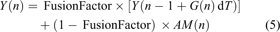

Process of sensor fusion.
where the parameter FusionFactor is the weight that affects the response rate and proportion of the sensor data processed by both the high- and low-frequency filters. It can be calculated by
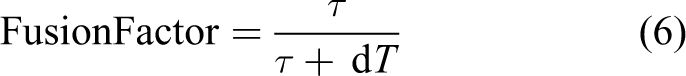
where the parameter τ is the time constant for both the low-pass and the high-pass filters. Here, we select the parameter FusionFactor as 0.9. This is because we want to primarily use the gyroscope data and to use a fast gyroscope measurement time dT, so the gyroscope doesn’t drift more than a couple of degrees before the next measurement is taken. 35,36 FusionFactor also plays an important role in achieving a good control quality of this system.
Head gesture detection based on sensor fusion
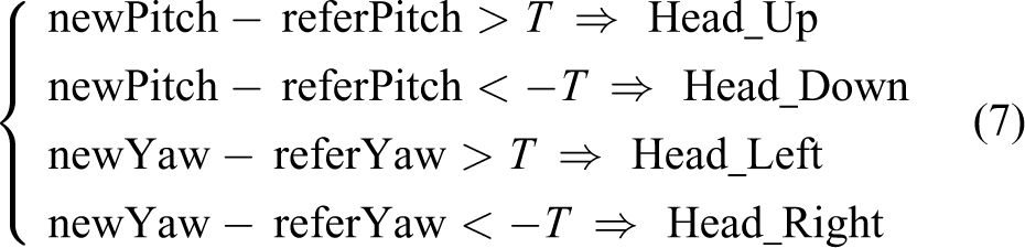
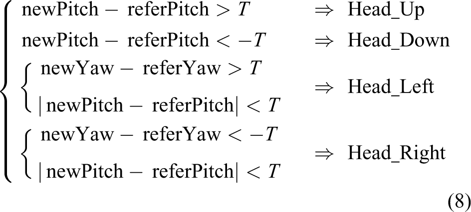
In this remote system, four control instructions correspond to the four types of head gestures, respectively: head up, head-turning left, head-turning right and head down. Because these head movements mainly change the value of the pitch and yaw, only these two values are investigated. When an operator makes the four kinds of head movements mentioned above and returns to the original position, then all sensor data is recorded during the movements, as shown in Figure 9. The blue and red lines, respectively, represent the pitch and yaw. Through selecting an appropriate threshold, all the head movements can be easily distinguished after the interferences from drift and noise are eliminated. In order to accurately detect a head gesture, we select a reference position which is the head position when the operator looks straight ahead and records the head gesture at this position, denoted as referPitch and referYaw. Then, any head gesture is configured by new pitch and yaw values detected by the sensors, denoted as newPitch and newYaw. In doing this, a threshold T is selected to identify the head gesture according to the ideal discrimination rule below

Measurement data of four kinds of head movements.
Controller design
Command generation APP
On the Google Glass, we program a robot tele-control APP using GDK Glassware development style. This APP mainly achieves three types of functions as shown in Figure 1, respectively: (1) detecting head gesture and converting and sending instruction; (2) displaying head gesture and (3) live video feedback. They are running on three threads, namely, Thread_1, Thread_2 and Thread_3, to reduce interference and ensure the program works smoothly. During the control process, Thread_1, named Head Gesture Detection Thread, detects the operator’s head gesture, converts it to its corresponding control instruction and sends the instruction to the robot. Thread_2, named UI Thread, displays the operator’s head gesture on the UI. Thread_3, called Video Thread, constantly sends the character ‘I’ to get live video about the environment and displays it on the UI. The whole process is shown in Figure 10(a).
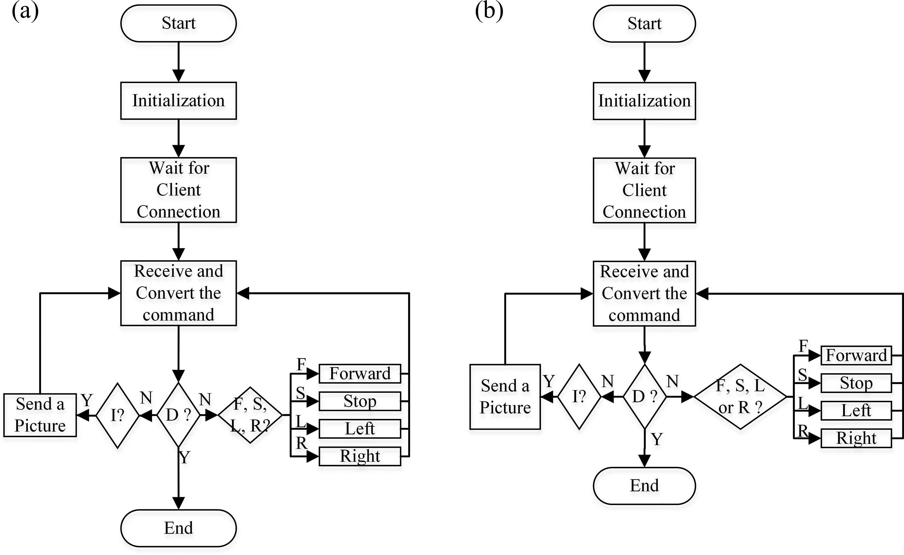
(a) Controller of Google Glass. (b) Controller of NAO robot.
Controller for NAO robot
A controller, which runs on the NAO humanoid robot, is developed using the C++ language under the Linux environment and includes two functions running on different threads: instruction receiving and behaviour performing. In order to achieve instruction receiving, the socket TCP protocol is applied to build communications between the Google Glass and the NAO Robot. Here, the robot acts as the server port, while the Google Glass is the client port. The server receives the instruction from the client in the form of input stream. At the same time, the controller parses six types of character instructions: ‘F’, ‘S’, ‘L’, ‘R’, I and ‘D’, and their definitions are listed in Table 1. During the entire control process, the robot needs to continuously listen on the bound port in order, so that it is able to obtain the instruction from the client on time, as shown in Figure 10(b).
Definition of commands.

Threshold selection and experiment validation
It is critical to select a threshold to cut off invertible activities of the operator head, hence we generate head gesture data without control of the real robot. Then, we arrange an online experiment to validate the performance, in which an operator needs to navigate the NAO robot from its initial to its destination with obstacle avoidance.
Threshold selection
In this part, in order to find out a reliable threshold, we use the offline experiment to analyze all the data while the operator is moving his/her head. During the experiment, the operator wearing the Google Glass follows instructions and completes corresponding head movements. These instructions’ including Head_Up, Head_Down, Head_Left and Head_Right are randomly generated and displayed on the glass screen. A total of 50 instructions are executed and the interval between instructions is 5 s. Figure 11 shows the recorded data of angle changes plotted in a chart.

Chart of experimental data.
Figure 11 shows that reset errors are usually between ± 10° because of an invertible activity of the operator’s head and hardly accurately returning the reference position as indicated by the yellow lines. The minimum angle change yielded by the operator head movement is about ± 40° as indicated by the two black lines. So, a threshold of 10°–40° can be selected which can identify all head movements with the accuracy of 100%. Moreover, we find that the Head_Up and Head_Down movements’ change both of the pitch and yaw values as enclosed in the black rectangle in Figure 11. So, we modify the discrimination rules by considering the condition: When the yaw value triggers a rule, it is essential to check if the pitch value satisfies the rule. In this study, we use the rules in equation (8) to distinguish operator head movements. In order to obtain more measurement margins, we set threshold T as ± 25°, as indicated by the green lines
Robot navigation with obstacle avoidance
In order to validate the effectiveness of the designed system, we navigate the robot from its initial position to its destination with an obstacle avoidance experiment. First, we set a connection between Google Glass and the NAO humanoid robot. Second, we configured some initial parameters (generally, the natural position of the robot head). Third, wearing the Google Glass, the operator was able to navigate the NAO humanoid robot to pass through several narrow paths and finish obstacle avoidance with the assistance of the feedback of live videos.
The experimental scene and navigation mission are shown in Figure 12. For an ideal case, the controller just needs five kinds of commands to guide the NAO robot through the tangential paths, namely, one straight forward going, two left turnings, two right turnings and one stop at the destination. While in realistic cases, more control commands are needed in the process of walking because of the limitation of the humanoid robot’s flexibility. In our experiment, the number of commands is eight forward going, two left turning, five right turning and one stop, as shown in Table 2. This is because the operator needed more commands to adjust the deviation of the robot when finishing the navigation task.

Experimental scene.
The number of the commands.

Discussion
The method proposed in this article is a novel scheme based on multi-sensor fusion of Google Glass. It is the integration of wearable technology and robot control. Thus, the operator has a feeling of interaction with the expanding reality glass and experiences hand-free control missions. Meanwhile, a new channel to convey the control intention is mined, and the source of control signal is enriched. It makes it possible to accomplish a variety of control missions at the same time. Moreover, there are some significant advantages for this method as follows:
Compared with the traditional control system which relied on the computer monitor to watch the video feedback, the image of Google Glass is directly projected on the operator’s retina. Therefore, this system fits the human’s habits better, gives the operator a stronger sense of immersion, alleviates the burden of control and improves the control efficiency.
Compared with the joystick control system without video feedback, the controlled robot does not have to be in sight.
Compared with the control system relying on a handheld mobile device, the control system is able to navigate the humanoid robot with the operator’s hands released and relieve hand fatigue due to operating equipment for a long period.
Compared with the control system based on a rotation vector sensor, the head gesture reference drift does not occur, and the user experience has been greatly improved.
The system based on Google Glass is more portable due to the wearable feature, and the switching of different control commands is smoother and more natural.
When facing a complex task, the operator can easily achieve robot remote control without the need for his/her hands. At the same time, it is understood that his/her hands can do other jobs.
It is significant for people with paralysed limbs that this system can help them do many tasks which would normally depend upon their limbs.
This research intends not only to test the possibility of using a Google Glass to remotely control a humanoid robot but also inspires and accumulates data on how to develop a hands-free control system for those with paralysed limbs. In the future, we will explore the human machine interface based on head gestures with the integration of other interaction methods, for example, voice controls to make robot control easier and more convenient.
Footnotes
Declaration of conflicting interests
The author(s) declared no potential conflicts of interest with respect to the research, authorship, and/or publication of this article.
Funding
The author(s) disclosed receipt of the following financial support for the research, authorship, and/or publication of this article: This work was supported by the National Natural Science Foundation of China under the grant 61473207.