
Abstract
In this article, a set of integrated ground target tracking flight system has been proposed based on the Qball-X4 quad-rotor unmanned aerial vehicle hardware platform and the QuaRC software platform. Both of the hardware and software platforms are developed by Quanser Company, Canada. The proposed tracking and positioning algorithm could be divided into several stages. First, a tracker is developed based on an optical flow method to track the target; and then, in order to improve the reliability of tracking algorithm and also help in retrieving the lost target, a cascade target detector is developed; meanwhile, a model updated scheme aiming at some possible errors in tracking and detecting process is presented based on Positive-Negative (P-N) learning system; at last, a monocular visual positioning system is designed based on the corresponding navigation message. In addition, the effectiveness of the proposed flight control system is verified by both simulation and hardware-in-loop system results in several tracking flight tests.
Introduction
Unmanned aerial vehicle (UAV) is a special kind of aircrafts which can accomplish takeoffs, landings, cruising and the like tasks automatically without human operating actions. 1,2 Because UAVs have some specific characteristics like zero mortality (no driver is needed), low production cost and so on, they have been widely accepted in both military and civilian fields. Military UAVs can be used in intelligence reconnaissance, cargo transportation, armed attacks and so on. UAVs also appear frequently in aloft works, forest fire fighting, pesticide spraying and some other civilian fields. 3
Nowadays, UAVs develop fast towards the direction of smaller and minitypes along with the rapid developments of automatics, computer technology and components manufacturing technology. Among various kinds of UAVs, the minitype multirotor UAV plays a more important role due to its specific characteristics of minimize, light quality, high stationarity, low altitude flight flexibility, operability and so on. It could be used in aerial photography, supervisory control and even parcel delivery. 4 –6 With the improvements of modern technology, the ubiquitous cameras combined with efficient intelligence algorithms in target searching and tracking are taking the place of our binoculars gradually. Moreover, if the cameras are placed on UAVs, the horizon of human will be expanded to anywhere UAVs could arrive, which could significantly advance human developments. UAVs are also favourable research platforms to verify control, navigation, route planning, tracking and target recognition algorithms. 3,7 –9
There have already been some remarkable achievements in UAVs research fields. Amidi et al. of Robotics Institute in Carnegie Mellon University have proposed a visual odometer to estimate the real-time state motion equation of UAVs, which successfully solved the self-positioning problem when the UAVs lost their sensor (like Global Position System (GPS) and gyroscope) signals. 10,11 Saripalli et al. of the University of Southern California developed a kind of AVATAR small-size UAV and presented an autonomous landing approach based on Hamiltonian’s equation on the this platform. The proposed control algorithm could achieve flight tracking and autonomous landing when the target is keeping static or moving very slowly. 12,13 An OATS air target tracking system was presented by Helble and Cameron from the University of Oxford on a unmanned helicopter platform. This control system was achieved by an automatic flight control system which could control all the gestures and motions of the unmanned helicopter in the air. 14 Moreover, some agricultural applications of UAVs have been achieved by Chen et al. of the University of California, Merced. 15 –17
In this article, we proposed a set of integrated ground target tracking flight control system based on the Qball-X4 quad-rotor UAV hardware platform and the QuaRC software platform. There are several stages in achieving the proposed tracking and positioning algorithm. First, a tracker was developed based on an optical flow method to track the object; then, in order to improve the reliability of tracking algorithm and also help in retrieving the lost target, a cascade target detector was developed; meanwhile, a model updated scheme aiming at some possible errors in tracking and detecting process was presented based on Positive-Negative (P-N) learning system; and at last, a monocular visual positioning system was designed based on the corresponding navigation message.
The mathematical models of the UAV are quite complicated, and we have already discussed them in the study by Pan et al., 18 so we won’t redescribe them in this article. The rest of this article is organized as follows. “Semi-physical simulation platform” section includes the hardware and software components; then, the details of the proposed tracking and positioning algorithm are illustrated in the “Qball-X4 tracking and positioning algorithm design” section; “Semi-physical simulation platform configuration and experiments” section shows the results of both simulation and hardware-in-loop flight tasks as well as some discussion of the results; finally, the conclusion is given in the last section.
Semi-physical simulation platform
The platform we used in this article is developed by Quanser Company, Canada, which can be connected to real object and accomplish real-time control mission.
Hardware platform
The experimental platform in this article is the Quanser unmanned vehicle systems 19 that includes a Qball-X4 quad-rotor UAV, a ground robot, six wireless Complementary Metal Oxide Semiconductors (CMOS) cameras, a wireless image transmission receiver, OptiTrack positioning system and a Personal Computer (PC) processor.
Qball-X4 quad-rotor UAV and visual platform
Qball-X4 is an innovative experimental platform which was developed by Quanser Company for UAV research. The structure of Qball-X4, its bottom CMOS camera and the Qbot ground robot are shown in Figure 1. The details of its parameter configuration can be found in the literature. 20

(a) Qball-X4 UAV, (b) its bottom CMOS camera and (c) Qbot ground robot. UAV: unmanned aerial vehicle; CMOS: Complementary Metal Oxide Semiconductors.
Qball-X4 quad-rotor UAV doesn’t carry a camera itself, but it has a reserved Universal Serial Bus (USB) port for an external USB camera. Because the serious bandwidth occupation of image transmission may impact the normal flight performance of UAV, we use an external wireless camera here which locates at the central bottom of Qball-X4 as shown in Figure 1(b).
OptiTrack positioning system
The ordinary civilian GPS couldn’t satisfy our experiment requirements because it has relatively bigger positioning error. Therefore, we use the OptiTrack positioning system here. The position is got by a camera in OptiTrack system and precision could be within 1 cm. The details of the camera parameters can be found in the literatute. 20
In our experimental platform, there are six cameras which distribute parallelly on both sides of the laboratory wall. The cameras are located on the top of the wall and are closed to the ceiling. In this way, we can get the best view of the laboratory, and the repeated coverage areas of the cameras could be set as big as possible.
Ground PC processor
The main function of the ground PC processor in this article is the design and compilation of the corresponding control system. As the host of QuaRC, it can achieve the location information of Qball-X4 from OptiTrack positioning system. And it will obtain and handle with the image information from wireless image transmission, then transfer the target location information to Qball-X4 (QuaRC target) by Wi-Fi.
Software platform
The software platform in this article is the QuaRC system, which is the evolution of WinCon. It is compatible and can also be integrated to MATLAB/Simulink system. In this article, the default communication setting of Qball-X4 is a temporary point-to-point wireless network based on Transmission Control Protocol/Internet Protocol (TCP/IP) protocol.
Qball-X4 tracking and positioning algorithm design
In this section, a tracking and positioning algorithm aiming at the characteristics of Qball-X4 is proposed. The details of the four stages in this algorithm are introduced in the below subsections.
Tracker design based on optical flow
Optical flow is a kind of image motion expression, and it is also defined as the apparent motion pattern of image brightness. In this article, the Lucas–Kanade optical flow tracking method based on local restrictions is used to design the tracker. 21 On this basis, the median flow tracker based on the normalized cross correlation (NCC) function is also applied to filter 50% of unreliable tracking points to improve tracking precision.
The input of the tracker is a pair of images It, It + 1 and a target labelling patch bt, and the output is the target patch bt + 1. A series of gird points are first initialized in target labelling patch bt. Then, a discrete optical flow field will be generated between It and It + 1 by a Lucas–Kanade tracker. After that, the forward and backward error and similarity NCC will be calculated for each grid point, and those points whose error is larger than the median and NCC is smaller than the median will be filtered out. The left tracking points will be used to estimate the displacement of the target patch according to the median of every spatial dimension.
Cascade target detector design
After achieving the target tracker, we need to do the following detection on the tracking target. The target detector we proposed in this article is a cascade one based on sliding patches. The sliding patches are generated according to the size of entire image and the size of initialized target box. Some different sizes of patches will be generated, and each box is labelled by its upper left and lower right points. The sizes of the boxes range from integral multiples of 1.2− 10 to integral multiples of 1.210. So, there will be 21 scale dimensions here, and the interval of each neighbouring patches pair is 0.1 multiple of patch width or height as shown in Figure 2.
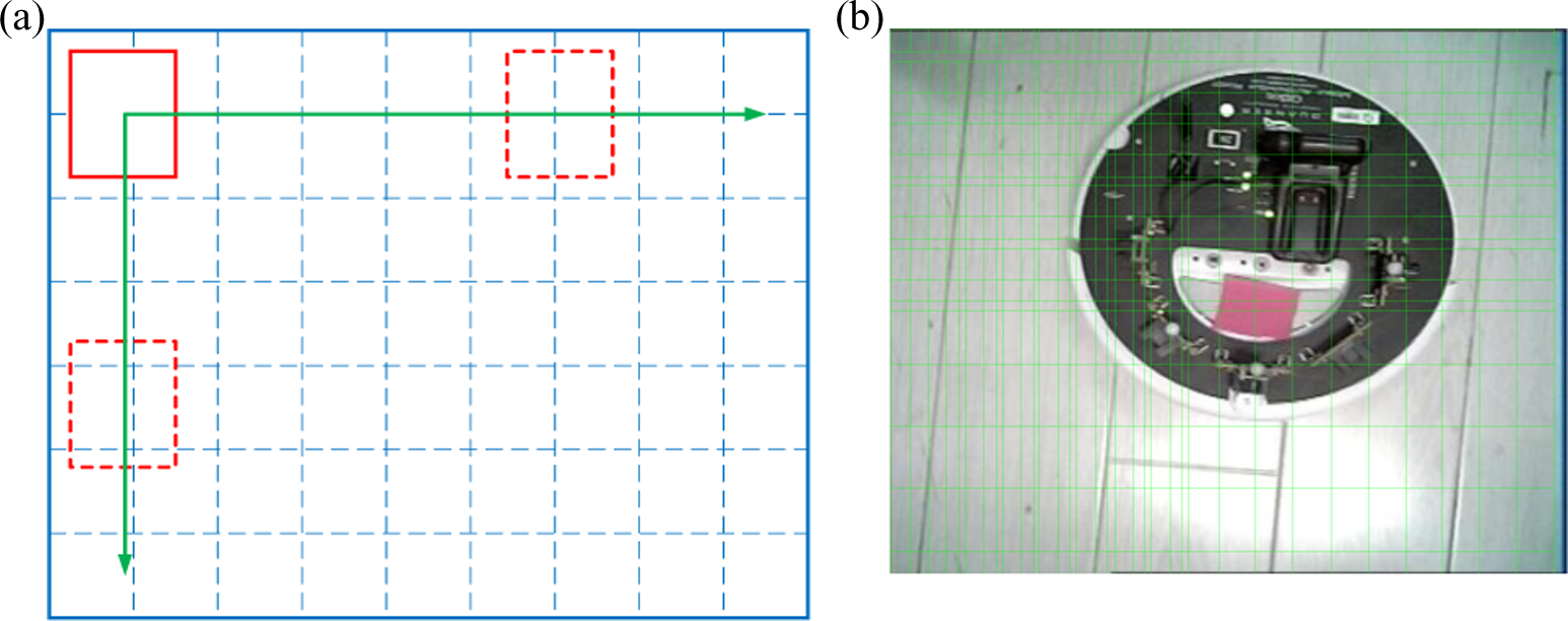
Schematic diagram of generated patches. (a) Dimensional patches generate method. (b) Ground robot generated patches.
In this article, the detector design procedure can be divided into three stages as illustrated in Figure 3.

The flow diagram of target detection process.
Variance classifier
Designing a variance classifier is the first stage of our detection process. In this stage, all the image patches whose grey value variance is smaller than 50% of the tracking image grey value variance are refused by the classifier. The grey value variance of an image patch p can be written as

In order to make programming process simpler, we use the incremental form in actual computation as follows

Because any arbitrary image patch p can be expressed by its upper left coordinate point

The application of integrogram will speed up the program, so we can recognize the background image patches in a short time. In this stage, 50% of the nontarget patches will be filtered out, and this can speed up our target detection process obviously.
Random forest classifier
The second stage of the detection process is designing a corresponding random forest classifier whose input is the image patches passed through the above variance classifier. There are 10 decision trees in the random forest classifier. Each decision tree has 13 nodes. All the nodes will be put in feature matching process based on binary robust independent elementary features (BRIEF). If the match is successful, the output will be one; otherwise, the output will be zero. 23 The BRIEF image feature code conversion process in our task is presented in Figure 4.

BRIEF code conversion process of a patch. BRIEF: binary robust independent elementary features.
Nearest neighbour classifier
The majority of the negative image patches will be filtered out in the above two stages, but there still will be about 50 doubtful patches left. We use the nearest neighbour classifier to recognize these doubtful patches at last. Define the similarity of two image patches

The positive nearest neighbour similarity, namely the similarity between one image patch and the target, is defined as follows
On the contrary, the negative nearest neighbour similarity, namely the similarity between one image patch and the background, is defined as follows

The positive nearest neighbour similarity between one patch and the first 50% positive patches can be expressed as follows

The relevant similarity is defined as follows

Note that for one image patch, the larger the value of Sr is, the larger possibility of background patch will be.
Then, the conservative similarity is denoted as follows

The larger value of the conservative similarity value means the larger possibility of being recognized as target patch compared to the first 50% positive samples. For one of the left patches, if its
Model updated scheme design based on P-N learning system
There is always an assumption in the tracking process that frame motion is finite and target is usually visible. However, if the target moves out of the camera visible area, the tracking task may be losing and never recovered again. There are also two kinds of mistakes which happen a lot in detection process, namely truth abandon and illusion adoption. Therefore, when the tracker and detector make mistake at the same time, the task will be totally failed. In order to avoid these kinds of mistakes and maintain continuously tracking, a learning system is added into our control scheme. The learning system is used to estimate the detector mistakes through performance observation of the tracker and detector. And it also generates updated training target model samples to avoid the appearance of the same mistake in the following tracking process. 24
Monocular visual positioning system design
Camera parameters calibration
In this article, the camera parameter calibration task has been accomplished by the camera calibration toolbox in MATLAB2014b. The calibration method embedded in this toolbox was proposed by Heikkila and Silvén. 25 The calibration pattern in this method is a 6 × 8 black and white checkerboard pattern. All the black and white pieces in the checkerboard are squares with 20-mm side length.
Then, we took 28 pictures of the checkerboard from different locations as well as different angles.
The location information of these 28 images and the camera could be displayed under the camera coordinate as shown in Figure 5. The camera intrinsic parameter matrix is obtained as follows

where
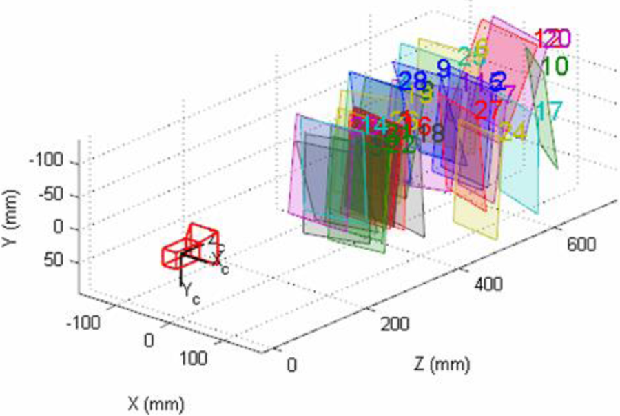
The checkerboard positions displayed in camera coordinate.
Target position calibration
In the tracking process, target should always stay around the middle of the horizon of Qball-X4. Therefore, target position calibration will be needed in the camera coordinate if rolling angle or pitch angle is not zero. The calibration will eliminate the bad impacts brought by the changes of rolling angle or pitch angle.
Qball-X4 UAV has a central axisymmetric orbicular structure, and its camera stays in the middle of its bottom. Therefore, if the height of Qball-X4 to the ground doesn’t change, the included angle of the target and the Z-axis in world coordinate UW won’t change, 18 so the UAV won’t be impacted by the changes of rolling angle or pitch angle. In this article, we define an auxiliary coordinate UA according to the invariable included angle as presented in Figure 6. In this coordinate, the original point OA is decided by the camera location, namely the horizontal centre of Qball-X4. The positive direction of Y-axis is the horizontal component of the heading direction of Qball-X4. And the XAOAYA plane is always perpendicular to the Z-axis of world coordinate UW. In this way, the information of pitch angle, rolling angle, yawing angle and height collected by GPS system will be calibrated from the camera coordinate to the centre of the auxiliary coordinate UA.

Auxiliary coordinate system.
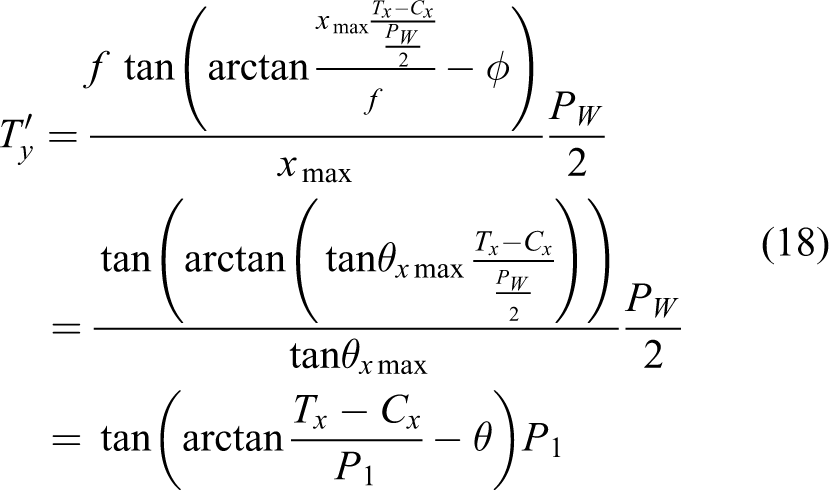
In this article, the ideal shooting angle of the camera is downward vertical to the ground. In the camera coordinate, assume that the width and height of image are PW (pixel) and PH (pixel), respectively; the physical focal length of camera is f (millimetre); the width and height of Charge Coupled Device image device are 2xmax (millimetre) and 2xmax (millimetre), respectively; and the transverse view angle and lengthways view angle are
The parameter relationship of X-axis direction in the camera coordinate can be obtained as follows

Similarly, that of the Y-axis is as follows

Therefore, the conversion equation from pixel unit to length unit can be achieved as follows

where x, y are the lengths whose unit is millimetre, and P is the length whose unit is pixel. The conversion equation is used for the calculation of actual target location, namely transferring the location coordinates on images into actual space location coordinates.
Thus, the target location calibration could be accomplished by converting the target location coordinates from camera coordinate system to auxiliary coordinate system. Assume the UAV is flying with a pitch angle θ as presented in Figure 7, where the centre location under the camera coordinate system is (Cx, Cy), and its corresponding auxiliary coordinate is expressed as

The shooting attitude of camera when pitch angle is not zero.
In this way,

Similarly, when the rolling angle is not zero,

Hence, the centre coordinate calibration equation can be yielded as follows

where

Then, the target location under auxiliary coordinate system whose unit is pixel is needed. Assume the target location under camera coordinate is Tx, Ty as depicted in Figure 8. The centre locations under camera coordinate system and auxiliary coordinate system are still (Cx, Cy) and
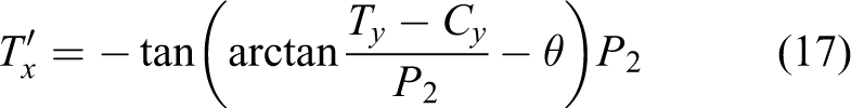
Therefore


The shooting attitude of camera when pitch angle is not zero.
Target positioning under world coordinate system
In actual tracking process, the target location under world coordinate system always can’t be achieved only through the above calibration, the height to the ground is also needed to be taken into consideration. Assume the height achieved from GPS is h, and it is easy to obtain the target displacement vector

In order to verify the effectiveness of the proposed positioning algorithm, a positioning experiment was accomplished on our UAV visual platform. Because the positioning system and vision system can work separately, we manually controlled the height and gesture angles in this experiment and kept the ground robot moving in the visible area of the camera. The results of the experiment are shown in Figure 9. From the comparison of the set-point value and the actual measurement value, it can be concluded that the positioning results can satisfy the tracking requirements.

The experimental results of target positioning algorithm.
Semi-physical simulation platform configuration and experiments
In this section, we set up the hardware-in-loop platform of Qball-X4 UAV to verify the tracking and positioning algorithm that we proposed in the earlier section.
Semi-physical simulation platform
The whole control system has been divided into three parts during the platform set up process in order to enhance its readability. The three parts are the target positioning and communication module, the target tracking module and the Qball-X4 hardware drive module, respectively. In addition, each of the main modules has several submodules with different functions. The design process of the target tracking module including PID controller and Kalman filter has already been introduced in the study by Pan et al. 18
The target positioning and communication module is mainly consisted of two parts, namely the target tracking and positioning program and the communication module. Because the target tracking and positioning algorithm proposed here is rather complicated and requires a great amount of operation, the image information has to be transferred back to the ground PC by Wi-Fi instead of processing by the default embedded chip of Qball-X4. Therefore, the tracking and positioning analysis task is achieved by the ground PC and then the obtained target moving information will be transferred back to Qball-X4 UAV. The tracking and positioning program is depicted in Figure 10 according to the algorithm proposed in the last section.

The structure of detecting-tracking-positioning program.
The main function of the communication module is dealing with the communication problem between the ground robot and Qball-X4 UAV and the data transmission problem between M functions and Simulink modules. Simulink is aiming at offline simulation originally; therefore, it can only read from MATLAB workspace before simulation begins and transfers the results back to workspace after simulation is over. This becomes the primary problem in our simulation because the tracking and positioning program is an M function and the flight control system is set up in Simulink, so they can’t communicate online. With the reference of the communication process between the ground PC and Qball-X4, we finally solve this problem by the application of the TCP/IP communication network.
The communication network between the ground robot and Qball-X4 UAV is also achieved through TCP/IP network. In this flight task, if the location information is sent from the ground PC on its own, the set-point value may be already changed before the UAV getting to the target point. This will produce a relatively big tracking error and may even result in driving the UAV away from set-point path because of network congestion. Therefore, in this article, we set Qball-X4 as the stream client and the ground PC as the stream server. The ground PC will constantly send the updated set-point coordinate information to its 18005 port. And when the UAV gets to the current set-point value, it will ask for the coordinate of next set-point from the server. In this way, both of the accuracy problem and the network congestion problem are solved.
Different from pure simulation, the simulation model will be replaced by a real object in semi-physical simulations. Therefore, board drivers are needed to achieve the connection between controller and real object. Figure 11 shows the connector model of the board driver, where ‘HIL Read Write’ is the port which can read and write from the hardware and ‘HIL Set Property’ can achieve parameter settings of the hardware.

Hardware drivers.
Experiment results and analysis
After all the modules were ready, the only thing we have to do to start the experiment was compiling the above introduced modules, downloading them into the Gumstix trip inside Qball-X4 to make Qball-X4 as a QuaRC target and connecting the QuaRC target through Simulink on the ground PC.
The tracking assignment in this article is making the Qbot ground robot move along the Y-axis first, so it will go into the camera’s horizon when it passes the original point, and then it will move to point (1, −1) and go back to the original point along the way it comes. To expand the horizon of the camera, we set the flight height of the UAV as 1 m in consideration of the inside environment. However, because there is a 40-cm distance between the camera and the top of the UAV, the actual flight height will be 40 cm lower than the camera height.
Figure 12 shows the height change during the flight task. From Figure 12, we can see that the camera height was changing between (0.5 cm, 0.7 cm) during the flight. The reason of the fluctuation is that Qball-X4 changes its own gesture during the flight. When it doesn’t maintain a horizontal gesture, the flight height will decline according to mechanical analysis. And when the height is lower than the set point, the output of PID controller will change to get the height back to the set point. In this way, the height of the UAV will fluctuate continuously during the flight. Moreover, the self gesture change of Qball-X4 may also impact the spherical displacer positioning process of OptiTrack, and this may cause a little height error during the flight.

The height change of the camera.
The attitude angle changes of Qball-X4 UAV are shown in Figure 13, in which the set-point value is the output of PID, and the actual value is the actual measured angles got from its self gyroscope. The yaw angle should be kept around zero to prevent any rotation movement of the UAV. The tracking performances of rolling angle and pitch angle are quite satisfactory that they only have about (−0.1 rad, 0.1 rad) error, and these small errors won’t impact the target detecting and tracking results.
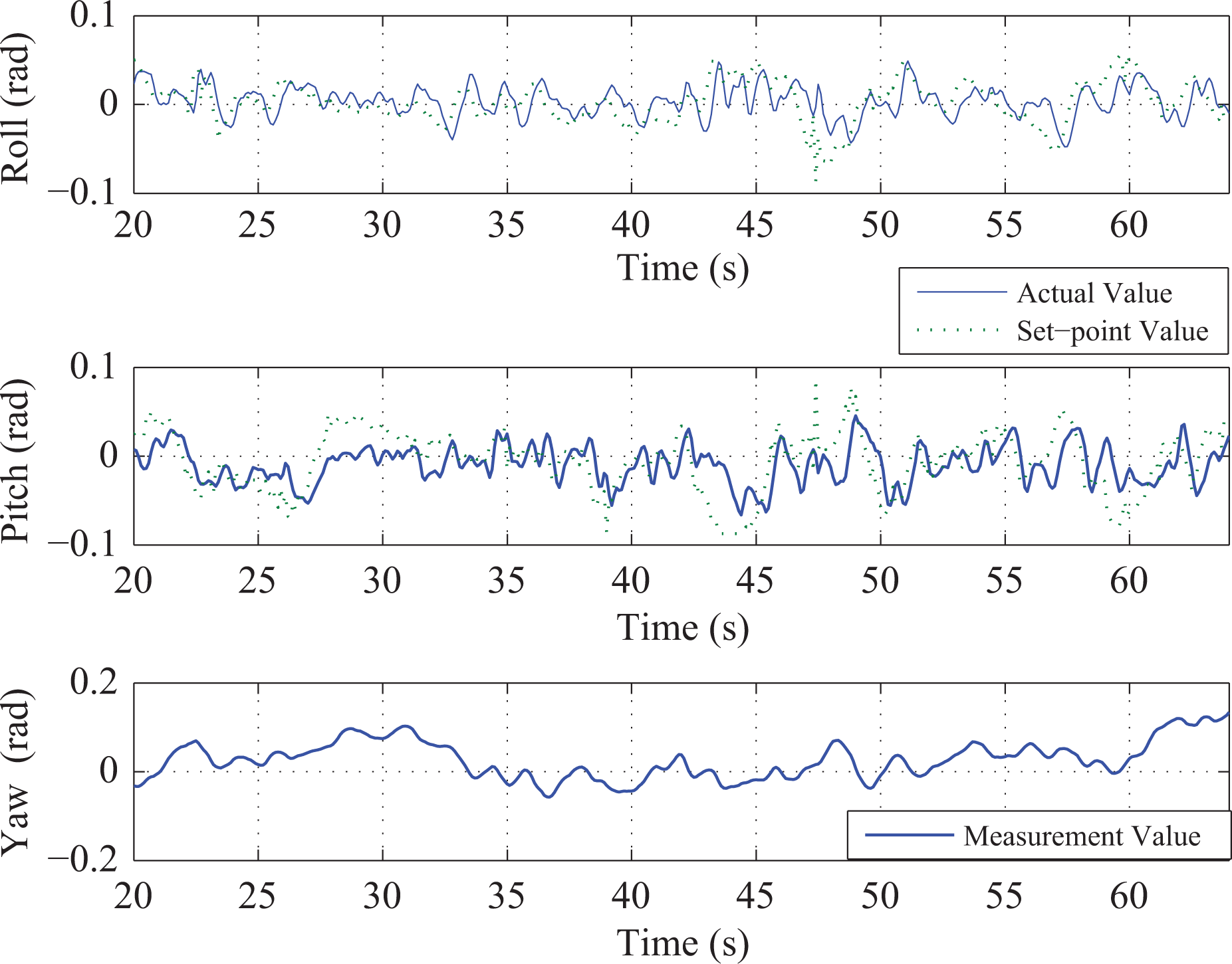
Roll, pitch and raw angles of Qball-X4 UAV. UAV: unmanned aerial vehicle.
Figure 14 presents the Pulse-Width Modulation (PWM) signal changes in the four motors of Qball-X4 UAV. It can be seen that the change trends of the front and the back motors (motor 1 and moter 4) are similar, and the trends of the left and right sides (motor 2 and motor 3) are similar. This is because the pitching angle was controlled by the front and back motors, and the rolling angle was controlled by the left and right motors. The analysis of the PWM signals will help us get a better understanding of the control performance.

PWM signals of four motors.
The position changes in X- and Y-axes in world coordinate are shown in Figures 15 and 16, respectively. In actual tracking process, there are some fluctuations during the flight. But the tracking error is always kept in 5 cm, and this is still in an acceptable range compared to the 70-cm diameter of Qball-X4. Similar to the X-axis, the tracking trajectory on Y-axis is also quite smooth after Kalman filtering. And there is some overshoot when Qball-X4 turns to another direction, but it will return back to the normal tracking trajectory in a short time.

Tracking trajectory on X-axis of Qball-X4.

Tracking trajectory on Y-axis of Qball-X4.
The tracking and positioning results of the Qbot ground robot are presented in Figure 17. It can be seen from Figure 17 that the tracking performance is quite favourable even there is some minor unsteadiness. The target was missing in the 63rd patch because of some disturbance, but it was recovered and redetected in the 65th patch. Then, the target went out of the horizon of the camera again in the 135th patch, but after the recalculating of the estimated trajectory by Kalman filter, the UAV picked up the target again in a short time. We can conclude from these figures that the proposed tracking and positioning algorithm is qualified to long-time tracking task and is quite robust to target changes. And it can be calculated from the actual moving speed of Qball-X4 that the processing speed of this algorithm is about 10 patches per second, and this can certainly satisfy the control requirements of Qball-X4 UAV.

The tracking result of the Qbot ground robot.
Conclusion
In this article, a tracking and positioning control algorithm is proposed based on Qball-X4 UAV platform. There are mainly four stages in the control strategy aiming at the characteristics of the UAV. The tracking target is first tracked by a tracker based on an optical flow method; then, a cascade target detector is used to help in retrieving the lost target images and improve tracking accuracy; at the same time, the tracking and detecting process is also enhanced by a model updated scheme based on P-N learning system; and at last, the target will be positioned by a monocular visual positioning system based on the corresponding navigation message. The effectiveness of the presented control algorithm is verified both in simulation and several hardware-in-loop flight tasks. Moreover, the proposed control scheme can be applied in various other kinds of tracking systems.
Footnotes
Declaration of conflicting interests
The author(s) declared no potential conflicts of interest with respect to the research, authorship, and/or publication of this article.
Funding
The author(s) disclosed receipt of the following financial support for the research, authorship, and/or publication of this article: This work is supported by the National Natural Science Foundation of China under grants 61174145 and 61673094.