
Abstract
The development of research in robotics in a developing country is a challenging task. Factors such as low research funds, low trust from local companies and the government, and a small number of qualified researchers hinder the development of strong, local research groups. In this article, and as a case of study, we present our research group in robotics at the Advanced Mining Technology Center of the Universidad de Chile, and the way in which we have addressed these challenges. In 2008, we decided to focus our research efforts in mining, which is the main industry in Chile. We observed that this industry has needs in terms of safety, productivity, operational continuity, and environmental care. All these needs could be addressed with robotics and automation technology. In a first stage, we concentrate ourselves in building capabilities in field robotics, starting with the automation of a commercial vehicle. An important outcome of this project was the earn of the local mining industry confidence. Then, in a second stage started in 2012, we began working with the local mining industry in technological projects. In this article, we describe three of the technological projects that we have developed with industry support: (i) an autonomous vehicle for mining environments without global positioning system coverage; (ii) the inspection of the irrigation flow in heap leach piles using unmanned aerial vehicles and thermal cameras; and (iii) an enhanced vision system for vehicle teleoperation in adverse climatic conditions.
Introduction
Robotics is a research field that involves both science and technology development. As in other fields, carrying out research in robotics in a developing country is a difficult task due to several different factors, mainly: Industry and government support: In several developing countries, the industry and even the government do not trust local research groups for solving their technological problems. They prefer to look for technological solutions in institutions from developed countries. This situation hampers the development of strong, local research groups. Research funds: Research institutions in developing countries have much lower funds for research than their counterparts in developed countries. The main impact of this issue is the difficult for building long-term research groups. Very often, the research is developed only at the universities, with professors as the main researchers and teams composed of undergraduates and/or master students. In this context, it is very difficult to address large or long-term research projects. Availability of qualified researchers: The availability of specialist in specific fields (i.e. robot vision) is very low, which also hinders the development of strong, local research groups. Very often, the specialists in the field emigrate or they do not return to their countries after a PhD or a specialization, because they find better research opportunities in the first world. Distance to research centers and conference venues: The most important research centers are located in developed countries, and the most important conferences also take place in developed countries. A consequence of the long distances from developing countries to these centers is the fact that researchers from developing countries have many difficulties for participating in high-quality conferences and for visiting top research centers. In addition, a consequence of the low density of researchers in the most specific research fields in developing regions is the low quality and impact of the regional conferences in these fields.
All mentioned factors are interrelated, and it seems that we are in the case of a typical chicken-and-egg problem situation. We could ask ourselves, which comes first, financial support, trust from the local industry and government, or the availability of qualified researchers? Obviously, the answer depends on the country characteristics (gross domestic product, specific government programs for R&D, industry’s innovation culture, etc.), on the research field, and on the specific research groups. We will present, as a case of study, our research group in robotics at the Advanced Mining Technology Center (AMTC) of the Universidad de Chile and the way in which we have addressed these challenges.
After being working for about 10 years in service, indoor robotics, with low contact with the Chilean industry, in 2008, we decided to focus our efforts in mining, which is the main industry in our country. We observed that this industry has needs in terms of safety, productivity, operational continuity, and environmental care. All these needs could be addressed with robotics and automation technology. We also saw that most of these challenges were not just local but common to many mining countries such as Australia, Canada, South Africa, and Peru 1 –3 Therefore, we had a perfect application area in which we could have local impact in our country, while at the same time we would be able to solve problems of global relevance. Thus, after obtaining a grant from our government, in 2009, the Universidad de Chile created the AMTC, where we started working in mining automation–related projects. In a first stage, we concentrate ourselves in building capabilities in field robotics, starting with the automation of a commercial vehicle in order to earn the local mining industry confidence showing them our capabilities in the automation of a real-world vehicle. Then, in a second stage started in 2012, we began working with the local mining industry in technological projects.
An interesting aspect to highlight is that we have tackled the lack of qualified researchers in robotics in Chile by training master and PhD students by ourselves. Thus, in our applied research projects, we include graduate students who address the fundamental problems of our research and, at the same time, are trained in real, applied research problems. Also, this allows them to get familiar with the specific needs of the industry.
We think that our research work in the last years has been successful in terms of scientific production and applied research projects. As mentioned, our scientific production is based on the work of master and PhD students, who address the fundamental problems of our research, while engineers address the technological aspects of our projects.
In this article, we present three of our technological projects. In the second section, the development of our autonomous vehicle is presented; in the third section, we describe the inspection of the irrigation flow in heap leach piles using unmanned aerial vehicle (UAVs) and thermal cameras; in the fourth section, we present an enhanced vision system for vehicle teleoperation in adverse climatic conditions; and In the final section, some conclusions of the described research work are drawn.
Autonomous vehicle
We developed an autonomous vehicle with the main goal of creating know-how and technology to be applied in autonomous navigation inside mining environments with poor or absent global positioning system (GPS) coverage. (Most of the autonomous vehicle initiatives are based on the use of GPS. 4 –7 ) For instance, in open-pit mines, typical truck speeds are in the range of 5–14 m/s and navigation based on pure GPS is not reliable, because in some deep sections of the pit, GPS signal is not always available. Therefore, robust terrain mapping systems are of high interest. Our secondary goal was to have a development platform where we can train engineering and graduate students in field robotics and vehicle automation. Taking into account that we wanted to develop know-how in vehicle automation, we decided to take a commercial vehicle and to automate it from scratch, including the instrumentation and sensing aspects, such as controller area network (CAN) bus communication, actuation of the steering wheel, and so on.
Our autonomous vehicle corresponds to a standard Volkswagen Tiguan 2010 (see Figure 1). The roof rack has aluminum-extruded profiles installed for mounting sensors. The vehicle parameters are presented in Table 1. A list of installed sensors is presented in Table 2. The original Tiguan vehicle was mechanically and electronically modified in order to make it autonomous. The modifications can be outlined as follows: the steering wheel is actuated by a brushless motor connected by a chain to the steering column, therefore, both rotate synchronously. The brake pedal is pulled by a steel rope, which is moved by a linear actuator, placed on the copilot’s footrest. The control hardware of the accelerator pedal and parking brake was modified, therefore, both devices are electronically controlled. The vehicle’s internal sensors data is directly acquired from the CAN bus interface. A rack with electronic controllers and computers was installed in the vehicle’s trunk. The data acquisition and control routines run on an automotive standard Intel i7 610E @2.53 GHz (4 GB RAM) computer, running ROS-Indigo on Ubuntu 14.04, Advantech, ARK-3440. More details on the control modules used in this vehicle can be found in the literature. 8,9
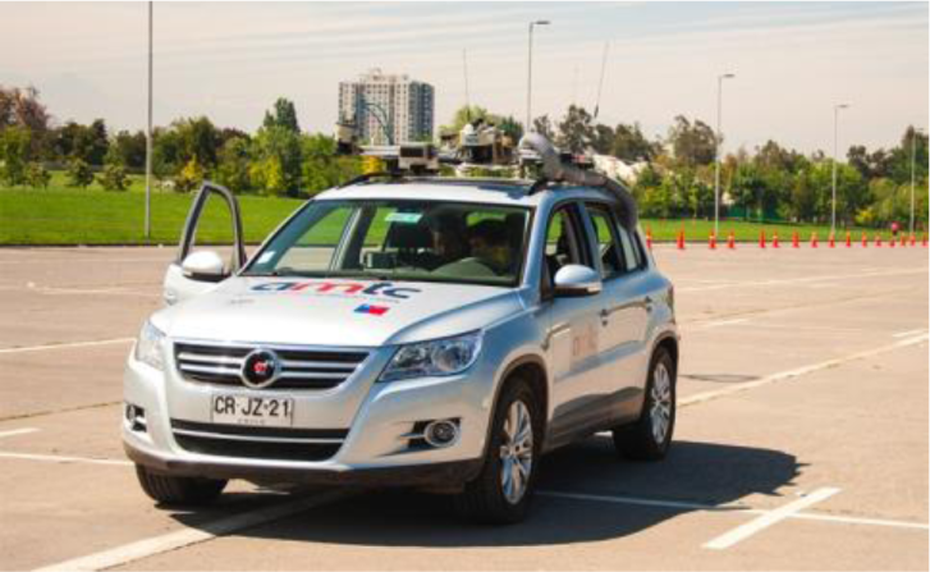
AMTC’s autonomous vehicle. AMTC: advanced mining technology.
Vehicle model parameters (Volkswagen®Tiguan).

AMTC’s autonomous vehicle sensors.

AMTC: advanced mining technology; CAN: controller area network; LIDAR: light detection and ranging; RADAR: radio detection and ranging.
Some of the main methods and algorithms that have been developed using this autonomous vehicle are as follows: An adaptive and real-time visual road segmentation method for off-road autonomous driving
8
: The method is based on the use of adaptive color histograms; however, its main novelties are the use of the random sample consensus algorithm
10
in order to determine the road borders and the vanishing point and a set of heuristic rules that allow checking the spatiotemporal consistency of the road determination. A Kalman-filtering-based approach for improving terrain mapping in off-road autonomous driving applications
9
: The proposed methodology uses an extended Kalman filter
11
to estimate in real time the instantaneous pose of the vehicle and the laser range finders by considering measurements acquired from an inertial measurement unit, internal sensorial data of the vehicle, and the estimated heights of the four wheels, which are obtained from the terrain map, and allow determination of the vehicle’s inclination. The estimated 6D pose of the laser range finders is used to correctly project the laser measurements onto the terrain map. The terrain map is a 2.5-D map that stores in each cell the mean value and variance of the terrain height. In each map’s cell position, new laser observations are fused with existing height estimations using a Kalman filter. Figure 2 shows the height estimation accuracy measured for the proposed methodology; it can be observed an error of less than 0.1 m for the 70% of the cells. A traversability mapping methodology for off-road autonomous driving applications
12
: The methodology fuses visual information (the segmented road) and the map of the terrain in order to determine a local traversability map that is used by the vehicle for determining its path. The fusion is implemented using a bank of Gabor filters, based on the ideas proposed in the study by Hoffman and Krotkov.
13
A semantic mapping methodology for large-scale outdoor scenes in autonomous off-road driving applications
14
: The semantic map representation consists of a large-scale topological map built using semantic image information. Thus, the proposed representation aims to solve the large-scale outdoors semantic mapping problem using a graph-based topological map, where relevant information for autonomous driving is added using semantic information from the image description. A fuzzy longitudinal controller of the speed of an autonomous vehicle
15
: Taking into account the complexity of vehicle dynamics, the vehicle perturbations, the variability of a theoretical model parameters, and the available knowledge of a human driver about vehicle speed, a fuzzy longitudinal controller of the vehicle speed was proposed.

Percentage of cells whose root mean square error is lower than a given threshold.
Having an autonomous vehicle that can be shown to industry partners allowed us to get their trust and then to start developing projects with them. For instance, a direct application of this project is an autonomous navigation system for load–haul–dump (LHD) machines, which we are developing together with the German original equipment manufacturer (OEM) GHH Fahrzeuge. This system is described in subsection “An autonomous navigation system for LHDs operating in underground mines.”
An autonomous navigation system for LHDs operating in underground mines
The goal of this research is to allow LHD loaders to navigate autonomously in underground mine tunnels. These loaders are used to load, haul, and dump minerals inside mines (see Figure 3). In order to navigate autonomously inside the tunnels, the control system uses a reactive local navigation (or guidance) scheme, based on a mix of optimal and predictive control. A path is generated by minimizing a cost function that uses the LHD’s kinematic model. This cost function includes factors such as distance to the walls along the path, speed of the vehicle, and the actuators’ effort, achieving smooth and natural movements. The global path planning uses topological modeling and Dijkstra’s algorithm 16 to calculate the optimal routes. The system also has an emergency collision avoidance module in case the LHD encounters a blocked tunnel.

LHD machine and its main sensors: two LIDAR Sick LMS511 and two cameras Moxa VPort P06HC-1MP-M12. LHD: load–haul–dump; LIDAR: light detection and ranging.
The LHD main sensors are two light detection and rangings (LIDARs), one pointing to the front of the machine and the other pointing to the back. The control systems is organized in different processes that communicate between each other using the robotics-application-oriented middleware ROS.
17
The main functionalities are explained in the next paragraphs. The whole system is described in the study by Ruiz-del-Solar et al.
18
Global path planning and localization: Autonomous navigation is achieved using a global path-planning scheme based on topological mine representation (map) of the mine, composed by two types of nodes: tunnels and intersections. The optimal routes are calculated using Dijkstra’s algorithm.
16
This generates waypoints that allow the trajectory generation module to generate the commands needed by the LHD to navigate from one waypoint to another. In addition, the use of topological map allows obtaining a global localization of the LHD. The position along the tunnels is estimated using the odometry. Reactive local navigation (guidance): The system uses a reactive local navigation (or guidance) scheme, based on a mix of optimal and predictive control. The module receives input from the global path planning to reach a desired goal. A sequence of commands is generated by minimizing a cost function that uses the LHD’s kinematic model,
19
the distance to the walls along the path, the speed of the vehicle, and the actuators’ effort, achieving smooth and natural movements. Collision avoidance: This module detects incoming obstacles and overrides the system commands in order to avoid collisions. An obstacle tracking system minimizes the amount of false-positive detections without compromising security.
In order to facilitate the software development and testing, an LHD navigation simulator, based on Gazebo 2, 20 was developed. The simulator was designed to simulate the LHD navigation, focusing in the interaction between the LHD actuators and the environment. The simulator is based on the LHD model LF11H from GHH, 21 using its physical dimensions for the LHD simulated model. The simulated LHD model uses the bounding box of the LF11H for both the collisions model and the visual representation. In this way, the computation load of the simulator is reduced. The simulated LHD has an articulation with cylinders; it is controlled through the cylinders’ forces. In the case of the traction, the controlled variable is also the force, simulating the axles’ differentials as well. All the relevant sensors are simulated. Front and rear cameras generate synthetic images and front and rear laser scanners generate their respective readings. All simulated sensors include a model of the response including the sensor noise. Also, a speedometer and an articulation encoder give information about the simulated LHD kinematic state.
An experimental evaluation of the control modules using the simulator was carried out. The maximum latency observed between the sensors’ reading and the output command of the system was 150 ms. The path-planning algorithm was tested in a large mine scenario with eight parallel streets with 19 intersections each one (a total of 256 draw points and 16 dumping points) (see explanation in the study by Ruiz-del-Solar et al. 18 ). Under these conditions, the path planning took less than 15 ms for all simulated cases. The system solved successfully in all the cases of the inversion of the LHD movement (LHDs moves forward and backwards). The reactive local navigation (guidance) successfully drove the machine in tunnels with a width of 1 m over the LHD’s width. Under these conditions, the speed achieved in straight tunnels is 5 m/s, limited by the machine simulation parameters, not the software.
Currently, the system is being installed in an LF11H LHD. All the automation software is being installed in an industrial fanless computer with an Intel i7 processor, with eight logical cores. The interface between the automation and the machine is being programmed by GHH in the machine controller. The factory validation is going to be performed in a test field close to GHH facilities in Santiago (Chile) between August and November 2016.
The final validation of the system will be carried out in a real sublevel stopping mine (San Gerónimo Mine, Coquimbo Region, Chile). In this industrial validation, the system will be tested incrementally from one shift operation to full 24/7 operations. This industrial validation will be carried out during 3 months. During the industrial validation, the performance of the system will be compared to the one of manual operation.
Inspecting the irrigation flow in heap leach piles by UAVs with thermal cameras
Problem description
Heap leaching is a mineral process in which crushed or run-of-mine rock is leached with chemical solutions in order to extract valuable minerals. Heap leaching technology is largely applied to copper-containing minerals in which these are irrigated with a weak sulfuric acid solution. This solution dissolves the copper from the mineral and the “pregnant leach solution” (PLS) passes down through the ore pile and is recovered at the bottom. The bottom of the leach pile is usually constructed with a geo-membrane liner and a permeable crushed rock drainage system along with a drainage pipe network (see picture of a leach pile in Figure 4). Copper is extracted from the PLS using electrowinning processes and the acidic solution is recycled back onto the leach pile. The critical aspects of heap leach piles can be summarized as the depth of the ore, and the equipment loads for on/off pads, presence of water and local terrain. 22 All these variables can dramatically affect the piles’ stability. Since the piles may become locally saturated from leach solution irrigation, the potential for liquefaction also exists and is often considered, especially when the pile is located in a seismically active zone. However, liquefaction flow slide failures have also been reported to occur under static conditions; these are of particular interest because of their catastrophic consequences over the operations, and of course, the life of the human operators that work in the surroundings, helping the management and maintenance of the heap leach pile.
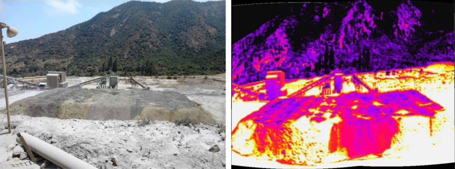
Picture of a real leach pile (Left) and thermal image of the same pile (Right).
Therefore, to inspect the irrigation of the pile is relevant in order to avoid saturation zones, which can compromise, besides the leaching process, the stability of the pile. The inspection is also relevant to recognize the zones that are not irrigated, in order to improve the leaching process as well; as the saturation zones are detected, suitable control actions in the irrigation system can be performed. In such case, in those zones in which there is an excess of solution, the corresponding valves should be closed, yet in those zones there’s a lack of solution, the flux must be increased. If these issues are controlled, the leaching rate will be increased, which is traduced in an increase of recuperation of copper from the pile, and so its production.
Given that the inspection of large piles is a complex process, which is normally carried out manually, the automated inspection of the piles increases safety, especially for the operators that work in the management of the pile. In order to address this issue, we proposed a monitoring system that uses a UAV equipped with a thermal camera. The objective is to detect the saturation zones and the nonirrigated zones by thermal analysis, which can be conducted by processing the thermal images and correlating the temperature of the pile with its irrigation.
Methodology
The project uses data from a heap leach pile in El Soldado Mine from Anglo American. The dimensions of the pile are L 48.4 × W 24.4 × H 2.5 m. The distance between two rows of irrigation lines is 3 m. The thermal images were acquired using a FLIR 320 TAU Thermal Camera, 9 mm-f1.25, FLIR, with sensitivity in the range of 7.5–13.5 μm and a resolution of 324 × 256 pixels mounted in a UAV. The UAV is a hexarotor built by us (see Figure 5), whose main characteristics are shown in Table 3.

Picture of the AMTC’s hexarotor. AMTC: advanced mining technology.
AMTC’s hexarotor main components.

AMTC: advanced mining technology.
In order to inspect appropriately the pile, three classes are defined using the different zones of the irrigation inside the heap leach pile: saturated zone, irrigated zone, and dry zone. Using images that were obtained from the thermal camera, two sets of images are generated. The first set is for training, while the second set is used for evaluation. From the training set images, image pixels for each class were labeled. These data were used to calculate histograms for each class. Then, given the data distribution in the histograms, a Gaussian model is estimated for each class. Naive Bayes (Naive Bayes is a robust classifier based upon the principle of maximum a posteriori.) is used to estimate the class of each pixel. 23 The details of the implementation are explained in the study by Ruiz-del-Solar et al. 24 Examples of the segmented images are shown in Figure 6.
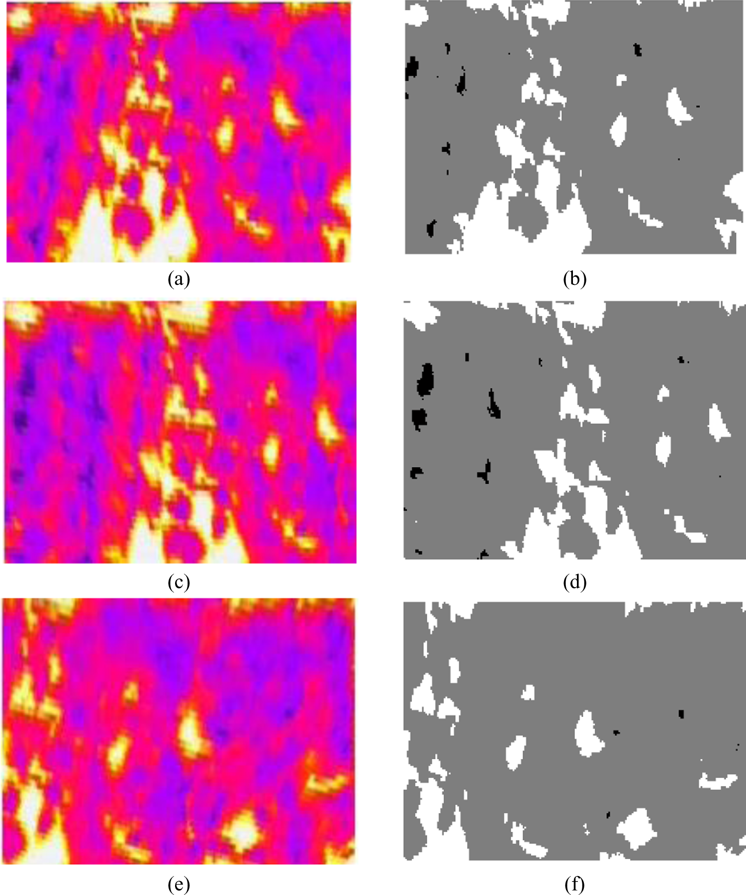
Some examples of the image segmentation. (a), (c), and (e) thermal images, in which deep blue zones are the saturated areas, while white zones correspond to dry areas inside the heap leach pile. (b), (d), and (f) the segmented images.
After an analysis of the obtained results, it was clear that the segmentation of the thermal images was successfully conducted, giving solid information about the classified zones. Thus, using thermal image processing, it is possible to distinct between saturated, dry, and zones that are irrigated in a proper way. Moreover, as the irrigation system follows an irrigation line, the system can be connected to the irrigation valves’ control such as programmable logic controller (PLC) to automatically control the irrigation. Herein, if a saturation zone is detected through thermography, the PLC is fed with this information in order to compute a correcting action, that is, the corresponding valves should be closed, until the saturation is gone. In the opposite case, in which some zones of the pile are dry, the irrigation control system must send a higher flow and/or to more open the valve in order to increase the flux.
As the excess of humidity can seriously put in danger the stability of the heap leach pile, raising exponentially the risk of collapse because of liquefaction, such monitoring system helps maintaining the stability of the pile. This leads to an increase of safety in the leaching process, as no human operator needs to be in the immediate surroundings, where these collapses can injure or put in danger the life of the operator.
A comparison between using the thermal camera mounted in the UAV or in towers surrounding the leach pile was made. Table 4 shows the area coverage of a pixel in both cases for different mounting heights in the case of tower and flying heights in the case of UAV. It can be seen that for the analysed cases, the resolution of the UAV mounted camera is higher than the tower mounted camera in all cases. Also, for the analyzed cases, the resolution of the UAV mounted camera is higher than the tower mounted camera in all cases.
Comparison of area coverage per pixel between a tower mounted camera and a UAV mounted camera.a
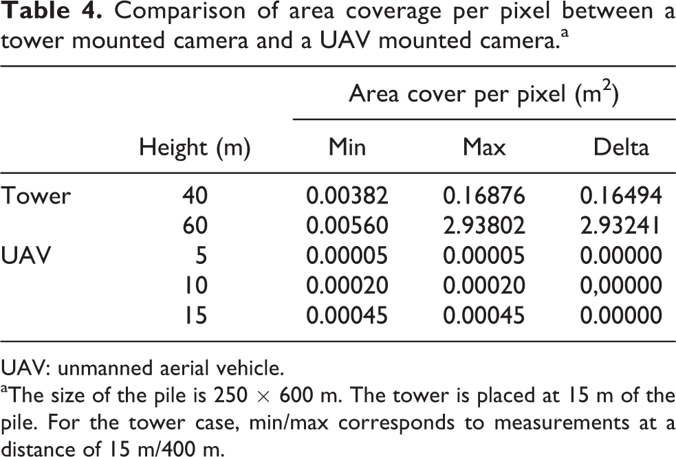
UAV: unmanned aerial vehicle.
aThe size of the pile is 250 × 600 m. The tower is placed at 15 m of the pile. For the tower case, min/max corresponds to measurements at a distance of 15 m/400 m.
Enhanced vision system for vehicle teleoperation in adverse climatic conditions
Problem description
As in many open-pit mines located at an altitude higher than 3000 m in the Chilean Andes (e.g. Collahuasi mine, Pascua Lama mine, and Los Bronces mine), open-pit operation in CODELCO’s Andina Division (Corporación Nacional del Cobre (CODELCO)) is a Chilean state–owned mining company. It is currently the largest copper-producing company in the world) is interrupted in the presence of adverse climatic conditions, namely, snow falls, in the winter season. Specifically, when snowfall is over the 4 cm/h threshold, the climate condition is considered adverse, and all manual operations are stopped due to the high level of risk that operators would be exposed to. In order to address this issue, the CODELCO’s project “Application of Autonomous Mining in Open Pit Operations, Stage I” is currently under development. This project aims to teleoperate a team of mining vehicles, thus providing them with the technology needed to operate remotely in adverse climatic conditions. By this means, mine operating time is increased and operators risk exposure is decreased. Afterward, this technology will be available to be adapted for other CODELCO divisions.
Mining vehicles will be operated from a remote and safe location. Therefore, it is essential for the teleoperator to have as much as possible information about the operating environment.
In the framework of this project, an enhanced vision system for vehicle teleoperation in adverse climatic conditions was developed by our robotics group. 25 This system involves the fusion of information from different sensors to provide an enhanced vision system for teleoperators. The components of the system are a visible spectrum camera, a far infrared spectrum (thermal) camera, a radio detection and ranging (RADAR), and a LIDAR. Together, these sensors allow the detection of obstacles and provide the teleoperator with visual feedback fused with additional distance-to-obstacles information (see Figure 7).

(a) Integrated sensor: (top left) standard Charged Coupled Device (CCD) camera; (top right) thermal camera; (bottom left) LIDAR; (bottom right) ADAR. (b) Fused images that integrate the data of all four sensors. LIDAR: light detection and ranging; RADAR: radio detection and ranging.
Methodology
First, images are acquired from the cameras. These images are rectified in order to correct the geometric distortion introduced by the cameras’ lenses. Due to their nature, thermal images have much more noise than visible images. This noise is handled by low-pass filtering the thermal images. Then, thermal and visible images are aligned, making both images to match the same point and field of view. At this point, both images are fused, emphasizing pixels in the visible image in the positions where thermal images have high contrast while visible images have low contrast.
Finally, three new visualizations are obtained from a tridimensional reconstruction. The tridimensional reconstruction is performed using OpenGL libraries. This OpenGL implementation allows taking advantage of the hardware acceleration provided by the graphic card in the reconstruction and visualization processing. The elements drawn in the reconstruction are the following: Ground plane. A plane drawn parallel to the ground (z = 0 in the vehicle coordinate system). The vehicle coordinate system is defined with the origin in the projection of the vehicle's center to the ground, with the X axis pointing forward, the Y axis pointing to the left of the vehicle, and the Z axis pointing up.
Far distance plane: A plane drawn in front of the vehicle at a far distance (x = far_distance in the vehicle coordinate system), this plane is used for the background plotting.
Distance reference circles: Circles drawn in the ground plane centered in the vehicle with increasing radiuses.
Thermal and visible fused image: The image obtained from the thermal and visible fusion is projected over the ground and the far distance planes. Georeferenced map: Tracks stored in a georeferenced map are drawn over the ground plane. For an appropriated plotting, the position and attitude obtained from an inertial navigation system is used.
Range sensors detections: Detections coming from the LIDAR and from the RADAR are processed for noise reduction and segmentation. Then, fixed height fences are drawn surrounding the segmented detections.
The three visualizations are as follows:
First-person view
Third-person view: Visualization with the viewpoint in 45° up and behind the vehicle. The thermal and visible fused image is not drawn in this visualization (see Figure 7(b) bottom left).
Bird eye view: Visualization with the viewpoint from far over the vehicle. The thermal and visible fused image is not drawn in this visualization (see Figure 7(b) top right).
In snowfall conditions, the contribution of the LIDAR, RADAR, and thermal camera to the visualization was compared to the visible camera in terms of sensing range. Thus, Figure 8 shows the range of each sensor as a function of the visible camera range, polynomial tendency lines were added to each sensor graph. It can be seen that only RADAR exceeds the visible camera range in reduced visibility.
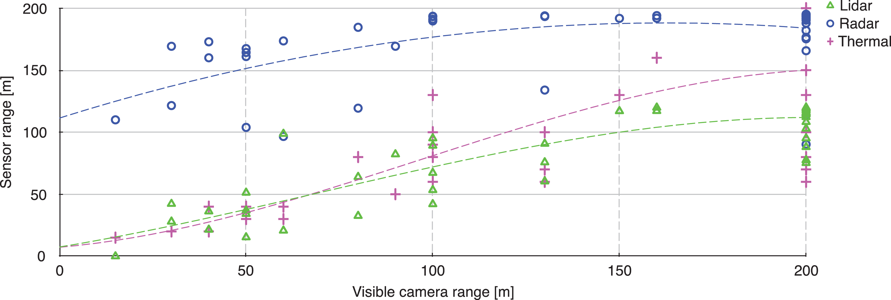
Sensing range of the LIDAR, RADAR, and thermal camera compared to the range of the visible camera affected by snowfall. LIDAR: light detection and ranging; RADAR: radio detection and ranging.
Conclusions
In this article, we have described how our research group in robotics at the AMTC of the Universidad de Chile has addressed the challenge of developing world-class research on robotics.
A key element was the decision of focusing our research efforts in mining, which is the main industry in Chile. Given the fact that the Chilean mining industry has needs in terms of safety, productivity, operational continuity, and environmental care, which are common to many mining countries, focusing our research in this application area allowed us to have local impact in our country, while at the same time we would be able to solve problems of global relevance.
In a first stage, we concentrate ourselves in building capabilities in field robotics, starting with the automation of a commercial vehicle, which allowed us to earn the local mining industry confidence. This project and its main research results are described in the second section.
Then, in a second stage started in 2012, we began working with the local mining industry in technological projects. In this article, we described two of the technological projects that we have developed with industry support: the inspection of the irrigation flow in heap leach piles using UAVs and thermal cameras and an enhanced vision system for vehicle teleoperation in adverse climatic conditions.
Two of our current most interesting technological projects are (i) a semiautonomous navigation system for LHD machines, which we are developing together with the German OEM GHH Fahrzeuge and (ii) the development of interoperability standards for teleoperated and autonomous machines, which we are developing together with CODELCO, the largest Chilean mining company. Both projects are fully supported with industry funds.
A last aspect to be highlighted is that we have tackled the lack of qualified researchers in robotics in Chile by training master and PhD students by ourselves. Thus, in our applied research projects, we include graduate students who address the fundamental problems of our research and, at the same time, are trained in real, applied research problems. Also, this allows them to get familiar with the specific needs of the industry.
Footnotes
Declaration of conflicting interests
The author(s) declared no potential conflicts of interest with respect to the research, authorship, and/or publication of this article.
Funding
The author(s) disclosed receipt of the following financial support for the research, authorship and/or publication of this article: This work was partially funded by FONDECYT (CHILE) Grant 1161500, and by GIZ (Germany) Grant “Accesible automation for a more efficient and safer underground mining in Chile.”