
Abstract
The quadrotor has been the most popular aircraft in the last decade due to its excellent dynamics and continues to attract ever-increasing research interest. Delivering a quadrotor from a large fixed-wing aircraft is a promising application of quadrotors. In such an application, the quadrotor needs to switch from a highly unstable status, featured as large initial states, to a safe and stable flight status. This is the so-called large-scale stability control problem. In such an extreme scenario, the quadrotor is at risk of actuator saturation. This can cause the controller to update incorrectly and lead the quadrotor to spiral and crash. In this article, to safely control the quadrotor in such scenarios, the control input constraint is analyzed. The key states of a quadrotor dynamic model are selected, and a two-dimensional dynamic model is extracted based on a symmetrical body configuration. A generalized point-wise min-norm nonlinear control method is proposed based on the Lyapunov function, and large-scale stability control is hence achieved. An enhanced point-wise, min-norm control is further provided to improve the attitude control performance, with altitude performance degenerating slightly. Simulation results showed that the proposed control methods can stabilize the input-constrained quadrotor and the enhanced method can improve the performance of the quadrotor in critical states.
Introduction
Hailed for its marvelous dynamical capabilities, the quadrotor has proved to be a reliable tool in a wide array of applications such as surveillance, transportation, aerial photography, and disaster response. The near-hovering control of the quadrotor has been extensively studied by many researchers from various perspectives. 1 –3 However, problems arise in considering the potential application of delivering a quadrotor from a fixed-wing aircraft, as stabilizing a quadrotor with “large initial states” is a challenging issue. The combination of a quadrotor and a fixed-wing aircraft can meet the requirement of a fast response to emergencies in low airspace or on ground by exploiting the advantages of two types of aircraft and significantly enhancing the quadrotor’s working range. The fixed-wing aircraft excels in flight in the context of large timescales and geographical ranges. However, it cannot maneuver in low airspace at low speed. The quadrotor has a small profile and can carry a variety of payloads. More importantly, it has a simple mechanism (as is depicted in Figure 1) and can be designed to be very portable, which makes it the best candidate in the helicopter family. The fixed-wing plane and the quadrotor are two kinds of aircrafts with significant differences in their flight envelopes, which lead to problems in the scenario being considered. The most obvious problem occurs because the fact that a fixed-wing plane needs to deliver the quadrotor at a certain height at relatively high horizontal speed, and the released quadrotor needs to start up a certain time after it is released to avoid collision with the aircraft. This means that at the very beginning of its control, the quadrotor is already in the so-called large initial states. In such an extreme situation, where the initial velocity of the quadrotor is large and its initial altitude is high, it is difficult for a quadrotor with normal linear controllers to fulfill the task of stabilizing altitude without crashing. This is nontrivial when the quadrotor is restricted to actuation limitation. With a simpler transmission mechanism, the quadrotor is more conducive to the incorporation and implementation of advanced control algorithms to deal with potential problems.

Configuration of the quadrotor.
Although no quadrotor control algorithm available at present can be directly adopted to the above aims, by reviewing past work, crucial aspects of the challenge can be surmised. Early studies on quadrotors mostly focused on dynamic modeling and basic control while hovering. Some research groups investigated the inner loop stability of the quadrotor in the presence of disturbance 4 –8 but did not consider the actuator limitation. With the increasing number of applications of quadrotors, modeling and control aimed at mere equilibrium do not satisfy the need for more difficult maneuvering scenarios, such as acrobat flying, which is drawing increasing attention. In Mellinger et al.’ study, 9 researchers at the General Robotics, Automation, Sensing and Perception (GRASP) laboratory reported their development of an iterative pattern learning method for quadrotors to realize the challenging maneuver of passing through several slots placed at large angles. In each iteration, the controller parameters were updated to generate better control. A similar maneuver was implemented in the study by Mellinger and Kumar 10 using a geometric method. In contrast to Mellinger’s method, Lupashin 11 parameterized the main control values in a flip maneuver and used a learning method to obtain a better control parameter in each loop. As a result, flips, double flips, and triple flips were realized with great precision. The learning algorithm was based on a trial-and-error method, was limited to a known scenario, and therefore is inapplicable to arbitrary situations. To overcome this disadvantage, researchers at the GRASP laboratory 10 developed an algorithm that allows real-time generation of optimal trajectories through a sequence of three-dimensional positions and yaw angles. Constraints on velocity, acceleration, and the inputs of the quadrotor were considered in planning the trajectory to render it traceable. Similarly, Hehn et al. 12 used the bang–bang control algorithm to develop a temporally optimal state-to-state control algorithm. A two-dimensional (2-D) first principles model was deduced to simplify the problem, and the time-optimal trajectory was calculated using a search method in 2-D space. Only a few studies discuss the large initial states problem. Wang and Su 13 designed a switch control algorithm for problems involving a large initial attitude with external disturbances and internal uncertainties in consideration. Similar studies were carried out by Faessler et al. 14 and Sanchez et al., 15 where controllers successfully stabilized the quadrotor starting from a large initial attitude. However, the outer loop states were not considered. The abovementioned studies are helpful in at least two ways: First, the researchers confirmed the capacity of the quadrotor for aggressive maneuvering. Second, they provided a reliable model of the quadrotor. However, past work does not directly address the application considered in this study. The learning strategies of abovementioned literature can attain high precision in terms of position and altitude control and resist disturbance. However, it should be trained before use, and the application scenarios need to be identical to the training situation. The geometric and optimal methods have other disadvantages as well. For instance, the algorithms used in these methods involve massive amounts of calculation, which is beyond the capability of most controllers for quadrotors.
In our proposed application, the quadrotor is supposed to be dropped from a fixed-wing plane and finally operate at its equilibrium states (namely, zero states). As is well known, the fixed-wing plane has a minimum speed owing to its flying mechanism. Thus, there is a large gap between its large initial states and normal operating states (which is normally the equilibrium state). This article aims at designing a stable control algorithm to safely switch the quadrotor from large initial states to a normal operating state. For this stability control problem, the control input constraint is a key factor that affects the stability of the system. This is because in order to converge to equilibrium from the large initial states, the quadrotor is supposed to generate a large control input. An improper control algorithm incorrectly updates and hence fails to stabilize the quadrotor. This is further explained in Quadrotor actuation constraints. The limitation in the source of actuation needed to attain these two goals leaves us with the question: What is the appropriate choice of control to exercise within the control constraint to satisfy both aims? The chosen strategy needs to be simple in terms of the calculation required so that it can be implemented in a quadrotor controller. As constraints incur nonlinear characteristics, which invariably imply large amounts of calculation and no analyze solution, the ideal method for this scenario would operate offline in order to deal with such complex constraints as the learning strategy. It would also need to use a simple strategy to stabilize the system, which is acceptable for normal quadrotors on board chips.
He and Han 16 proposed a control-Lyapunov function for robust control as well as a generalized point-wise min-norm control that can handle inputs and outputs in nonlinear systems with constraints. This article adopts this algorithm and improves it to fit quadrotor dynamics and its actuation constraint. The control-Lyapunov function is a method to design controllers for nonlinear systems using the Lyapunov function. Compared with the robust controller design of the traditional Lyapunov function, it omits the “guess-trial” process. It is also known as the direct Lyapunov function robust control method. By introducing the control-Lyapunov function, the constraints on the controller can be analyzed offline, in contrast to the original design. By dealing with the problem offline, massive calculations online are avoided, and only simple control calculations are conducted to generate a guiding control output. This method features various combinations of the control algorithm providing diverse control targets such as stabilization and tracking.
The remainder of this article is organized as follows: In section “Quadrotor actuation constraint and dynamics,” the actuation constraint of the quadrotor is discussed and the dynamic model of the quadrotor in two key dimensions is introduced. Section “Controller design” introduces the method of generalized point-wise min-norm control and describes its adaptation to quadrotor dynamics. An augmented method is also provided here. In section “Simulation,” we describe two simulations to test our methods. The first simulation highlighted the problem facing with a linear controller and showed how the proposed controller can address the control constraint barrier. The second showed that the proposed augmented algorithm betters off in attitude control. We discuss potential avenues for future work in section “Conclusion.”
Quadrotor actuation constraint and dynamics
As it is an important factor in the stabilization problem, we discuss the form of the actuation constraint. A simplified dynamic of the quadrotor with two degrees of freedoms is established, and usage conventions for the entire article are provided in this section.
Quadrotor actuation constraints
A convention should be confirmed before the dynamics are analyzed. As shown in Figure 2, the north-east-down frame is chosen as the reference coordinate fixed on the ground at point oe from where the quadrotor is assumed to take off. A body frame obxbybzb is attached to the quadrotor with origin coincident with the center of gravity of the quadrotor. For the sake of simplicity of coupling in actuators, the arrangement of the frame is chosen in the “+” manner. Unit vector obxb points to the head of the quadrotor, obyb points to the right of the quadrotor, and obzb points downward.

Convention of the coordinates.
The constraint on the quadrotor is an important factor in this article. The generalized forces acting on the quadrotor are the original forces and torques generated by the propellers. However, in the controller design, the control input is to be in accordance with the freedoms established in the dynamic equation. Hence, the map from the original forces and torques to the control outputs should be examined.
For a single actuator, the limitation on the rate of rotation is Ω lmt. Thus, the actuator works in the following zone: 0 ≤ Ωi ≤ Ω lmt. The relationship between the generalized forces and the propellers’ rates is depicted by equation (1). By applying the map from the ration rates to the generalized forces, the actuation zone is obtained, as shown in Figure 3. For now, we analyze the T-M 1 space, considering that the quadrotor is highly symmetric and this space is representative. T total stands for the total thrust of the two actuators and M max is the maximum torque. Figure 3 shows the conversion from the actuation constraint zone


Actuation constraint of a 2-D quadrotor model. 2-D: two-dimensional.
In this article, we use simplified quadrotor dynamics. There are three reasons for the choice of this model. First, the quadrotor is highly symmetrical in terms of configuration and dynamics. In our application, the trajectory of the dropped quadrotor is mainly in the xoz plane. By quickly adjusting the quadrotor’s attitude (this is simple because the attitude loop is in full actuation and the timescale is much smaller than in the problem discussed here), the dynamics is representative in a vertical plane; we call it the xoz plane. Second, the dropping zone is supposed to be flat and vast, which is common. Hence, of all states, horizontal freedom is far less important than that along the other two axes, namely the vertical axis and the pitch. Third, the dynamics of the actuator are neglected because actuator dynamics involve small time delays and are assumed to be instantaneous in the problem at hand

where z is the vertical position, θ is the pitch angle, g stands for gravitational acceleration, Δ1 is the disturbance in vertical freedom, and Δ2 is the disturbance in pitch freedom. T stands for thrust, M for torque, and Iyy is the inertia about the x-axis.
The actuator constraint of the quadrotor also explains a special phenomenon: when a large vertical error is imposed on the quadrotor, the controller generates a large collective force. If the force is greater than T total, the actual force input is T total. As can be seen from the constraint, torque is zero; this causes the quadrotor to spiral and crash.
Controller design
In this section, we provide two algorithms. First, a nonlinear controller based on generalized point-wise min-norm control is designed. The main objective of this controller is to coordinate the inner and outer outputs of the quadrotor controller, so that the full states of the quadrotor are stabilized through actuation limitation. Second, to improve the performance of the quadrotor at high altitude, an augmented point-wise min-norm control is designed. The proposed algorithm functions better in situations where attitude control is more critical than vertical control.
Generalized point-wise min-norm control
The proposed algorithm is based on the concept of the control-Lyapunov function. 16 It can be stated as follows:
For an autonomous dynamical system

where x∊R stands for the states of the system, u∊R is the control input for the system; we want to feedback stabilize it to x = 0 in some domain D∊R.
A control-Lyapunov function is a continuously differentiable, positive-definite function V: D→R, and such that: ∀x ≠ 0, ∃u

Furthermore, the Lyapunov function V(x) is a local robust control-Lyapunov function for system , such that

Consider the nonlinear system of the form

where x stands for the states of the system, y∊Rt is the output of the system, u∊Rt is the control input for the system, u∊Rp is an uncertain parameter of the system, Δ∊Rr is the external disturbance acting on the system, and f, g, q, and h are smooth functions with corresponding dimensions. U and W(x) are the control set and the disturbance set, respectively. If V(x) is a local robust control-Lyapunov function, and U(x) and W(x) satisfy the following conditions:
Uncertain constraint W(x) is continuous set-valued mapping, x∊Dc
1/Dc
2, and
U(x) is a lower, semi-continuous, convex set-valued enclosed mapping.
ξ(x) is a continuous function of quadrotor state x.
The following conclusion can be drawn:
There exists a positive continuous function a(x) such that equation holds
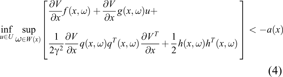
The following controller (generalized point-wise min-norm control of affine nonlinear controller)

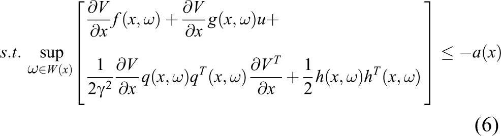
makes the system from disturbance to output L 2 stable with gain less than γ.
ξ is a continuous function of quadrotor state x, and u∊KV
satisfies the following conditions:
Where


The generalized point-wise min-norm control is a robust control method aimed at nonlinear systems with control constraints. It can deal with bounded uncertainty and is more flexible in design for various performance requirements.
Quadrotor controller based on generalized point-wise min-norm control
The design of the generalized point-wise min-norm controller expressed by equation for the quadrotor can be separated into three main parts. First, KV (x) should be solved given the form of restraint on the quadrotor. Second, the guiding function ξ(x) is built. Third, to complete the design, the solution of equation should be calculated.
1. KV (x) is defined in section “Generalized point-wise min-norm control.”

Kv is shown in Figure 3 and redrawn in Figure 4, which is enclosed by four line segments—l 1, l 2, l 3, and l 4—with point group Pc : Pc 1, Pc 2, Pc 3, and Pc 4 as the end points of the line segments, respectively. U(x) is defined by the actuation constraint, which is analyzed in section “Quadrotor Actuation Constraint and Dynamics.” As stated in section “Generalized point-wise min-norm control,” Lv (x) is the actuation zone that guarantees the stability of the system without considering the input constraint. It is calculated based on the Lyapunov function and eventually depends on the states of the system. The Lyapunov function is a scalar function of the states of the system; in our set, it is the sum of the squares of states of the equivalent state equation. To calculate Lv (x), we need to obtain the control-Lyapunov function. This is done through the feedback linearization method proposed in the study by Jiang et al. 17
2. Based on the linearized system, we design a linear controller ξ(x) = Ke as the guiding function, where e = xd−x, x = [x 1, x 2, x 3, x 4], xd = [x 1d , x 2d , x 3d , x 4d ].

Control input.
This strategy is used because the feedback linearization technology converts the nonlinear system into a virtual linear system, and the input of the virtual linear system is noted as vector v with components v
1and v
2, the virtual collective force input and the virtual torque input in the virtual linear system, respectively. The linear controller design technique can thus be implemented to calculate v. When the linear virtual control inputs are calculated, the real control input u is composed of actual collective force T
total and torque M
1 and can be solved by considering the relationship between u and v:
3. We present the calculation of the analyzed control input solution for two situations depending on the relative position of the guiding function ξ(x) and the polygon, as is shown in Figure 4.
In the first situation, where ξ(x)∊KV (x), control input u can be calculated by equation: u = ξ(x).
Note that βn,l is the angle between vectors n and l. Through simple geometrical analysis, the control input solution is obtained as follows.
For the sake of concise representation, a complete deduction is not given in this article. The details can be found in the work done by Jiang et al. 17

where i in the subscripts represent the number of line sections, l for the left, r stands for the right, and f represents the perpendicular foot of ξ. For example, Pil represents the left end point of line section i. The subscript i is arranged clockwise along the polygon’s contour.
Augmented quadrotor controller based on generalized point-wise min-norm
In the control of a quadrotor, the inner loop control (namely the attitude control) should be given sufficient consideration. This is because attitude is critical to the safety of the quadrotor. It would be plausible to make the best of the torque ability of the quadrotor within the limit of the constraint. In the situation shown in Figure 5, line 0 intersects the convex polygon and leaves a relatively tight horizontal constraint for torque generation. In this subsection, we describe an augmented algorithm that involves deliberately lowering line 0 (the new line section is marked with 0′). The horizontal constraint is therefore enlarged, with stabilization ensured. To maximize the horizontal constraint, line 0′ is supposed to pass through points Pc 4 and Pc 2, which makes it a horizontal line section. For simpler expression of the analytical results, the original line sections 2 and 3 are renamed 1 and 2 here.

Calculation of the actual control input.
There are five positions for line 0 relative to the polygon. The augmented algorithm differs from the original only in the situation shown in Figure 5: namely the line intersects polygon sides 1 and 4. In the other situations, the analytical solution of the control input u of the augmented algorithm remains the same as the original one.
For the sake of concise representation, Figure 6 is divided into two parts by a vertical broken line (that overlaps with the T-axis). The left part is to represent the analyzed resolution of the augmented algorithm, and the right part shows a comparison between the original algorithm and the augmented algorithm in terms of the calculated torque.

The analyzed resolution of the augmented algorithm, and a comparison of the two algorithms.
As in the original algorithm, the choice of actuation input depends on the relative position of the guiding function ξ(x) and the polygon. The left part of Figure 6 is representative and can be used to illustrate the calculation. Note the coordinates of the guiding function in plane T-M (ξx, ξy). The other notations for line sections remain the same as in section “Augmented quadrotor controller based on generalized point-wise min-norm,” with only letter i standing for i′. Pc
2 and Pc
4 are noted as Pc
1 and Pc
2 in this part. The left part of the figure is divided into three subparts by norm vector

The right part shows the advantage of the augmented algorithm over the original one in terms of torque control. As can be easily deduced, the augmented algorithm is superior to the original when the guiding function is in two situations—namely, when the guiding function is in area II and in area III, marked by a slash and a backslash, respectively. When the guiding function is in area II, the result of the original algorithm is Pl
4 and that of the augmented algorithm is Pc
2. The horizontal coordinates of the two points are
Proof of convergence of the augmented algorithm: For the sake of concise representation, we name the polygon enclosed by P
0y
, P
0′y
, Pl
4, and Pc
2 as Kvb
, and name that enclosed by Pc
2, P
0′y
, and P
23 as Kva
. We name the input of the augmented algorithm ua
(x), and it is obverse ua
(x)∊Kva
. The generalized point-wise min-norm control tells that as long as the control input u is within Kv
, the derivative of the Lyapunov function V is smaller than 0. In our set, the Lyapunov function is chosen as the sum of the squares of the states of the equivalent state equation. Hence, if the Lyapunov function is negative along the states’ trajectory, the convergence is guaranteed. Therefore, if we can prove ua
(x)∊Kv
, the convergence of the states can be proven. From Figure. 6, it is easy to draw the conclusion that
Simulation
We ran our simulations on a Dell laptop with a 32-bit CPU with 4 GB of RAM. The code was written in MATLAB installed on the Windows 7 operating system.
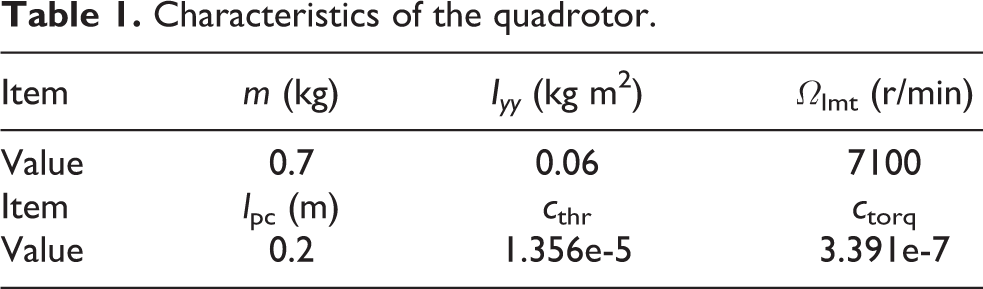
In the two simulations, the model properties were chosen as reasonable values according to common sense. The other properties are given in Table 1.
Characteristics of the quadrotor.
Stabilization using generalized point-wise min-norm control
The generalized point-wise min-norm controller was used to stabilize the quadrotor in this situation. The Lyapunov function V(x) was calculated online, and the feedback coefficient matrix was set as
Through trial and error, matrix P satisfying

where A is the state matrix in the linearized state equation, and Q is a positive-definite matrix.
The stable zone KV (x) was calculated online based on given states x. This ensured the stability of the system. With guiding function ξ(x), the preferred control output was confirmed. In contrast to simulation A, the section line cut off the head of the rhombus when its counterpart in the simulation in A was stuck there.
In Figure 7, the simulation was set up with large initial states. All the states are stabilized. Both vertical position and vertical velocity converged to zero. The maximum error in the position was approximately 8 m; hence, the controller mildly stabilized it. Velocity converged to zero in the way as position did. The inner loop stabilized considerably more quickly than the outer one. Instead of over 2 min, the inner loop stabilized within 20 s.

Vertical stabilization of position and velocity.
Figure 8 shows the evolution of the controller output in the T-M plane. The constraint on the actuator was confined to the rhombus in blue. The group of lines intersecting the rhombus were resolved for LV (x). The guiding control is drawn in the pink circle and the actual control is shown in red line. The control method can stabilize the quadrotor, when the actuators are in saturation. This controller is much better than a linear controller, which fails to stabilize the quadrotor in this case. In Figure 8, only three lines (which accord with l 5 in Figure 4) are shown, for a clearer image.

Actuation constraint and control.
Comparison between original and augmented algorithm
Figure 9 shows the attitude control results of the two algorithms. To stress the difference in attitude control between the two algorithms, the initial errors were deliberately exaggerated in comparison with the first simulation to provide a larger guiding torque control input. Because of attitude control, the convergence time was shortened from 10 s to 5 s. This proved the efficiency of the augmented algorithm for attitude control, as it did not weaken the torque control constraint.

Comparison of inner loop control outcomes of the two algorithms.
Figure 10 shows the vertical freedom control results for the two algorithms. Vertical control performance was slightly weakened. In our configuration, vertical error at 100 s was 1 m greater than in the original control algorithm. The velocity convergence time increased from 40 s to 60 s. This was acceptable as attitude control was greatly enhanced.

Comparison of the position and velocity control results of the two algorithms.
To summarize, the proposed methods first calculated the stable control force zone, through the guiding function, chose a preferred control input in this zone. This ensured stabilization in the first place by simultaneously considering guiding control. The simulation of the augmented algorithm showed its advantage in attitude control and provides a better choice than the original one when attitude performance is preferred.
Conclusion
A simple linear controller fails to stabilize quadrotors due to the saturation of the actuators with large initial states. To cope with this problem, in this article, we first studied the form of actuation of the quadrotor. By adapting the generalized point-wise min-norm control of an affine nonlinear controller to the actuation constraint of the quadrotor, a new controller was implemented on the simplified quadrotor model with vertical and pitch freedoms. Our simulations showed that the nonlinear controller can satisfactorily stabilize a quadrotor with large initial states. This study is the first to consider this situation and used a simple 2-D model. In future work, we intend to create a full-state controller on the premise that the form of actuation of the quadrotor in higher dimensions is convex.
Footnotes
Author’s Note
Jun Jiang is also affiliated to University of Chinese Academy of Sciences, China.
Declaration of conflicting interests
The author(s) declared no potential conflicts of interest with respect to the research, authorship, and/or publication of this article.
Funding
The author(s) disclosed receipt of the following financial support for the research, authorship and/or publication of this article: This work was supported by National Natural Science Foundation of China (Grant Nos. 61503369 and 61433016).