
Abstract
An electrohydraulic shaking table is an essential experimental facility in many industrial applications to real-time simulate actual vibration situations including structural vibration and earthquake. However, there is still a challenging area for its acceleration waveform replication because acceleration output responses of the electrohydraulic shaking table would not be as intended in magnitude and phase of an acceleration closed-loop system due to inherent hydraulic nonlinear dynamics of electrohydraulic servo systems. Thus, how to accurately and coordinately control parallel hydraulic actuators of the electrohydraulic shaking table is a critical issue; so, many control techniques have been developed to address the issue. Some currently used key techniques in this field are reviewed in the article, which are the objectives of academic investigations and industrial applications. The article reviews some new control algorithms for the electrohydraulic shaking table to obtain high-fidelity acceleration waveform replication accuracy.
Keywords
Introduction
An electrohydraulic shaking table (EHST) is an important experimental testing tool to replicate actual vibration situations for evaluating original structural performances of a tested specimen in civil and architectural engineering, 1 –5 automotive industry, 6,7 earthquake resistance testing, 8 –12 structure fatigue testing, 13 –15 and so on. Due to potential advantages of the EHST in power density, large forces, high-fidelity position and acceleration tracking accuracy, 16 –19 high durability and stiffness, a rapid and wide frequency output response, and more accurate vibration tests, many investigations have been carried on their academic studies and industrial applications. 2,20
However, dynamic characteristics of acceleration output responses on the EHST would not be intended in its magnitude and phase 21,22 due to inherent nonlinearities and uncertainties of the EHST, such as dynamics of servo-valves and hydraulic actuators. 17,23 –26 Besides, disturbed reaction forces generated by a specimen deteriorate, 27,28 dynamics of the base support, 29 and internal coupling force in the EHST, 16,17,22 and so on, affect acceleration tracking control performances. Many compensation approaches for acceleration waveform replication on the EHST have been employed to minimize nonlinear behaviors of electrohydraulic servo systems, such as off-line feed-forward compensation controllers including a three-variable controller (TVC), 2,18 –20,30 –36 a feed-forward inverse model controller (FIMC), 2,18,19,22,34 –39 and an off-line iterative controller (OIC) 2,20,34,36,40 –44 and online adaptive controllers including adaptive inverse control (AIC), 18,21,22,33,35,37,44 –48 minimal control synthesis (MCS), 2,18,37,39,40,49 –53 an adaptive notch filter compensator (ANFC), 27,28 amplitude phase control (APC), 20,32 adaptive harmonic cancellation (AHC), 54 –56 and so on. Control technologies used for general electrohydraulic servo systems have been reviewed by Plummer 2 and Yao et al. 20 With such a vast array of compensation algorithms, it became difficult to determine which controllers to be employed for the EHST practical applications. The aim of the review article is to provide an overview of main experimental results obtained with different control approaches for the benefit of the person responsible. The article focuses on control technologies that are most often used or most promising technologies for acceleration waveform replication on the EHST, as well as recent academic studies, but inevitably, these technologies are far from being comprehensive. Figure 1 summarizes some main controllers for acceleration waveform replication on the EHST.

Control technologies for the EHST. EHST: electrohydraulic shaking table.
The goal of this article is to review control technologies for the EHST to improve control performances of the acceleration waveform replication. To develop the idea, a dynamic model of the EHST is established to verify the effectiveness of these controllers for simulation. A coordinate controller as a basic controller is employed to operate a redundant EHST. These off-line compensation controllers including the TVC, the FIMC, and the OIC are employed to expand the frequency bandwidth of the acceleration closed-loop system and obtain an asymptotic performance of the acceleration waveform replication. In order to obtain a better acceleration waveform replication accuracy on the EHST, online adaptive controllers and their combined controllers are employed to further adaptively adjust time domain drive signals. The effectiveness of reviewed controllers is examined by some experiments on an experimental redundant EHST with six degree of freedoms (six-DOFs) controlled by eight hydraulic actuators and servo-valves. To evaluate advantages and drawbacks of these reviewed controllers, comparison of relative controllers and their evaluation analysis are presented and main conclusions are summarized.
According to controllers used in the EHST, as shown Figure 1, contribution is organized as follows: “Dynamic model of the EHST” section describes a structural and mathematical model of the EHST, respectively. A coordinate controller for the redundant EHST is reviewed in section “Coordinate controller.” “Three-variable controller” section concerns with the TVC to improve stability and the frequency bandwidth of the acceleration closed-loop system of the EHST. “Feed-forward inverse model controller” section reviews transfer function identification methods, feed-forward inverse model design methods, and the FIMC and its improved control schemes with modeling error compensators. “Off-line iterative controller” section reviews OICs. “Online adaptive controller” section reviews adaptive controllers and their combined controllers based on adaptive control and off-line compensators are reviewed in section “Combined controller.” To evaluate advantages and drawbacks of different controllers, simulation comparison of reviewed controllers and their evaluation analysis are presented in section “Simulation evaluation analysis of main reviewed controllers.” An experimental setup of the redundant EHST is employed in section “Experimental setup of the EHST” to verify the effectiveness of reviewed controllers. Some experiments are performed in section “Experimental evaluation analysis of main reviewed controllers,” and experimental results verify acceleration waveform replication performances of reviewed controllers. The main conclusions are summarized in “Concluding remarks” section.
Dynamic model of the EHST
A structure of an experimental EHST is shown in Figure 2(a), which is a six-DOF parallel redundant mechanism, including X, Y, and Z translations, and roll Rx, pitch Ry, and yaw Rz, using eight hydraulic servo units that are composed of eight servo-controlled hydraulic actuators and eight servo-valves. A single hydraulic actuator configuration of the EHST is established in Figure 2(b) because dynamic responses of each actuator are similar, where Ap is the effective area of the hydraulic actuator, Q1 is flow into the chamber, and Q2 is flow out of the chamber of the hydraulic cylinder, xp is the piston displacement measured by a linear variable differential transformer (LVDT), xv is the spool displacement of the servo-valve, p1 and p2 are pressures in the two chambers, and ps is the hydraulic supply pressure. A simplified open-loop dynamic model of the EHST system is established,
19
which is given by

Classical configuration (a) of a redundant EHST and (b) its simplified working principle of one actuator. EHST: electrohydraulic shaking table.
A linear model that serves as a standard dynamic model of the EHST is employed in engineering applications. Various linearized models for the EHST have been employed to minimize the influence of nonlinearities for real-time testing, 17,19,26,27,53,57,58 and nonlinear models of electrohydraulic servo systems have attracted the attention of many researchers. 59 –62 Duration nonlinearities of a servo-valve have been included in the literature. 59 Nonlinear characteristics of a dynamic model for a real-time full-scale seismic testing system have been noted in the literature. 60 Williams et al. 61 developed a realistic model of a dynamic structural testing system, which includes a nonlinear model of a servo-valve-controlled actuator system, the controller, and model of test specimen. Zhao et al. 62 proposed a nonlinear system model for the effective force testing system in which a detail nonlinear servo-valve model is employed. Plummer 26 described a detailed simulation model for a six-DOF shaking table including servo-valve response and structural effects, significant nonlinearities associated with the hydraulic and mechanical components.
A review with controllers of the EHST
Coordinate controller
A six-DOF redundant EHST with eight hydraulic actuators cannot work normally due to geometric effects,
16
different parameters, and installation errors of eight actuators, which may cause a large dynamic internal coupling force in the redundant EHST. A general transformation framework for multiaxis motion parallel actuator systems is presented in the literature.
16
An eight-DOF control method was employed to implement independent control of the EHST.
22
Some multiaxis random vibration control methods for the EHST have been presented.
63
–66
Although the coordinate controller based on transformation matrixes can eliminate the statically indeterminate problem of the redundant EHST, an internal coupling force due to each parameter inconformity and installation errors among eight actuators cannot be avoided. A pressure stabilizing controller (PSC) is designed to reduce the internal coupling force. A redundant force controller is developed to reduce the cross-coupling among actuators.
67
Recently, a multiaxis modal controller and a dynamic compensator are new methods that have been applied to the redundant EHST to decouple the internal coupling force.
17,68,69
Plummer
17
presented a new model-based motion control method for multiaxis EHSTs, and ability of this method to decouple control axes is demonstrated. A modal space control approach for a hydraulically driven fully parallel mechanism with actuation redundancy is described in the literature,
68
and zero-eigenvalue modes are equivalent to the modulation of internal forces for reducing the internal coupling force in the redundant parallel mechanism. A modal analysis method is employed to clearly analyze dynamic coupling characteristics of a spatial six-DOF parallel manipulator, the dynamic coupling evaluation matrix is used to reflect the coupling relationship, and the coupling strength is defined in the literature.
69
A coordinate controller of the six-DOF-controlled EHST is designed, as shown in Figure 3, where ra(k), yd(k), and ya(k) are the acceleration reference signal, the actual position, and acceleration feedback signals, respectively; Kai are gains of the PSC, in which i represents hydraulic actuators; an acceleration signal generator with a second-order filter Coordinate controller of the redundant EHST: (a) coordinate controller based on the PSC and transform matrix and (b) a multiaxis decoupling controller.
17
EHST: electrohydraulic shaking table; PSC: pressure stabilizing controller.


Three-variable controller
It is well known that variable feedback, including displacement, velocity, and acceleration feedback, can improve dynamics of the EHST due to hydraulic position servo systems that regularly exhibit a poor damping ratio and a low natural frequency. Controllers based on variable feedback compensation are widely termed as a TVC. 2,18 –20,30 –36 A block diagram of the TVC is shown in Figure 4, 35 where Kvf, Kdf, and Kaf are three feedback parameters, and Kdr, Kvr, and Kar are three feed-forward parameters, respectively. Displacement is measured by an LVDT and acceleration is measured by an accelerometer mounted on the table, and velocity is synthesized from the measured displacement and acceleration. 31 The TVC consists of a three-variable feed-forward controller (TVC-FF) and a three-variable feedback controller (TVC-FB). The TVC-FF is employed to expand the frequency bandwidth of the acceleration closed-loop system by tuning three feed-forward gain parameters Kar, Kvr, and Kdr, and the TVC-FB is used to improve stability of the EHST by increasing the damping ratio using three feedback gain parameters Kaf, Kvf, and Kdf. The largest E-defense shaking table in Japan was constructed to experiment with life-size building and infrastructural system in real earthquake conditions by employing the TVC as a basic controller. 31 Wang 70 employed an acceleration feedback controller to improve stability of pneumatic actuator systems. In order to reduce the number of tuned parameters of the TVC-FF and obtain a better tracking accuracy, a feed-forward inverse model of a position closed-loop system was designed instead of the TVC-FF. 35 A dynamic pressure feedback method was employed to increase the damping ratio of the EHST in modal space controller and a better dynamic performance may be expected in the literature. 67

Block diagram of the TVC. TVC: three-variable controller.
Feed-forward inverse model controller
In order to obtain a reasonable acceleration waveform replication accuracy on the EHST, acceleration output responses on the EHST must match desired acceleration command signals. The EHST dynamic system consists of a proportional–integral–derivative (PID) controller, the TVC, servo-valves, hydraulic actuators, shaking table, specimen, and possibly uncertainties. Hence, how to accurately estimate position and acceleration closed-loop transfer functions of the EHST and design their inverse transfer functions is a critical issue. There are also several common identification algorithms to estimate transfer function models of the EHST such as H1, 40 a recursive least-squares (RLS) algorithm, 71 –73 recursive extended least-squares (RELS) algorithm, 18,19,21,35 –37,74,75 adaptive inverse identification algorithm based on least-mean-square (LMS) algorithm, 22,76 a state-space model, 40 –43 genetic algorithm, 77 adaptive robust control. 78 Ozcelik et al. 79 employed an identification method based on the measured hysteresis response for a NEES-UCSD shake table mechanical system. Vasilis et al. 47 presented a discrete cosine transform LMS algorithm to estimate the acceleration closed-loop transfer function for shaking tables.
The feed-forward inverse model of position and acceleration closed-loops can be obtained by inverting the identified transfer function model or derived forward model and directly identifying the inverse model using experimental input–output data set.
80
However, the estimated discrete-time transfer function model of the EHST is a nonminimum phase (NMP) system and its direct inverse model is unstable and cannot be employed as an FIMC. In order to overcome the problem, an adaptive finite impulse response was employed to design the FIMC in practical applications,
22,76
a zero-order Taylor series approximate inverse technique was employed to synthesize a feed-forward inverse model,
81,82
and a stable approximate inverse model is designed for NMP systems in the literature.
83
Chen
46
selected three different compensation methods including an improved inverse compensation method in order to minimize the effect of actuator delay for real-time testing. An acceleration closed-loop model and its inverse model design method is shown in Figure 5, where Ga(z) is an actual acceleration closed-loop including the coordinate controller shown in Figure 3 and the TVC shown in Figure 4,


Block diagram of an acceleration closed-loop transfer function identification and its inversion design methods.
In order to obtain accurate acceleration tracking performances, an FIMC of the EHST was employed to cancel out dynamic characteristics of shaking tables in the literatures
9,18
–20,22,34,35,37,39,44
because the FIMC can expand the frequency bandwidth of the acceleration closed-loop system without changing its stability.
84
Lee et al.
38
employed an acceleration inverse transfer function of a shaking table to cancel out its dynamic characteristics. Della and Gründling
85
designed a cascade of compensator based on an inverse model controller to attenuate a shaker structural resonance and obtain an asymptotic reference tracking.
85
Shen et al.
21
proposed an equivalent principle between a TVC-FF and a position closed-loop inverse model to reduce tuned parameters of the EHST. Gizatullin and Edge
53
designed an FIMC to expand the frequency bandwidth of the acceleration closed-loop system for a multiaxis hydraulic test rig. Shen, Zhao and Tang designed the FIMC of acceleration,
18,19,21,86
position,
35,37
and force
74,75,87
closed-loop systems using a zero magnitude/phase error tracking technology for the EHST and an electrohydraulic control loading system, respectively. A block diagram of the FIMC for the EHST is shown in Figure 6(a), and the acceleration tracking error with the FIMC is given by


Feed-forward inverse model controller and its improved controllers: (a) the FIMC, (b) and (c) combined the FIMC and different MECs, and (d) combined the FIMC and the IMC. FIMC: feed-forward inverse model controller; IMC: internal model control; MEC: modeling error compensator.
As can be seen from the aforementioned equation, the acceleration waveform replication accuracy is improved due to the FIMC. Although the FIMC can yield a better acceleration waveform replication accuracy, the EHST acceleration output responses may not perfectly replicate a desired acceleration command signal due to system uncertainties and an estimated modeling error ΔGa in the EHST. In order to cancel out the system uncertainties and minimize the effect of the modeling error, various compensation approaches have been proposed. Vaes et al. 42,43 presented a robust multi-input multi-output (MIMO) controller based on μ-synthesis to cope with uncertainties of a designed nominal model and system nonlinearities of an electrohydraulic tractor vibration test rig. Uncertainties of an electrodynamic shaker was explicitly taken into account and an adaptive filter based on the H∞ filtering was employed in the literature. 44 Shen et al. 18,19 employed two modeling error compensators to improve acceleration tracking dynamic characteristics of the EHST shown in Figure 6(b) and (c), respectively. A modified internal model controller 36,88,89 shown in Figure 6(d) and a real-time feedback controller with gain Kb 36,41,44 were introduced to cancel out system uncertainties and minimize the effect of a modeling error. Acceleration tracking errors with two modeling error compensators shown in Figure 6(b) and (c) and the internal model control (IMC) shown in Figure 6(d) are given by


respectively. As can be seen from the aforementioned equations, the acceleration waveform replication error is decreased due to the improved internal model controller and modeling error compensators.
Off-line iterative controller
OIC has become an essential method in structural testing, automotive, and seismic testing applications.
2,20,34,36,40
–44,67,90
–93
The OIC based on the inverse model of a measured frequency response function of the EHST was a current industry practice approach to improve the acceleration waveform replication accuracy.
41
Various commercial packages, including MTS’s remote parameter control,
67,90
iterative transfer function compensation,
2,91
Spectral Dynamics’ JAGUAR MIMO waveform replication,
94
and so on, have been employed to compensate the EHST dynamic characteristics. Some main characteristics of the OIC were summarized in the literatures.
2,92
A schematic diagram of the OIC and its improved scheme in the literature
41
are shown in Figure 7(a) and (b). Experimental results showed that the improved iterative control scheme resulted in a reduction of the acceleration tracking error compared with the conventional off-line iterative control acting alone, and for the same level of tracking accuracy, the number of iterations required to the conventional off-line iterative control was reduced from 7 to 3.
41
In order to improve the control performance of an electrodynamic shaker, a real-time feedback controller with its gain Kb was added to the feedback controller.
44
Figure 7(c) shows a combined iterative control scheme
35
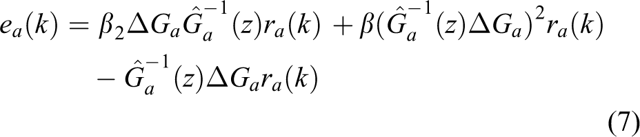
when the conventional off-line iterative control is augmented with a modified IMC and a real-time feedback controller Kb. In Figure 7(c), the improved IMC is introduced by tuning gain α(0 < α < 1) to minimize the effect of ΔGa. The acceleration output signal ya(k) of the EHST is disturbed by measurement noise n(k). In the combined control scheme, acceleration tracking errors in the jth iteration with different iterative controllers in Figure 6(a) to (d) are given by


Off-line iterative control scheme and its improved methods: (a) a conventional iterative controller, 41 (b) combined iterative controller using an off-line feed-forward inverse model controller and a real-time feedback controller, 41 and (c) combined the conventional iterative controller and an improved IMC. 36 IMC: internal model control.
Online adaptive controller
Off-line FIMCs and iterative controllers present the following specific disadvantages for the EHST system: In order to obtain a better acceleration waveform replication accuracy on the EHST, the transfer function model and its inverse model of the acceleration closed-loop system must be accurately estimated and designed, respectively, and the EHST needs repetitive excitations. However, repetitive excitations will break the specimen before it is subjected to the desired excitation level.
44
The estimated inverse model is usually considered as time invariant and linear, but dynamic characteristics of the EHST may be changed during real-time testing. However, OICs are strongly influenced by the specimen dynamics, which are nonlinear and of high order.
2
A real-time online iterative compensation method using inverse frequency response function may not be satisfied in the EHST system due to the computational burden of the fast Fourier transform and its inverse fast Fourier transform. The iterative rate of convergence and the acceleration waveform replication accuracy are closely related to the measurement and identification accuracy of the inverse model.
Hence, off-line compensation controllers, including OICs and FIMCs, and their improved methods cannot be applied in these nonlinear cases, and these shortcomings may be remedied by using an online adaptive controller in the EHST in which parameters of varying dynamics are simultaneously adapted. Some investigators turn to adaptive and intelligent control methods from off-line compensation controllers. These adaptive and intelligent control methods include AIC, 18,21,22,33,35,37,44 –48 MCS, 2,18,37,40,49 –53 ANFC, 27,28 APC, 20,32 AHC, 54 –56 and so on.
AIC based on the LMS algorithm was first proposed by Widrow and Walach,
95
and it has been successfully employed in the EHST.
18,21,22,33,35,37,44
–48
Some AIC approaches were employed for acceleration tracking control because payload dynamics are unknown and may change frequency characteristics of the EHST. Karshenas et al.
45
employed an AIC algorithm for shock testing on a shaking table. Vasilis et al.
47
presented a novel AIC framework with the LMS algorithm for accurate acceleration waveform replication in shaking tables, and the acceleration closed-loop transfer function was estimated by a discrete cosine transform LMS algorithm. Salehzadeh et al.
96
employed AIC for vibration test products, and they presented that the AIC approach was a suitable control technique in a nonlinear application such as vibration testing. An AIC scheme for the EHST system is shown in Figure 8(a), and other adaptive inverse controllers including filtered-X LMS, error-filtered, and inverse model LMS are shown in Figure 8(b) to (d), respectively, where the controller C(z) is online tuned by the LMS algorithm using the reference acceleration waveform input and its tracking error ea(k) defined by ea(k) = da(k) − ya(k) = ra(k)M(z) − ya(k), in which M(z) is a reference model of the adaptive controller. The LMS algorithm for updating weights in the negative instantaneous gradient is given by


Adaptive controllers for the EHST: (a) LMS, (b) filtered-X LMS, (c) error-filtered LMS, (d) inverse model LMS, and (e) MCS. EHST: electrohydraulic shaking table; LMS: least-mean-square; MCS: minimal control synthesis.
The MCS algorithm was originally developed by Stoten and Benchoubane 97 as an extension to the model reference adaptive control algorithm. The MCS is widely used in electrohydraulic servo systems including the EHST. 2,18,37,40,49 –53 A block diagram of the MCS structure is given in Figure 8(b). Control law of the MCS algorithm is chosen as the time-dependent state feedback strategy

where the feedback gain K ∈ R
n
and the feed-forward gain Kr are scalars, which are expressed as
Combined controller
It is well known that these adaptive control algorithms reviewed in “Online adaptive controller” section are popular approaches for the EHST system. However, these adaptive algorithms have their own advantages and disadvantages: High-quality waveform replication accuracy can be obtained after converging to their optimal solution. It is possible to exhibit poor transient response when it is initiated, especially, when the frequency bandwidth of the desired acceleration signal exceeds the frequency bandwidth of the acceleration closed-loop system of the EHST system.
Thus, there have been numerous attempts to improve the convergence rate of these adaptive control methods using some appropriate modification methods. Some combined control strategies were used to improve the tracking accuracy and the convergence rate in the EHST. Hessburg and Krantz 34 used an inverse model compensation combination with a TVC-FB to ensure stability of an EHST. August and Daniel 98 used a priori knowledge about the plant and split a controller into a long fixed part and a short adaptive part. The controller can be made more efficient by feeding back the error signal only in a desired frequency range, which is shown in Figure 9(a). Uchiyama et al. 44 developed a filtered-X LMS adaptive algorithm based on H∞ filter and a 2-DOF controller for an electrodynamic shaker, which is shown in Figure 9(b). Shen et al. 35 proposed a combined control strategy for the EHST, which combined merits of an off-line feed-forward inverse model and an online adaptive inverse controller based on RLS algorithm because the conventional LMS has slow convergence rate and poor regulation accuracy, and the combined controller is shown in Figure 9(c). Gizatullin and Edge 53 combined an inverse model with a velocity MCS (vMCS) for a multiaxis hydraulic test rig, which is shown in Figure 9(d). The vMCS controller cascaded the overall dynamic of the EHST, and an approximate inverse model of the controlled EHST as a feed-forward compensator was used further to enhance the performance of the multiaxis hydraulic test rig. Shen et al. 37 proposed a combined controller, which combined merits of the feed-forward inverse model and the MCS to improve the position tracking accuracy of the EHST, and its integrated controller framework is shown in Figure 9(e). Shen et al. 18 proposed a hybrid controller shown in Figure 9(f), which employed an online AIC based on LMS to obtain a high accuracy of the acceleration waveform after dynamic characteristics of the EHST have been improved using the TVC and the FIMC based on a modeling error compensator, which combines merits of the off-line FIMC and the online AIC.

Combined controller for the EHST: (a) adaptive inverse controller, 98 (b) 2-DOF controller based on AIC and a real-time feedback controller, 44 (c) combined feed-forward inverse model and AIC based on the RLS, 35 (d) feed-forward inverse model and a velocity MCS, 53 (e) combined MCS with a feed-forward inverse model, 37 and (f) hybrid controller combined the FIMC and the AIC based on LMS taken modeling error into consideration. 18 EHST: electrohydraulic shaking table; DOF: degree-of-freedom; AIC: adaptive inverse control; RLS: recursive-least-squares; MCS: minimal control synthesis; FIMC: feed-forward inverse model controller; LMS: least-mean-square.
However, the convergence performance of these combined controllers shown in Figure 9 will be directly related to the phase bandwidth of the acceleration closed-loop of the EHST. 18 If the frequency range of an acceleration command signal is larger than the phase bandwidth (−90° responding to frequency) of the controlled EHST, these reviewed adaptive controllers shown in Figures 9 and 8 will search in a wrong direction and finally diverge. 99 The convergence rate and divergence condition of the LMS algorithm were given in the literatures. 100,101 An unavoidable presence of a transfer delay during acceleration transmission in shaking tables 47 and the phase delay of the acceleration closed-loop system is one of the very important factors impacting the convergence rate of the LMS algorithm 18,47 because electrohydraulic actuators and servo-valves of the EHST have an inevitable delay in response to command signals due to inherent dynamics of electrohydraulic servo systems, which bring some bad effects on the convergence rate of adaptive controllers. 38 To solve the issue, various phase delay compensators have been presented. 102 –105 An adaptive controller based on a backstepping design method was proposed by Mahnaz 106 for a class of MIMO nonlinear systems with consideration of bounded time delays. An uncertain transport delay time in the transmission of an electrohydraulic servo-valve control system was presented, and a delay time variation can be effectively predicted and unconditionally removed. 107 Hence, a combined controller based on the LMS and an advanced delay compensation method 47 would produce very powerful techniques in the EHST.
Simulation evaluation analysis of main reviewed controllers
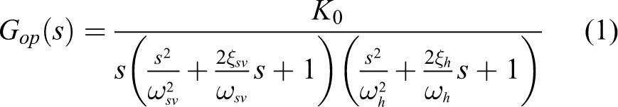
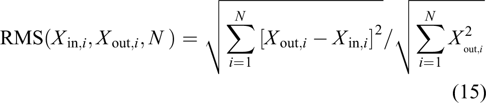
Simulation evaluation analysis for these reviewed controllers is performed in the section to verify whether these controllers can improve control performances and tracking accuracy of the acceleration waveform replication on the EHST system. Advantages, drawbacks, and their references of reviewed 12 controllers are listed in Table 1. In order to evaluate performances of 12 controllers, simulation is carried out using the EHST model presented in section “Dynamic model of the EHST.” A random acceleration reference signal with the frequency range of 0–20 Hz is employed to excite the nonlinear model shown in equation (1), and Figure 10(a) displays convergence results of an integral of square error (ISE, in dB). In order to quantitatively compare the acceleration tracking error of reviewed 12 controllers, a root mean square (RMS, in %) error is employed and is given by
The maximum ISE reduces from 5 dB with the conventional TVC controller to −55 dB with the combined OIC shown in Figure 7(c), and to −45 dB with the combined controller with the FIMC + LMS + modeling error compensator (MEC) shown in Figure 9(f). The maximum RMS error reduces from 9.26% with the conventional TVC controller to 2.45% with the combined OIC shown in Figure 7(c), and to 0.11% with the combined controller with the FIMC + LMS + MEC shown in Figure 9(f). The acceleration waveform error at t = 10 s reduces from 74.23% with the conventional TVC controller to 3.1% with the combined OIC shown in Figure 7(c), and to 4.5% with the combined controller with the FIMC + LMS + MEC shown in Figure 9(f). The acceleration time waveform error at t = 0.1 s reduces from 94%, 99.95%, 73.98%, 78.98%, and 84.56% to 10.08%, 29.43%, 40.38%, 18.16%, and 4.5% with different controllers, respectively.
Performances comparison of main reviewed controllers.

TVC: three-variable controller; FIMC: feed-forward inverse model controller; MCS: minimal control synthesis; MEC: modeling error compensator; OIC: off-line iterative controller; LMS: least mean square; A: high-fidelity replication accuracy; B: convergence rate; C: real-time compensation; D: cancel out modeling error.
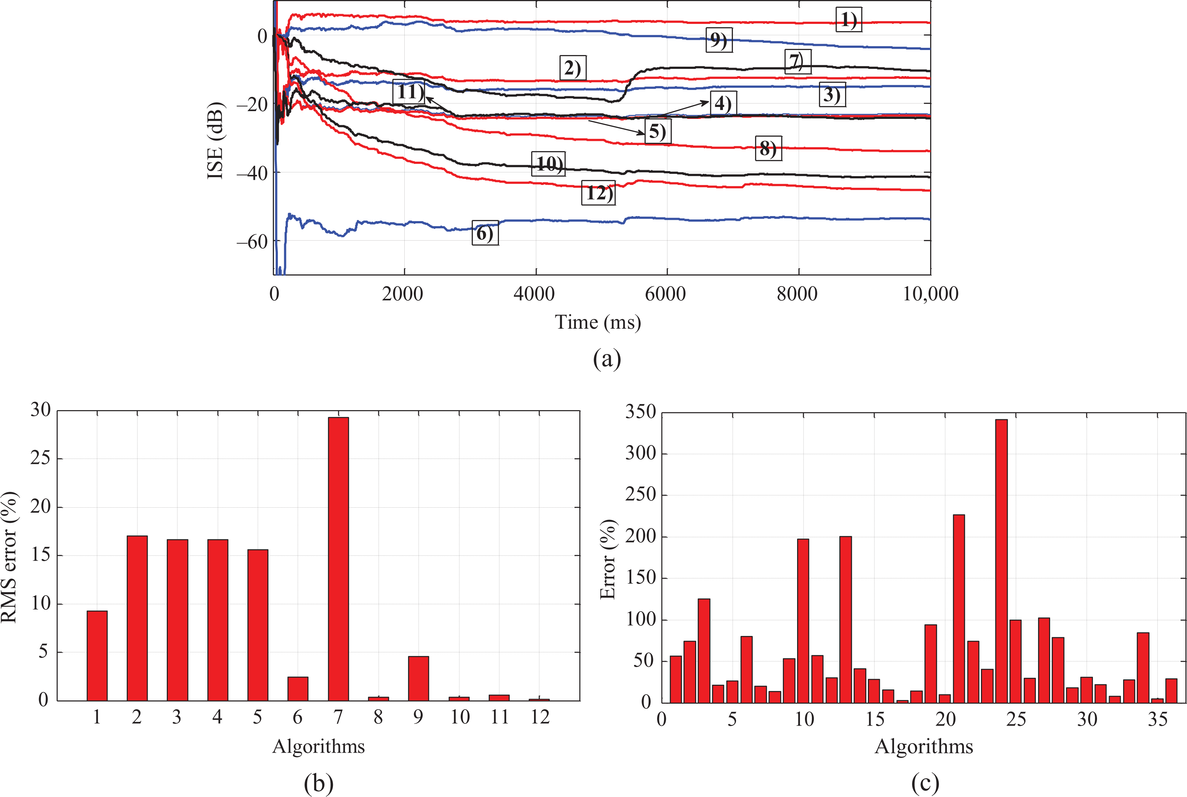
Comparison results of reviewed 12 controllers: (a) ISE (dB), (b) RMS (%), and (c) acceleration waveform tracking errors (%). ISE: integral of square error; RMS: root mean square.
Experimental setup of the EHST
An experimental EHST is shown in Figure 11. Specific parameters of the EHST are listed in Table 2. The EHST is controlled by six-DOF using eight servo-valves (G761-3004) manufactured by Moog Inc., Springfield, Pennsylvania, USA, with a 38 L/min flow capacity at 7 MPa supply pressure, and eight hydraulic actuators with 70 mm bore, 50 mm rod and their strokes ±0.1 m, maximum velocity of 0.5 m/s, maximum acceleration of 2 g without payload, platform size 2 × 2 m2, effective mass of 4 tons, and the acceleration frequency bandwidth of the EHST is in the range of 0–60 Hz with the TVC. Figure 12 is a schematic diagram of the EHST control system, in which eight LVDTs are attached to eight hydraulic actuators to measure their feedback displacements, and six-DOF acceleration output responses are measured by eight accelerometers mounted on the platform on the direction of each actuator. Reviewed controllers are performed in an xPC target system on the target computer. Drive signals are converted to analog signal by two D/A boards ACL-6126 and sent to eight servo-valves. Feedback signals including displacements, accelerations, and pressures are collected by two A/D boards PCI-1716.
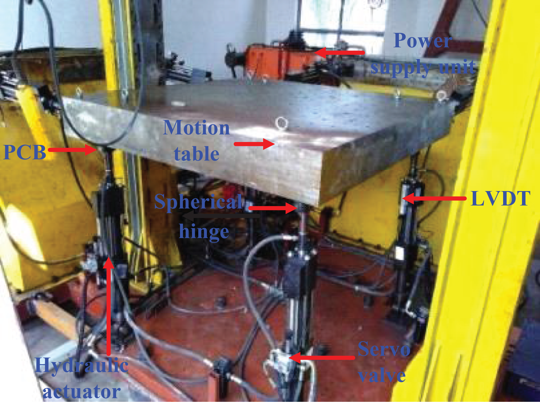
Experimental six-DOF EHST system. DOF: degree-of-freedom; EHST: electrohydraulic shaking table.
Main parameters of the EHST.
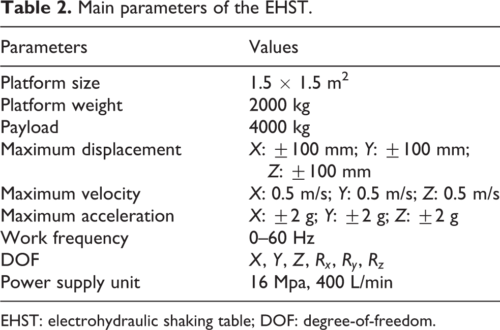
EHST: electrohydraulic shaking table; DOF: degree-of-freedom.

Schematic diagram of control system for the EHST. EHST: electrohydraulic shaking table.
Experimental evaluation analysis of main reviewed controllers
Dynamic model verification
The open-loop dynamic model of the EHST is shown in equation (1), and magnitude and phase frequency characteristics of model and experimental results are shown in Figure 13(a) and (b), whose simulation parameters are listed in Table 3. It can be noticed from Figure 13 that the hydraulic open-loop model is able to match the actual model satisfactorily. 19
Simulation parameters of the EHST.
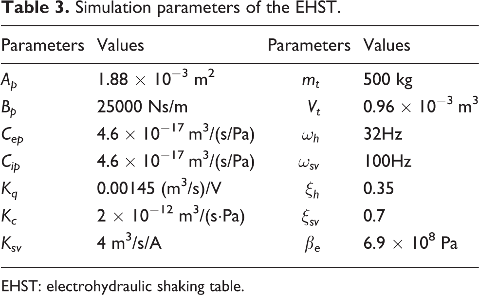
EHST: electrohydraulic shaking table.
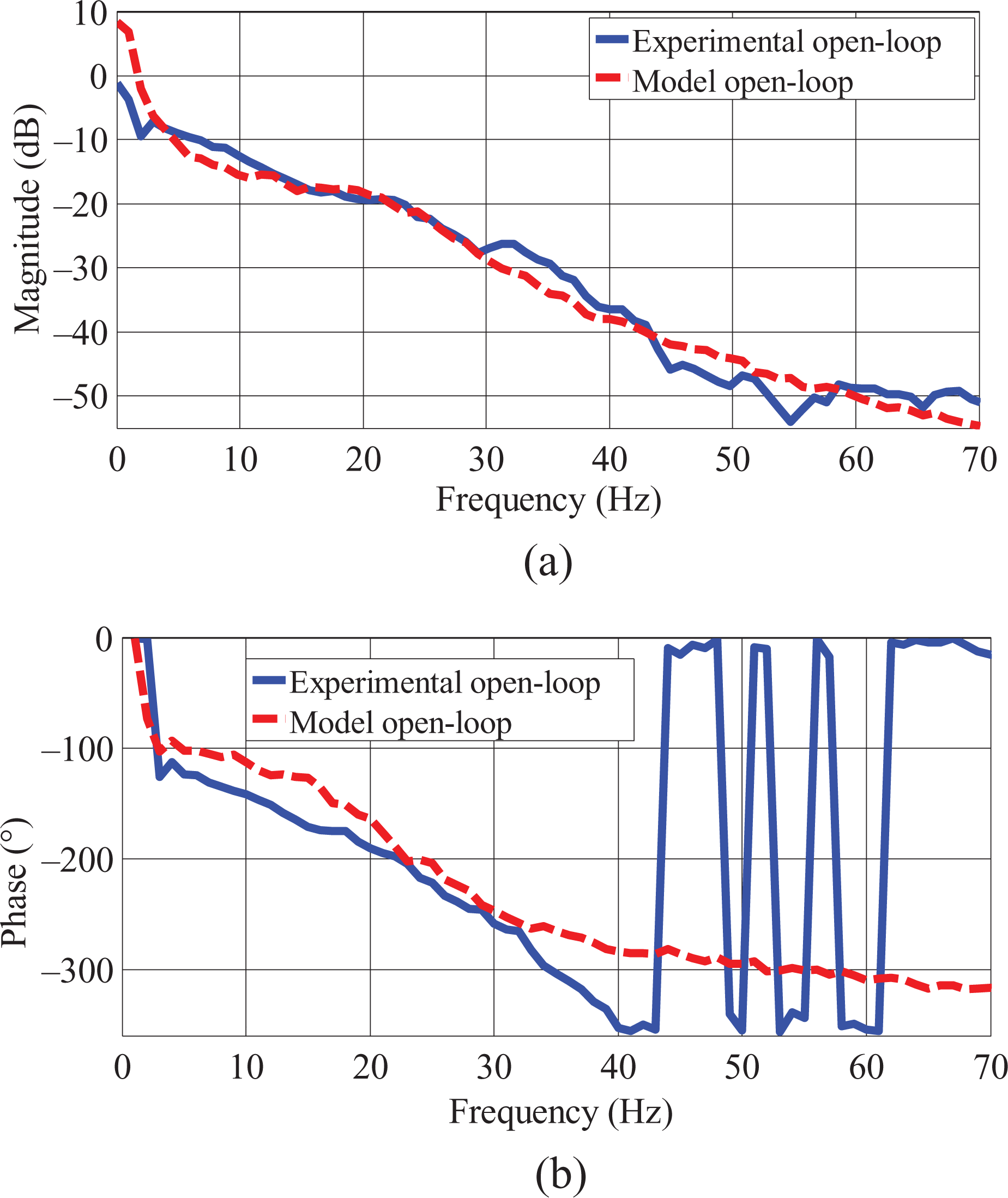
Comparison of open-loop model frequency characteristics between the hydraulic actuator and the actual EHST 19 : (a) magnitude and (b) phase. EHST: electrohydraulic shaking table.
Coordinate controller
Figure 14(a) and (b) show comparisons of differential pressure of eight hydraulic actuators with a condition of with and without the PSC, from which it can be observed that internal coupling forces of four actuators in the horizontal direction are decreased from 7MPa (supply oil pressure) to 0.3MPa and differential pressures of actuators in the vertical direction are relatively homogeneous. Experimental tuned parameters for the decoupling controller are listed in Table 4.

Coupling internal force of the redundant EHST: (a) without and (b) with the internal decoupling controller. EHST: electrohydraulic shaking table.
Tuned parameters for the internal force decoupling controller.

PSC: pressure stabilizing controller; LVDT: linear variable differential transformer.
Three-variable controller
To verify effectiveness of the TVC used in the EHST, a series of experimental tests on position and acceleration tracking control with the PID controller and the TVC have been carried out using 0.01 m position step signals, whose experimental results are shown in Figure 15. It can be seen from Figure 15 that the position tracking performance is significantly improved by using feedback gains Kvf, Kdf, and Kaf of the TVC-FB. Figure 16 presents acceleration frequency characteristics with the condition of with and without the TVC. 19 It can be seen from Figure 16 that the TVC-FF expands the frequency bandwidth of the acceleration closed loop from 25 Hz to 50 Hz in magnitude and from 12 Hz to 30 Hz in phase. Tuned main experimental parameters of the TVC are listed in Table 5.

Experimental results excited by position step signals (a) without and (b) with the TVC-FB controllers. TVC-FB: three-variable feedback controller.

Acceleration frequency characteristics with and without the TVC-FFs: (a) magnitude and (b) phase. TVC-FF: three-variable feed-forward controller.
Experimental parameters of the tuned TVC.
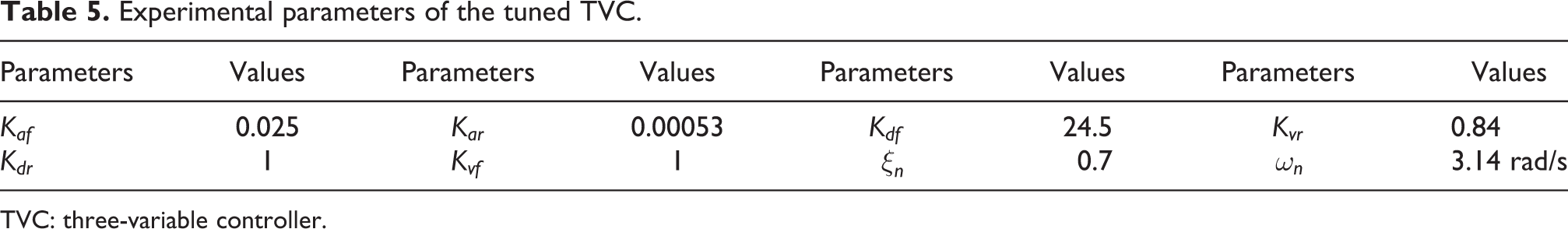
TVC: three-variable controller.
Model identification and its inversion design
Figure 17(a) shows the comparison of frequency characteristics of the acceleration closed-loop transfer function between the actual and the estimated models in time domain, from which it can be seen that the estimated acceleration signal can match the desired acceleration command signal satisfactorily. Figure 17(b) and (c) presents the comparison of frequency characteristics of acceleration closed-loop transfer function between the actual, estimated, and designed inverse models, and Figure 17(d) and (e) presents frequency characteristics of the measured and the identified modeling errors, which indicated that the designed inverse transfer function can effectively compensate the actual acceleration closed-loop system in the interesting frequency range, and the identified modeling error can match the measured modeling error satisfactorily. 19

Comparison of the measured, identified, and designed inverse models: (a) acceleration output of the actual and identified models; acceleration closed-loop system frequency characteristics of the measured and identified models: (b) magnitude and (c) phase; acceleration modeling error frequency characteristics of the measured and identified models: (d) magnitude and (e) phase.
Feed-forward inverse model controller
Experimental acceleration frequency characteristics using TVC, combination of TVC and FIMC, and combination of TVC, FIMC, and modeling error compensator are shown in Figure 18(a). As shown in the Figure 18(a), acceleration frequency characteristics with the TVC + FIMC perform better than that only with the TVC, and acceleration frequency characteristics can be further improved with the TVC + FIMC + MEC. 19

Experimental results of acceleration frequency characteristics with different compensators including the TVC, the TVC + FIMC, and the TVC + FIMC + MEC with β1 = 0.3 (a) magnitude and (b) phase. TVC: three-variable controller; FIMC: feed-forward inverse model controller.
Off-line iterative controller
In order to verify the effectiveness of the OIC, an acceleration random command signal with the frequency range of 0–12 Hz was used to excite the nonlinear dynamic model in equation (1) and its dynamic characteristics are shown in Figure 13. Figure 19 displays an ISE iterative results. It can be seen that system dynamic response has been improved a lot, especially, the mean square error reduces from −35dB with the conventional OIC to −65dB with the improved iterative controller, as shown in Figure 7(c). To demonstrate the performance of the acceleration waveform replication using Figure 7(c), the conventional OIC is conducted without the real-time feedback controller Kb and the improved IMC is carried out as a comparison. Figure 20(a) and (b) depict the acceleration tracking error of the conventional and the improved OICs shown in Figure 7(c) after each iteration with 30 Hz sine acceleration input, and the time domain response of two controllers after the third iteration is shown in Figure 20(c) and (d). As can be seen from Figure 7(c), the OIC exhibits a higher tracking accuracy than the conventional controller. Figure 20(e) presents the RMS error of Figure 7(a) and (c) after each iteration with sine input signal. As can be seen from Figure 20(e), the RMS error of Figure 7(a) after three iterations is 24.61%, 11.35%, and 11.05%, respectively, while that of Figure 7(c) is 15.56%, 5.32%, and 5.16%, respectively. It can be noticed that to reach the same tracking accuracy, the iterations needed are greatly reduced with Figure 7(c).

Simulation comparison of iteration results with different OICs: (a) the second iteration mean square error with the conventional iterative control shown in Figure 7(a) and its gain is 0.2, (b) the second iteration mean square error with the improved iterative control scheme shown in Figure 7(b) and its gain is 0.2, (c) the first iteration mean square error with the improved iterative scheme shown in Figure 7(c) and its gain is 0.3, (d) the second iteration mean square error with Figure 7(c) and its gain is 0.2, and (e) the third iteration mean square error with Figure 7(c) and its gain is 0.1. OIC: off-line iterative controller.

Experimental results of acceleration tracking error with sine input after each iteration: (a) conventional pure off-line iterative control shown in Figure 7(a) and (b) improved OIC shown in Figure 7(c); acceleration output responses with sine input after each iteration: (c) and (d) are conventional OIC shown in Figure 7(a) and improved OIC shown in Figure 7(c), and (e) acceleration RMS error after each iteration with sine input signal. OIC: off-line iterative controller; RMS: root mean square.
AIC and its combined controller with the FIMC
Experimental results of the acceleration waveform replication using five adaptive algorithms: (a) the LMS, (b) the filtered-X LMS, (c) the error-filtered LMS, (d) the combined controller based on the FIMC and the LMS, and (e) the hybrid controller shown in Figure 9(f) with β2 = 1 are compared. Figure 21(a) to (e) shows comparison of the experimental results of the acceleration command signals and the measured acceleration output signals using these five adaptive algorithms with different sine signals. Figure 21(g) to (k) shows the comparison of experimental results of acceleration command signals and measured acceleration output signals using these five adaptive algorithms with the frequency range of 2–40 Hz random signal. Figure 21(f) shows comparison results of integral time-weighted absolute error (ITAE) with these five adaptive algorithms shown in Figure 21(a) to (e). Figure 21(l) shows frequency characteristics of the acceleration closed-loop system using these five adaptive algorithms shown in Figure 21(g) to (k). Consequently, experiment results in Figure 21(a) to (l) show that the hybrid controller shown in Figure 9(f) yields a more remarkable improvement in the EHST system, compared to the other controller. So, it can be concluded that the hybrid controller shown in Figure 9(f) is effective in the acceleration waveform replication and meets the experimental requirement of the EHST.
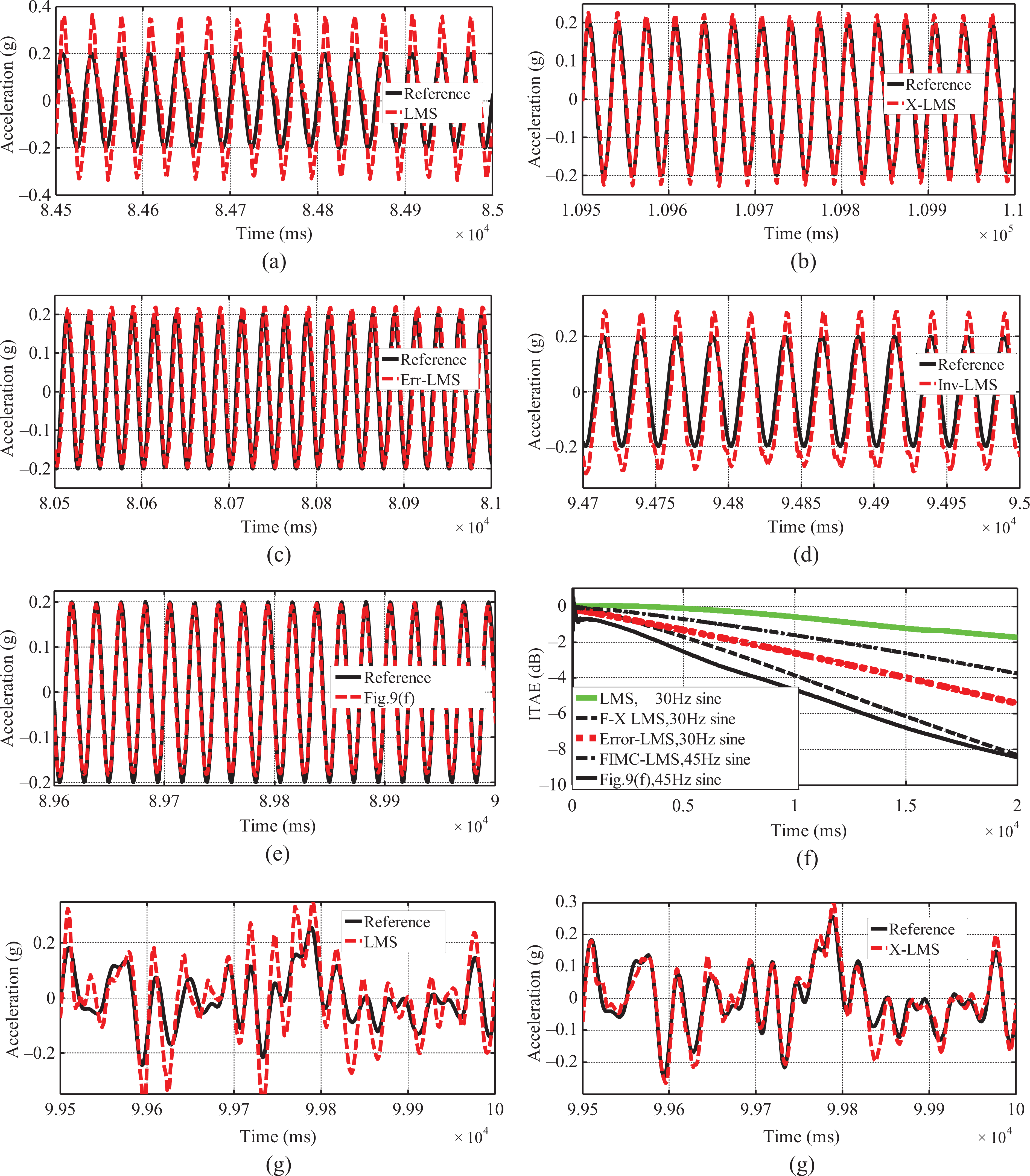
Experimental results of different adaptive controllers with different acceleration reference signals: (a) LMS with 30 Hz sine, (b) filtered-X LMS with 30 Hz sine, (c) error-filtered LMS with 30 Hz sine, (d) combined the FIMC and the LMS with 45 Hz sine, (e) the hybrid controller shown in Figure 9(f) with 45 Hz sine, (f) ITAE for different AICs with different reference signals, (g) LMS, (h) filtered-X LMS, (i) error-filtered LMS, (j) combined the FIMC and the LMS, (k) the hybrid controller shown in Figure 9(f) with the frequency range of 2–40 Hz random signal, and (l) frequency characteristics of Figure 21(g) to (k). LMS: least-mean-square; FIMC: feed-forward inverse model controller; AIC: adaptive inverse control; ITAE: integral time-weighted absolute error.
MCS and its combined controller with the FIMC
Comparisons of the position command and the measured displacement output with the traditional PID controller, the MCS, and the FIMC + MCS are shown in Figure 22(a)-(c), respectively, which are excited by the frequency range of 0-15Hz random signals. As can be seen from Figure 22, the acceleration tracking waveform performance with the FIMC + MCS can be greatly improved compared to the conditional PID controller and the MCS alone. Frequency response characteristics of the EHST position closed-loop system with the FIMC + MCS and the PID controller are compared in Figure 22(e). Comparison of experimental results show that the frequency bandwidth of the position closed-loop system in the EHST already increased up to 40 Hz according to the −100° phase condition.

Experimental results of the position tracking control: (a) the PID, (b) the MCS, (c) combined controller based on the FIMC + MCS with the range of 0–15 Hz position random signal, and (d) comparison of frequency characteristics using the PID and the FIMC + MCS with the range of 0–40 Hz position random signal. PID: proportional-integral-derivative; MCS: minimal control synthesis; FIMC: feed-forward inverse model controller.
Combined controller with the FIMC and the adaptive RELS
Comparison of the position command and the measured position output in time domain excited by a random signal with the frequency range of 0–20 Hz using the traditional PID controller, PID with feedback compensation, the FIMC, and the FIMC + RLS shown in Figure 9(c) is shown in Figure 23(a), and comparison of acceleration output responses using the FIMC + RLS is shown in Figure 23(b). It can be seen from Figure 23 that the position and the acceleration tracking performances with the FIMC + RLS are more satisfactory than those with the PID controller, the PID with feedback compensation, and the FIMC.

Experimental results of the position and the acceleration tracking control with different controllers: (a) the position tracking with the PID controller, the PID with the acceleration and the velocity feedback compensation, the FIMC, and the FIMC + RLS and (b) acceleration output responses with the FIMC + RLS. PID: proportional-integral-derivative; FIMC: feed-forward inverse model controller; RLS: recursive-least-squares.
Concluding remarks
A number of control techniques have been investigated extensively in recent years to improve the acceleration waveform replication accuracy on EHSTs. In the article, an experimental EHST and its nonlinear model are established to verify acceleration tracking control performances of these reviewed controllers. Different controllers have been addressed including the PID controller, the TVC controller and its improved controllers, the FIMC and its improved controller combined with modeling error, and adaptive controllers and their combined controllers. To compare control performances of these controllers, a number of experiments are carried out on an actual EHST system. From these simulation and experimental results of the acceleration waveform replication, the following conclusions can be made: A coordinate controller is the most important controller to decouple the internal coupling force in the redundant EHST because geometric effects, different parameters, and installation error of the eight actuators can cause the EHST cannot work normally. Hence, the coordinate controller, including the transform matrix, the PSC, and the PID controller, of the redundant EHST must be designed and tuned first. The most popular controller applied in the EHST is a PID controller, but it can only improve the acceleration waveform replication accuracy in a very limited range because hydraulic position servo systems regularly exhibit a poor damping ratio and a lower frequency bandwidth. A compensated PID controller using the velocity and the acceleration feedback compensation can improve the natural frequency and the damping ratio of the EHST. The TVC is a commonly used controller employed in the EHST because it can expand the frequency bandwidth of the acceleration closed-loop system by tuning TVC-FF and increase the damping ratio and stability of the EHST by tuning TVC-FB. The TVC is employed in engineering applications including the largest E-Defense shaking table in Japan. Feed-forward inverse model compensation methods improve the acceleration waveform replication accuracy significantly, but a modeling error occurs between the estimated model and the designed inverse model with the actual model of the EHST and system uncertainties; so, some combined controllers, including a modeling error compensator and an internal model controller, are designed to solve the problem. Some compensation methods of the stable inverse model must be studied because the identified model of the acceleration closed-loop system is a nonminimum phase system and its inverse model is unstable. Off-line compensation controllers, including the TVC controller, the FIMC, and the OIC, can yield a better frequency bandwidth of the EHST using feed-forward and feedback compensation, but they cannot adaptively tune parameters to suppress variable dynamic characteristics of the EHST during real-time testing. Hence, a high-fidelity acceleration waveform cannot replicate on the EHST. Some adaptive controllers can obtain a high-quality acceleration waveform replication after convergence to their optimal solution, but they are possible to exhibit poor transient response when the frequency bandwidth of the desired acceleration signal exceeds the frequency bandwidth of the acceleration closed-loop system. Some combined controllers including FIMC + AIC/MCS/RLS can accelerate the convergence rate of these adaptive controllers and improve the acceleration tracking accuracy. These combined controllers combined the advantages of online adaptive controllers, off-line FIMCs, modeling error compensators, the IMC, time delay compensators, and so on. Combination of these several research areas has given promising results in a few studies. These combined controllers can extend to other control systems. The coordinate controller and the PID controller are tuned first, the TVC-FB is then employed to improve the stability of the EHST, and the TVC-FF is then employed to expand the frequency bandwidth of the acceleration closed-loop system. A complete servo controller for the EHST is implemented. The FIMC, the OIC, and their combined methods can be used to further improve acceleration frequency characteristics and expand the frequency bandwidth of the acceleration closed-loop system. Online adaptive controllers and their combined methods can be employed finally to obtain a high-fidelity acceleration waveform accuracy if fixed dynamic characteristics of the EHST are changed during real-time testing subjected to disturbances.
Consequently, these reviewed control techniques not only be utilized for the six-DOF redundant EHST but also are effective methods for the other closed-loop control systems.
Footnotes
Acknowledgment
The authors would like to thank the editor, associate editors and anonymous reviewers for their constructive comments.
Declaration of conflicting interests
The author(s) declared no potential conflicts of interest with respect to the research, authorship, and/or publication of this article.
Funding
The author(s) disclosed receipt of the following financial support for the research, authorship, and/or publication of this article: This research was supported by the National Natural Science Foundation of China (no. 51575511), the Fundamental Research Funds for the Central Universities in China (no. 2015XKMS025), the Priority Academic Program Development of Jiangsu Higher Education Institutions (PAPD), and the Qing Lan Project in Jiangsu province.