
Abstract
Enhancement of human performance using an intelligent assist device is becoming more common. In order to achieve effective augmentation of human capacity, cooperation between human and robot must be safe and very intuitive. Ensuring such collaboration remains a challenge, especially when admittance control is used. This paper addresses the issues of transparency and human perception coming from vibration in admittance control schemes. Simulation results obtained with our suggested improved model using an admittance controller are presented, then four models using transfer functions are discussed in detail and evaluated as a means of simulating physical human–robot interaction using admittance control. The simulation and experimental results are then compared in order to assess the validity and limitations of the proposed models in the case of a four-degree-of-freedom intelligent assist device designed for large payload.
Keywords
Introduction
Human augmentation is an application of robotics in which the force capability of a machine is combined directly with the skill of a human user. The main challenge for human augmentation systems is to perceive the environment and the human intention and then to respond to both adequately and intuitively. Applications involving moderately large payloads often make use of admittance control, in which a handle or a force/torque sensor is used to detect human intention. 1,2
Although stability issues associated with impedance control have been studied in depth, 3 –6 fewer studies have been devoted to admittance control, 7 –9,44 or to its modeling. 10 Furthermore, the results presented in these studies are not consistent with observations reported elsewhere 11,12 or with the experimental results obtained in our research. Moreover, in our previous research work, 13 an intelligent assist device (IAD) prototype was characterized and an admittance controller was designed according to the IAD specific characteristics. However, a general physical interactive theoretical model allowing to mathematically demonstrate the stability margin for a general IAD was not developed.
Therefore, this paper presents a new physical interactive model enabling simulations of general IADs. In addition, the proposed model is compared with experimental results on the stability of IADs that use an admittance control scheme. The goal of this work is to evaluate the adequacy of simulations of physical human–robot interaction (pHRI) obtained using the proposed improved models. Such models could also be used for force rendering in haptics, as presented elsewhere, 14,15 or in teleoperation. 16 The underlying challenge in the development of admittance controllers is to increase transparency and thereby improve interaction and reduce mechanical vibrations to below the threshold of human perception. 17
The following definitions will help the reader to understand the concepts described in this paper. Vibration is defined as a transient underdamped response obtained at a constant setpoint and generating exponential decay (real part of the dominant complex pole) of a sinusoidal oscillation (imaginary part of the dominant complex pole pair). When changes in the setpoint are continuous and highly dynamic, a sinusoidal oscillation is observed, usually called a vibration or sometimes “unstable behavior” in the literature. Transparency refers to the capability of the controller to compensate (feedforward controller) for hardware imperfections such as inertia, friction, backlash and vibration such that the payload and mechanism are hidden while a model (impedance or admittance) is rendered to the user.
18
Two frequency bandwidths are considered here, in accordance with human perception of vibration (properties of skin mechanoreceptors) 19,17,20 and with human musculoskeletal response (properties of the human body model). 21 It has been found previously that a typical operator is able to control a frequency lower than 10 Hz (i.e. reduce the vibrational amplitude) while higher frequencies are associated with vibrotactile stimulation and can be perceived as a disturbance for a collaborative task. 20,21
With respect to the state of the art in admittance controller design and technology, the main contribution of this paper is to propose a new model representing physical interaction that can match observations presented in our previous research work 42,13,46 and in others, 11,12 thus allowing humans to operate an IAD more efficiently. The long-term objective is to develop a model of the interaction with industrial IADs in order to understand the effects of each parameter (such as belt stiffness, friction, delay) on the interaction in order to help in designing better cooperative systems. We describe the method used to identify the mechanism physical properties in order to improve the motion controller response and ultimately transparency. The third section presents analysis based on transfer functions and simulations. The simulation results are then compared with the experimental results. Finally, a discussion of the comparison is presented and conclusions are drawn.
Admittance model
Two main types of control are used in haptic applications and pHRI, namely impedance with force feedback and admittance with positional feedback. 22 This article refers to impedance and admittance controllers without reference to the feedback type. Both types of controller may be called “impedance” in the literature. Impedance controllers accept a measurement of displacement as input and respond with an adjustment of force. Devices controlled using this method should ideally have low inertia and friction (no hardware imperfections, if possible) since the user will inevitably feel these superfluous forces if compensation for them is inadequate. In contrast, admittance controllers accept a measurement of force as input and respond with a displacement. 12,11,23,24,45 Impedance controllers represent the vast majority of the controllers proposed in the literature and deployed in applications, while admittance controllers are less common since the hardware cost is higher. 25 Their use in pHRI applications has been suggested previously. 26
Because of the high inertia and friction, it would be too difficult for a human operator to impart movement to the IAD used in this work (shown in Figure 18 and presented in Appendix I), making impedance controllers ill-adapted to the situation, even when a force sensor is used. Prior experience teaches us that the minimal achievable virtual inertia would be about half the real inertia 27 instead of a tenth with admittance control as suggested previously. 11,12 An admittance controller with positional feedback is therefore preferred for both free movement and the constrained motion characterizing our application.
Therefore, we have recently designed a torque-controlled IAD using a feed-forward torque compensation for controlling the actuators aiming at reducing both inertia and friction. 13,42,46 However, those equations did not take into account the dynamic of the physical interaction with the human operator. An initial system model is presented below in order to explain certain aspects to consider when using an admittance controller.
Modeling physical interaction
The one-dimensional admittance equation is written as follows

where fH
(t) is the interaction force (i.e. the force applied by the human operator), m is the virtual mass, c is the virtual damping, k is the virtual stiffness, x
0(t) is the equilibrium point, and x(t), ẋ(t), and
Since simulation of free motion is desired, k,

The set-point trajectory followed by the end-effector can be described a priori as a position xd(t) or as a desired velocity ẋd(t). For velocity control, the desired velocity can be written in the Laplace domain as follows

The desired reference in position control then becomes

where X(s) refers to the Laplace transform of
Figure 1 presents the control scheme, in which the velocity controller used in the experiments is of the proportional type. Previous experiments showed the effectiveness of proportional gain, 31 thus allowing us to avoid the drawbacks of increased acceleration noise due to the derivative gain and possible decreases in bandwidth due to the integral term (by accumulating error history from human input).

Control scheme used in this work.
Experimental results
The main contribution of this paper is an improved model of interaction in a closed loop. Results found in the literature are not consistent and suggested where controller design could be improved. A device described previously in Appendix I was used with an admittance controller. This set-up provided clear experimental proof that there is a lower boundary on the virtual mass that the system can stably render, which is consistent with results presented previously. 11,12 Below this mass, vibrations or instability may occur when the operator is stiff (a stiff environment is known to favor system vibrations or instability 27 ). We also obtained experimental proof that a high virtual mass can be rendered even when the operator is stiff.
The minimal virtual mass that can be rendered for different values of virtual damping was determined experimentally for the X and Y axes of the IAD. These masses are shown in Figure 2. In the vibration-free zone, human perception of vibration is negligible for any operator motion, even under conditions of stiffness. 17 The line separating the zones was obtained by lowering the virtual mass until the operator sensed a vibration that made the interaction uncomfortable. This test involved quickly varying interaction forces and/or stiff operator movements. When determining the minimal mass, one should ensure that the velocity controller is not the cause of device vibrations. It is apparent on the graphs that a critical damping exists (60 Ns/m for the IAD used here) below which it becomes difficult to render fast dynamics. Moreover, the ratio of minimal virtual mass to virtual damping seems to converge to a limit value as damping increases. Stability constraints are more stringent for motion along the X axis than along the Y axis, due to greater inertia and compliance along the X axis in the device used here.

Stability limits for motion along the X and Y axes: ratio of minimal virtual mass to virtual damping versus virtual damping. The area below the plotted line corresponds to vibrations that can be felt by the operator, while the area above is the vibration-free zone.
The experimental results show that in a stiff environment with a given damping, a minimal virtual mass exists for which the IAD is vibration-free (sometimes termed stable in the literature). Our experiment led to the observations summarized below. There is no evidence for a maximal mass leading to vibration and then instability. This result is in accordance with statements made in previous reports without experimental validation or detailed explanation using a physical model,
11,12
and in contrast with conclusions reached elsewhere that there is no evidence for the existence of a minimal virtual mass while a maximal authorized mass might exist.
7
–9
All authors agree that increasing virtual damping decreases system transparency but improves the perception of vibration or reduces distraction due to mechanical vibration. Experimental results show that it is counterintuitive to cooperate under conditions of high virtual-mass-to-damping ratio, since movement of the payload is difficult to stop or decelerate once started.
These observations are sufficient to justify the study of an improved physical model. The development of this model from open to closed-loop feedback is presented below.
Towards the development of an effective model
The mathematical models used to analyze the regions of cooperation, vibration and instability as identified experimentally and described in the preceding section are presented below. The proposed analysis is based on the Laplace plane, the Routh–Hurwitz stability criterion and simulations suggested previously. 32
The first model considers an ideal case: both the controller and the mechanism are transparent. In other words, the admittance causality is able to hide the mechanism suitably from human perception. A transfer function called imperfections 33 is also added to represent different issues such as signal filtering (reducing the bandwidth), imperfect control (controller gains are not accurate) and small delays. Using these assumptions, models with the human operator in open-loop and closed-loop feedback are analyzed.
The open-loop model
In this model, it is assumed that the operator simply applies interaction forces as represented in Figure 3 where s is the Laplace variable, m is the virtual mass, c is the virtual damping, fH(t) is the interaction force (i.e. the force applied by the operator), x(t) is the position, x′(t) is an intermediate result, and T is a time constant related to parameters modeling bias and imperfection.

Simple open-loop model.
The transfer function can be written as follows:

where V(s) is the Laplace transform of the velocity v(t) (time derivative of x(t)) and FH(s) is the Laplace transform of fH(t).
For a given input, the steady-state velocity is lower for a higher virtual damping. The virtual mass has a low-pass effect, thereby filtering force sensor noise and high variation of the interaction force (when the operator applies physical effort to the end-effector). However, if the virtual mass is too high, cooperation becomes counterintuitive since acceleration takes time and once in progress, is difficult to oppose.
The simplified closed-loop model
The second model assumes that the operator acts as a spring system that tends to remain at a given position, thus simulating stiffness, as represented in Figure 4 where KH is the human operator stiffness and xhd(t) is the desired operator position (set at zero in the simulations). The human arm model is based on a previous study where an estimation of human arm stiffness was performed in a human–robot cooperative calligraphy task. 28
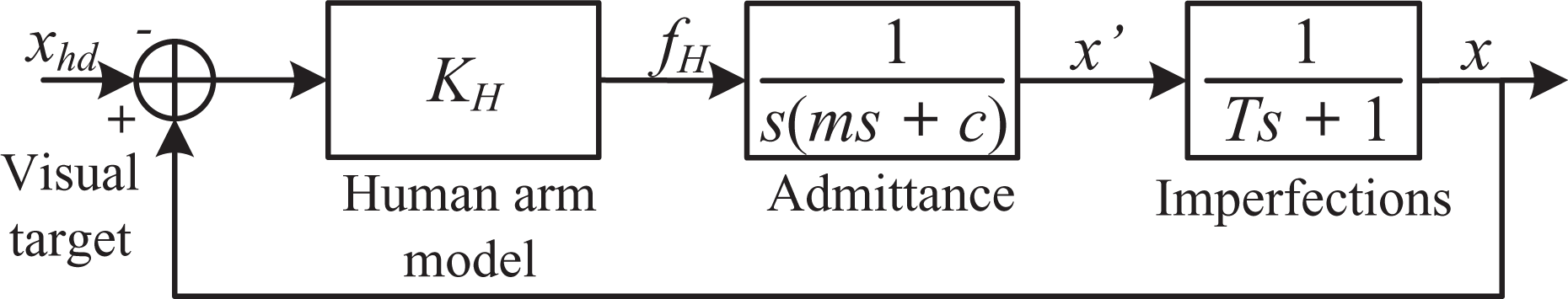
Simple closed-loop model.
The transfer function can be written as follows:

We shall now analyze the stability of the closed-loop transfer function using the position of its pole in the s-plane (complex plane on which Laplace transforms are graphed) along with the Routh–Hurwitz stability criterion. Applying the Routh–Hurwitz criterion to equation (6), the condition under which the system is stable is defined as follows:

For a given damping, imperfection and stiffness, equation (7) yields three cases, namely: (a)

For example, for the realistic values c = 20 Ns/m, T = 0.1 s, KH = 550 N/m, m < 1.14 kg is obtained.
For case (b), obtained from a well-designed virtual damping, we learn that a greater mass leads to a more underdamped system, without crossing to the right-hand side of the Laplace plane, as shown in Figure 5. The pole starting points are each represented by a dot and the parameter variation is directed toward a square. It should be pointed out that these graphs show the evolution of the poles with regard to a varying parameter and therefore do not represent a classical root locus. The evolution of the poles is very similar to what would be obtained with a simple mass–damper–spring system. This analysis gives a maximal mass with which it is intuitive to collaborate for a given damping, since once the mass is in motion it is difficult to stop. In practice, the oscillations so induced are of very low frequency and the operator would be able to control the system.
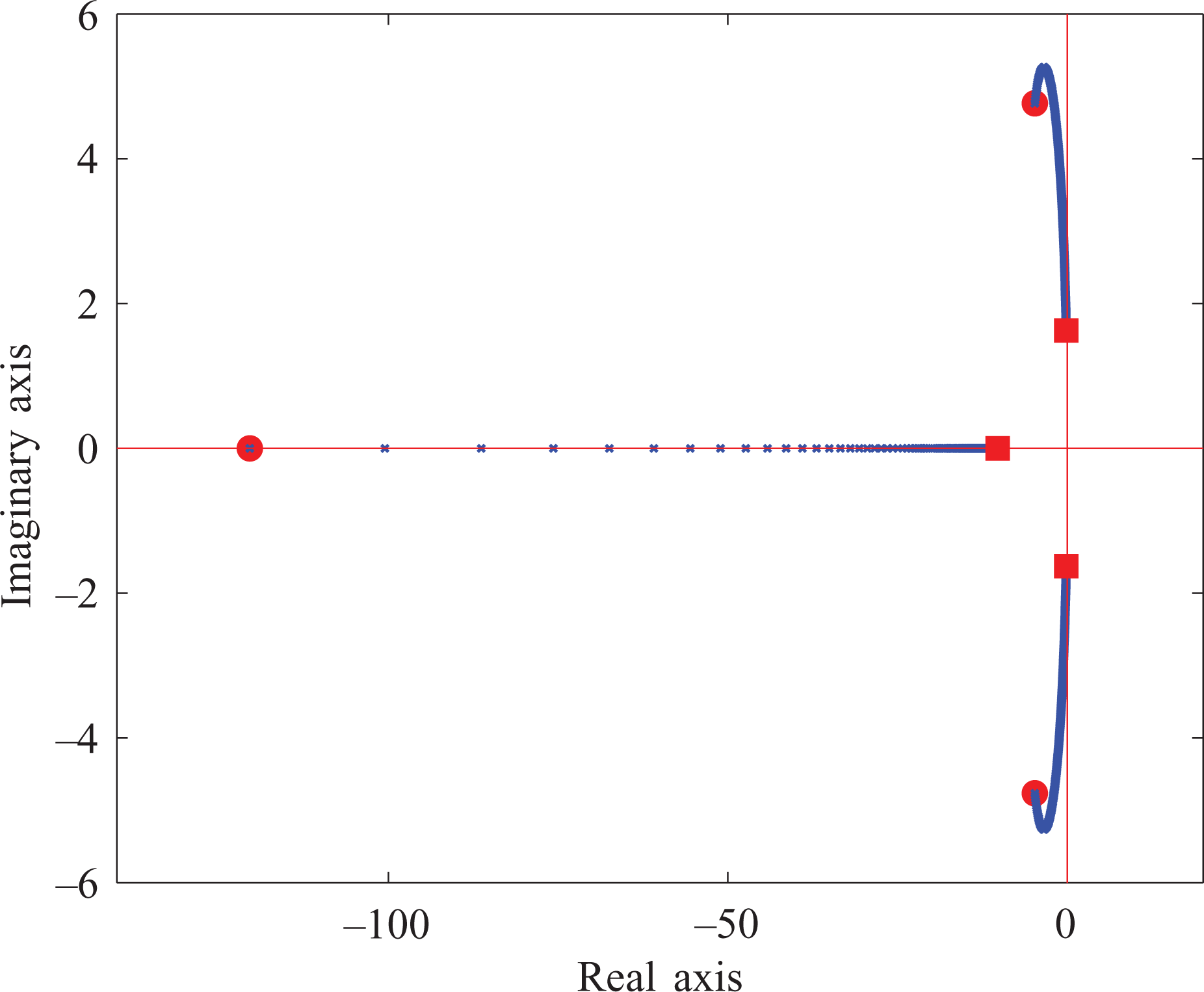
Poles of the simple closed-loop model for case (2) (
Based on this model, the following observations can be made: if the virtual mass increases, the natural frequency and damping ratio decrease and stabilize asymptotically as shown in Figure 6; for a low virtual mass, the system is more damped but the frequencies are higher; even if the system is more damped for low virtual masses, the result is worse since the vibrations occur at higher frequencies; these oscillations make control of the device more difficult and uncomfortable since they are in the skin mechanoreceptor sensitivity range;
34
with higher virtual mass, the damping ratio is lower but the low frequency of the vibration makes it manageable for the human operator; higher virtual mass reduces the impact of the force sensor noise.

Natural frequency and damping ratio for underdamped poles as a function of virtual mass varying from 1 to 200 kg, c = 120 Ns/m, T = 0.1 s and KH = 550 N/m.
For case (c) where

Poles for a simple closed-loop model for case (2) for a virtual mass varying from 1 kg (circle) to 200 kg (square), c = 20 Ns/m, T = 0.1 s and KH = 550 N/m.
Based on this analysis, we can conclude the following: although a theoretical stable zone exists for case (c), it is not practical since it may not be reachable and if it were, it would lead to a very underdamped response; it is therefore preferable to modify the virtual damping and mass in order to satisfy case (b) with a damped response perception, since the cooperation must not only be stable but also intuitive and free of vibration; the model presented in this section indicates that there is a minimal virtual damping below which the system is unstable; the model cannot predict the existence of a minimal mass, as obtained in the experiments and reported in the literature.
11,12
Although this simple model may be used as a guideline, it does not suitably represent reality. An improved model was therefore developed, as described below.
Proposed improved closed-loop model
A more elaborate model of the IAD developed in order to alleviate the drawbacks of the simple model presented above is illustrated schematically in Figure 8, where mR represents the motor inertia, CB represents the mechanical transmission damping, KB represents stiffness, CR is the viscous friction acting on moving mass MR, and F is the actuation force. In the IAD used in this work, circular toothed belts transmit the power from the actuators to the end-effector. Therefore, CB and KB represent belt damping and stiffness.

Improved IAD model.
Open-loop version
The open-loop model is represented in Figure 9, where KP is the control gain.
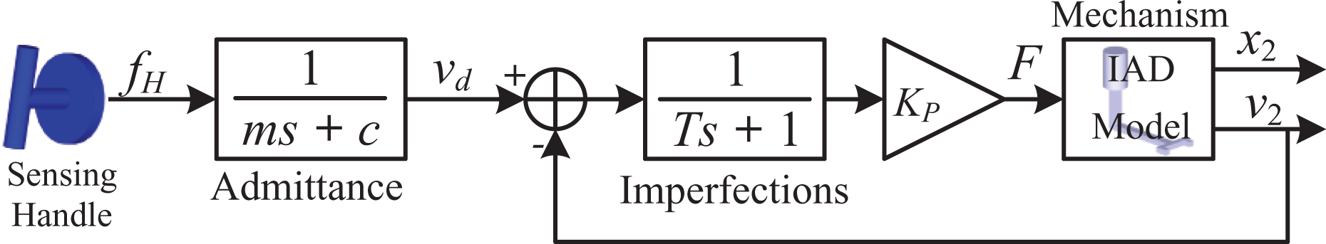
Improved open-loop model.
The human force input is transformed into a velocity through the admittance law stated previously in (3). The velocity error is then filtered, sent to a controller (proportional gain acting as a follower) and the resulting command F(s) is sent to the IAD actuators. This model allows the inclusion of compliance, control imperfection and delay. The corresponding transfer function is given in equation (9) developed in Appendix II. The location of the poles, as a function of the virtual mass, is shown in Figure 10. It should be noted that the ratio of virtual mass to damping corresponds to the real pole (which varies with the virtual mass) while the others remain constant.

Poles of the improved open-loop model for a virtual mass varying from 10 kg (circle) to 200 kg (square), c = 20 Ns/m, T = 0.1 s, Kp = 10,000,
In this case, the effect of the virtual mass is quite simple: as it increases, so does its filtering effect, and the desired velocity is accordingly smoother. Figure 11 shows the time response to an operator step force input for low and high virtual mass. A high virtual mass helps to decrease the amplitude of the vibrational envelope. If the virtual mass is low, the response may be underdamped when the interaction force varies abruptly. This is in accordance with the experiments, in which a low virtual mass led to vibration.

Human force step response:
Figure 14 compares the simulations and experimental results. The open-loop curve was obtained by simulating different virtual masses for a given virtual damping. The minimal mass was selected when the velocity difference between a maximum and minimum was equal to 0.15 m/s for a force of 100 N applied for 3 seconds. These values were selected heuristically and from experimental results.
The open-loop model provides partial explanation of the vibration problem (human perception of an underdamped response) including transmission compliance, time delay and control imperfection in the case of low virtual mass.
Improved closed-loop version
The open-loop model presented in the preceding subsection leads to results that are consistent with experiments in the sense that it predicts the existence of a minimal mass. However, it does not explain the minimal mass effect for low damping. A detailed model with the human operator in a closed loop was therefore studied.
The improved model requires a human arm dynamic model in the closed-loop control system. A detailed model including the vestibular system, reflex mechanisms and other motor functions has been presented previously. 35,36 Three-dimensional arm modeling in space could also be used. 37 However, we need an end-point impedance model applied in collaborative work with a robot. 38 Also, since another study suggests that visual perturbation does not influence stiffness control, 39 the visual delay was removed. Finally, since the dynamic model is represented in one degree-of-freedom (1 DOF), a damping parameter CH was added over the previous simple model presented in Figure 4 as other works suggest. 28 Our human arm model is then represented schematically in Figure 12. The corresponding transfer function is given in equation (11) in Appendix I. Pole location is shown in Figure 13 for a varying virtual mass.

Improved closed-loop model.

Location of the poles of the improved closed-loop model for a virtual mass varying from 0.1 kg (circle) to 200 kg (square),
An underdamped response and an unstable zone occur below a given virtual mass, as observed in the experiments. Figure 14 compares the stability or vibrational limits obtained in simulations and experiments. For a perturbation of the force of 1 N for 0.05 s, the minimal mass was obtained when the oscillations reached an amplitude of 0.013 m/s. These values were selected heuristically and from experimental results. The minimal stable mass was obtained by lowering the virtual mass in the simulation until the system became unstable.

Comparison of the ratio of minimal stable/acceptable virtual mass to virtual damping obtained using simulation models and experimental data.
The results are very similar to experimental observations: the model satisfactorily predicts the existence of a minimal virtual mass and characterizes the variation thereof with respect to virtual damping; no maximal virtual mass leading to instability was found, which is consistent with the experimental results obtained here and previously
11,12
(however opposite conclusions have been reached elsewhere,
7
–9
as explained above); for very high virtual masses, interaction is not intuitive since the motion is very underdamped and difficult to stop once started.
It would be possible (though more difficult and not intuitive) for the operator to compensate for such motion, since these phenomena occur at very low frequency. It has been found experimentally 11,12 and confirmed with the present model that the minimal virtual mass has a much greater impact than does the maximal intuitive virtual mass. The main reason for this is that the virtual mass must be minimized in order to reduce the required force input from the operator. The minimal mass is therefore obviously the primary concern.
Transmission stiffness
Figure 15 shows the poles of the improved open-loop model for varying transmission stiffness. It is apparent that stiffer transmission leads to better results while compliant transmission may lead to vibration as shown in Figure 16. However, a somewhat compliant end-effector may be beneficial since it does not affect transmission stiffness but limits the “stiffness” of the environment.

Location of the poles of the improved open-loop model for transmission stiffness varying from 10,000 N/m (circle) to 500,000 N/m (square), c = 20 Ns/m,

Human force step response for the improved open-loop model for low and high transmission stiffness (
Discussion
The existence of a minimal virtual mass that eliminates perceptible vibration was observed experimentally and was explained using the improved model. It was found that the system may vibrate even in an open-loop configuration if the virtual mass is low and the force profile is highly dynamic. This result is related to the velocity controller and to the mechanism bandwidth. The virtual mass should be high enough so that the system does not oscillate with an open-loop controller, since otherwise the admittance equation will not be well rendered, thus reducing transparency.
It was also found that in a stiff environment (i.e. in a closed loop), the system may oscillate and even become unstable if the virtual mass is too low. It is clear that if the mass is low enough for the system to oscillate when the controller is in an open-loop configuration, it is very likely to oscillate with a closed-loop controller. The virtual mass must be high enough so that the operator will be comfortable in both control modes. The notion of comfort is associated with the perception of vibrations, which are related to the oscillation frequency and amplitude. High-frequency vibrations are less comfortable since they are impossible for the operator to manage, due to physical 21 or cognitive limitations. The control system, virtual damping and mechanism must be well designed in order to allow ergonomic and vibration-free interaction. It should also be noted that the human perception bandwidth varies significantly between the fingertips and the larger muscle groups. 21,40,41 The required operator forces should therefore remain low. Although it is possible to manage low-frequency oscillations that occur when the virtual mass is large, interaction may be less intuitive in such cases, as explained previously.
Figure 17 presents the Bode plot of the open-loop models (simple and improved) for two virtual masses. For the improved model, the cut-off frequency is 0.16 Hz at m = 120 kg and 1.3 Hz at m = 10. In addition, the 6.4 dB peak observed at m = 10 can lead to overshooting and vibration. As shown on Figure 17, the simple model is never unstable as we never reach a phase passing through −π/2 rad and 0 dB gain. However, this does not have any consequence on perceptible vibrations as in higher frequency on the Bode plot, the system can oscillate in transient response. Then, an operator can stimulate this response by applying an opposite force on the handle which generates continuous oscillation until the arm stiffness is reduced. When using the improved model, the system could be unstable with a 42 dB (
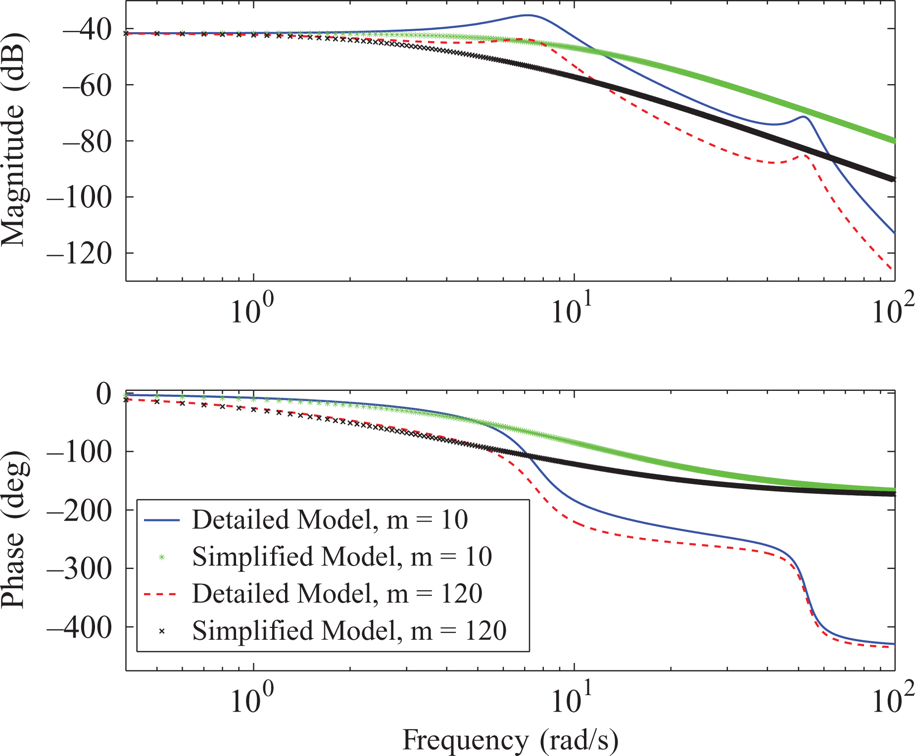
Bode plot in an open-loop control configuration:

Prototype of a four-degree-of-freedom intelligent assist device.
Conclusion
In order to achieve effective augmentation of human capacity using motorized mechanical devices, cooperation with the device must be very intuitive and safe for the operator. In this study, safety was related to vibrational disturbance, which could decrease the attention given to a task and thus lead to injury if the task were limited in time and involved risk. We have presented an analysis of the stability and intuitiveness of an assistive device using an admittance control scheme. The focus of our analysis was evaluation of models simulating pHRI. Four such models were developed and presented in detail, while experimental results provided insight into the ability of each model to simulate the interaction paradigm. The simple model found in the literature yielded functional results but was unable to reproduce suitable behaviors in response to certain situations encountered in practice, namely high-frequency underdamped response (vibration) when the virtual mass is low. A more elaborate open-loop model explained in part the behavior encountered in practice, namely the existence of a minimal virtual mass, but not its variation with virtual damping. Finally, based on our experience and experimental setups, we developed a more elaborate and improved closed-loop model. This model gave results very close to those obtained in our experiments and explained both the minimal virtual mass and its variation with virtual damping. This model leads to better comprehension of the mechanism under study.
In future work, we will use this model in simulations in order to design better systems. A design method for selecting the values of the virtual parameters will be proposed as well. This method will be based on a performance and perception study for evaluating the capability of human operators to manage an IAD for different tasks and in different situations as well as threshold amplitudes at which vibration with disturbance is perceived (visually and audibly).
Footnotes
Declaration of conflicting interests
The author(s) declared no potential conflicts of interest with respect to the research, authorship, and/or publication of this article.
Funding
The author(s) disclosed receipt of the following financial support for the research, authorship, and/or publication of this article: This work was supported by the Natural Sciences and Engineering Research Council of Canada (NSERC) (grant number DG 89715).
Appendix I: Prototype of a 4-DOF IAD
The robotic mechanism used for the experiments reported in this paper is the 4-DOF IAD prototype shown in Figure 18, allowing translation in all directions (XYZ) and rotation (θ) about the vertical axis.
42
The total moving mass is approximately 500 kg in the direction of the X axis and 325 kg along the Y axis. The payload may vary between 0 and 113 kg. The horizontal workspace is
Appendix II: Transfer functions for the improved model
The transfer functions (9) and (11) respectively for the open-loop and closed-loop versions of the elaborate improved model described in the section ‘Towards the development of an effective model’ are shown below. The transfer function for the open-loop model shown in Figure 9 is written as follows:
with
The transfer function for the closed-loop model shown in Figure 12 is written as follows:
with