
Abstract
Locating trapped or lost individuals is critical in search and rescue, directly impacting survival rates and responder safety. Rapid victim detection enhances response efficiency and enables timely rescue actions. Integrating advanced detection with mobile robots minimizes human risk, with snake robots offering a promising solution due to their flexible, modular design for navigating complex and confined environments. This article focuses on developing a snake-like robot (His Hands version-1/HH-I) for search and rescue missions. This article concentrates on two aspects of the robot: one is the design and development of the mechanism for traversal in a cluttered environment, and the other is establishing a fast communication system for sending victim detection information (based on a previously developed victim detection model) to rescue victims. The highlight of the work is the robust design made using CAD. The model was then developed and tested in real time, and most of the components in the prototype were built based on 3D printing and other in-house fabrications. The tracks on all four sides ensure self-recovery after rollovers, with a maximum slope climbing capacity of 40°. Experimental tests demonstrated a top speed of 6.8 cm/s on flat terrain and successful traversal on rubble, sand, and gravel surfaces. Victim detection is achieved using a transfer learning-based ResNet-50 model with 97.2% accuracy in an average detection time of 11.5 s. Then, the victim detection information is sent to the rescue teams’ mobile app with IoT using the IBM cloud and node-red.
Keywords
Introduction
Disasters, whether caused by nature or human actions, have devastating effects worldwide. Large earthquakes, fires, floods, aircraft accidents, tsunamis, building collapses, and other events can all result in significant life threats. Disaster management is essential to reduce or minimize the damage caused by these calamities. Recent mortality statistics from building collapses worldwide can be found in Ref. 1 This project falls under the disaster management cycle's preparedness and response phases, which involve being ready to face calamities with effective measures and responding quickly to save lives. The main focus of this project is to design and prototype an all-terrain robot that can navigate complex terrains. With the help of IoT technology over the IBM cloud, human victim detection information obtained from our previously developed model based on transfer learning 1 and custom-created datasets is communicated quickly to the rescue team. IoT-based IBM cloud and node-red allow fast and efficient communication with the rescue team. This work is a continuation of our previous works1,2 as part of developing a fully autonomous snake robot for earthquake rescue assistance.
This article focuses more on the design and development of the robot. The inspiration behind the choice of snake-like locomotion is explained with its biology first in the next section. With the basis of this biology, related snake robot developments are also explored, as well as their pros and cons. Section “The robot concept” discusses the concept of the HH-I snake robot with its salient features and detailed design. Finally, the results and discussions are discussed in section “Experiments, results and discussions.”
Snake robots: From biology to real robots
Snake robots, inspired by the intricate locomotion of their biological counterparts, represent a pinnacle of bio-inspired engineering. These robots mimic the versatile movements of snakes, enabling them to navigate complex environments with grace and agility.
In nature, snakes employ various locomotion techniques to traverse diverse terrains and obstacles:
Lateral Undulation: This involves creating rhythmic waves along the snake's body, which provides forward propulsion and maneuverability. Concertina Locomotion: Snakes anchor segments of their body and stretch forward, which is helpful in confined spaces. Sidewinding: Ideal for slippery surfaces, snakes lift sections of their body while moving in a winding motion. Rectilinear Locomotion: Snakes push and pull their body segments in a straight line in cramped spaces.
Snake-inspired robotic locomotion offers unique advantages.
When lateral undulation provides agility, adaptability to diverse terrains, and energy efficiency, concertina and sidewinding enhance maneuverability and obstacle negotiation, ideal for constrained spaces and slippery surfaces. In summary, snake robots blend biology and engineering to navigate environments from disaster areas to medical procedures. While challenges exist, such as design complexity, their potential benefits are transformative. Snake robots offer innovative solutions and promise a future where they can replace humans in hazardous environments due to their small size and adeptness in traversing rugged terrain. Readers can avail more details on biological snake locomotion from. 2
The concept of snake robots has a long history, dating back to the 1940s. These robots are characterized by their hyper-redundant, snake-like structure, which closely mimics the morphology of natural snakes. In 1946, J. Gray conducted a formative qualitative study on snake locomotion, categorizing the various types of snake movements.2 Subsequently, in 1972, Professor Shigeo Hirose achieved a significant milestone by developing the world's first snake robot (Figure 1) at the Tokyo Institute of Technology in Japan. 3

(a) World's first snake robot developed by Professor Shigeo Hirose 1 ; (b) a series of developed snake robots by Professor Shigeo Hirose.
Since that groundbreaking achievement, snake-inspired robotics has witnessed a proliferation of innovative designs and prototypes. The slender and elongated body with a thin cross-section of snake robots is well-suited for exploring narrow spaces and pipes. This unique design characteristic also enhances stability by distributing mass over multiple ground contact points, thus minimizing the center of mass.4,5 Consequently, snake robots exhibit more excellent stability than robotic locomotion types, such as legged or wheeled systems.4,6 Notably, snake robots excel in terrain adaptability, primarily moving along surfaces and utilizing the roughness of the terrain or obstacles to gain sufficient friction for forward movement without slippage. 7 This remarkable adaptability to diverse terrains and their inherent mechanical robustness makes snake robots well-suited for exploration in uncertain and challenging environments.
Many robot designs aim to mimic snake-like movements, but they vary in physical configuration and purpose. Some prioritize simplicity, while others incorporate redundancy. These robots can be categorized into undulating/passive skin snakebots and active skin snakebots. Undulating snakebots use wavelike joint motions for propulsion and consist of multiple segments. In contrast, active skin snakebots rely on wheels, legs, or tracks for movement and can have powered or unpowered joints, often called serpentine robots. A snake robot's structure consists of interconnected modules aligned linearly via joints, resembling a manipulator's linkage and joint system. These joints play a crucial role in determining the robot's relative head position, analogous to the end-effector position in a manipulator. Generally, most snake robots adopt a modular design, with their entire bodies composed of segments connected sequentially through these joints.
Based on the module's structure and how the segments are connected, snake robots can be categorized into 1-degree of freedom (1-DOF), 2-DOF, and 3-DOF modular structures. Two-DOF and three-DOF modules offer the advantage of reducing the number of robot modules while maintaining similar operating conditions. However, they are particularly beneficial in navigating 3D terrain, albeit at the cost of requiring more modules. The challenge lies in minimizing the cross-sectional size while ensuring sufficient output torque. To address this, two motors are often oriented orthogonally to achieve 2-DOF motion. However, this approach can result in bulkier modules due to the small diameter-to-length ratio. To mitigate this, modules are typically arranged in parallel with multiple other motors to reduce the cross-sectional size. The rotational axis is then transferred through worm gears or a combination of mechanisms. The choice of actuators for a snake robot is influenced by several factors, including the roughness of the operating surface, the minimum tunnel dimension, and the maximum gap to cross. There can be different actuators, such as DC motor/servo motors, pneumatic actuators, and hybrid actuators. A more detailed discussion of types of actions and different DOF joints is made in Ref. 1 Soft actuators like shape memory alloy (SMA), fluid elastomer actuators (FEAs), shape shape-morphing polymers (SMPs), and dielectric electro-activated polymers are used in more sophisticated applications, including snake robots and surgery.
Based on their methods of locomotion, existing snake robot designs can be divided into five categories: those with passive wheels (such as ACM III, ACM-R3, ACM-R5, AmphiBot I, AmphiBot II), those with active wheels (such as Koryu-II, GMD-SNAKE2, ACM-R4), those with active treads (such as OmniTread OT-4, OmniTread OT-8), and those that rely on undulations with vertical waves (such some snakebots can change their body to suit various activities and altering environmental circumstances because they are modular in design). The first snake robot (ACM), created by the renowned researcher Hirose in 1972, was 2 m long and had 20 single DOF joints.
Hirose created numerous snake robots, some with passive wheels (like the ACM-III and R5), some with active wheels serving as the primary actuators (like the ACM-R4), and a few with pneumatically powered joints (like the Slim Slime). Chowset of Carnegie Mellon University is another prominent pioneer in this area. He created several robots, including Greasefire, capable of 3D locomotion, such as swimming, climbing, and crawling, by altering joint configurations. For its snake robots, the University of Michigan used active treads and joints with pneumatic bellows designs (OT-8 and OT-4), which had a high propulsion ratio and flexible terrain adaptability. Later research investigated several approaches, including cable-actuated snake robots, modular snake robots using series/parallel elastic actuators, 8 and flexible snake robots based on smart materials.
Two versions of HITSZ-Snakebot were released with kinematic models for various gaits, such as creeping, rolling, and serpentine. The Guardian, a commercial remote-controlled ground-based surveillance and inspection robot, was created by Sarcos the year after. It features a live video feed, 3D mapping, and two-way communications for real-time data transferability in difficult conditions. This snakebot was released for commercial use and is priced at $60,000. The Kulko developers developed two innovative ideas for navigating ambiguous surroundings in 2020. The first method centered on detecting environmental contact forces using joint restrictions that had been measured. The second method utilized an embedded motor to rotate the cylindrical surface of each snake segment, producing propulsive forces that propelled the snake forward.
From comparison in Ref., 2 it can be found that different robots are designed with specific applications in mind, such as search and rescue, exploration, or industrial tasks. The choice of locomotion, actuation, sensors, and materials reflects the intended purpose of each robot.9–15 By equipping various sensors and tool modules, snake-inspired robots are developed from fixed-point operation in a single environment to autonomous operation in an amphibious environment. 16 Typically, the bodies of snake robots are created utilizing 3D printing or quick assembly with polycarbonate plastics, aluminum, or steel. For instance, the snake robot MAMBA has rubber-sealed components that offer waterproofing and enable operation in at least 2 m of water. A series of elastic actuator-based, low-cost, torque-controlled robots named Serpent was unveiled in 2019. Its 3D-printed modules are made of polycarbonate plastic using a manufacturing technique called fused deposition modelling (FDM). The elastic joint design has recently been enhanced, including adding a damper element, to handle larger traverse forces and improve the assembly. In summary, the diversity in the design of these snake-like robots, including their modes of locomotion, actuation methods, sensor integration, and fabrication materials, strongly supports the idea that these robots are purposefully designed for specific applications. More literature on sensors, perception control, modelling can be found in Refs.2,15–22
Snake robots have demonstrated significant potential in navigating complex environments such as disaster zones, underground tunnels, pipelines, and hazardous industrial sites. Their ability to maneuver through narrow, cluttered spaces where conventional wheeled or legged robots struggle makes them ideal for applications such as search and rescue, structural inspection, and medical procedures. Various research efforts have focused on improving locomotion efficiency, modular adaptability, and sensing capabilities. However, existing snake robots face key limitations, including high complexity in control, limited stability on irregular terrains, and insufficient real-time communication systems for remote monitoring.
Many prior designs rely on pneumatic actuation or sophisticated sensor networks, which increase system cost and maintenance requirements. Moreover, the integration of real-time victim detection with fast data transmission remains an underexplored aspect of rescue robotics. Some existing robots struggle with self-recovery after rollovers or fail to function effectively in mixed-terrain environments like rubble and loose sand. This study aims to address these gaps by introducing a novel low-cost, terrain-friendly snake robot that incorporates twisted string actuation (TSA) for efficient segmental motion, a robust multi-track system for enhanced stability, and an IoT-enabled fast communication framework for real-time victim detection and data transmission. Unlike previous models, our design eliminates the need for pneumatic components, reducing cost while improving maneuverability and deployment readiness in disaster scenarios.
This work focuses primarily on the development of a terrain-friendly snake-like robot traversing through uneven surfaces, assisting rescuers for search and rescue mission to detect victims trapped in collapsed building environment as a continuation of our previous work. 1
The robot concept
The HH-I (His Hands-I) snake-like robot is a bio-inspired, discreet, articulated, multi-segmented robotic system designed to enhance mobility in disaster environments. Drawing inspiration from the OmniTread robot, HH-I improves upon existing designs by replacing complex pneumatic components with cost-effective, easily manufacturable materials while maintaining robustness. Its architecture is tailored to navigate cluttered, uneven terrains, making it particularly suitable for search-and-rescue operations.
The robot consists of three identical segments, each connected by universal joints with 2-DOF, allowing flexible movement (Figure 2). Unlike biological snakes, HH-I moves in both forward and reverse directions, utilizing a track-based propulsion system that ensures stability and maneuverability across diverse terrains. Each segment is equipped with tracks on all four sides, driven by a single motor through a worm gear mechanism, guaranteeing continuous ground contact even when the robot flips. Furthermore, a TSA mechanism is employed for joint articulation, offering precise control with minimal mechanical complexity. An IoT-based communication system enables real-time data transmission, ensuring swift information relay to rescue teams. With a modular and scalable design, HH-I aims to provide affordable, efficient, and adaptable robotic solutions for disaster response.

(a) The outer body concept of the snake robot with all side track mechanisms to understand the segmented body concept; (b) a more intuitive and detailed CAD model of the prototype where a protective cover is provided between segments to avoid joint contact with the rubble.
The next subsection will describe a more detailed explanation of the above features under the aspect of the robot's development, starting with the design requirements and analytical calculations involved in the track and the TSA mechanism, followed by the communication system details.
Design details and requirements
This section discusses the details of each working part of the robot. The primary objective of the design was to create a robot with high adaptability, efficient movement on uneven surfaces, and the ability to transmit real-time data during rescue missions.
Drive train and the tracks for linear motion
This is the primary locomotive mechanism as well as the recovery mechanism when rolled over or flipped.
Recovery Mechanism After Rolling Over: One of HH-I's defining capabilities is its self-recovery mechanism, which ensures uninterrupted movement even after rolling over. Unlike conventional tracked robots that require external intervention for reorientation, HH-I's extra-wide tracks on all four sides allow it to regain orientation always. The multi-track propulsion system plays a pivotal role in maintaining locomotion across irregular surfaces. Even when flipped due to terrain instability, the robot continues its movement without disruption. Experimental trials on various terrains, including rubble, sand, and dust, have demonstrated HH-I's strong adaptability. However, track movement encounters resistance on debris with a characteristic diameter smaller than 14 cm, necessitating potential design refinements. To further enhance its usability in sandy and dust-prone environments, a dust-proof sealed version is currently under development.
The main hardware features of the multi-track propulsion system are the following:
Single motor drive—A single electric drive motor in the first segment provides rotary power to each segment through a so-called “drive shaft spine” that runs through the whole length of the robot to actuate the tracks Driveshaft spine—Separate long shaft for each segment with a motor interconnected via a universal joint in the body's center axis transfers the single motor drive to all the segments All side tracks—DC motor with worm gear arrangements helps the motor power to be equally distributed to all four sides to provide equal acceleration. The main objective of this design is to enhance the coverage of the entire robot body by using moving tracks. This feature is crucial as a serpentine robot's slim and elongated body can easily roll over challenging terrain, making it difficult to get back on its feet immediately.
The single motor drive, drive shaft spine, and all side tracks contribute to the drive-train track mechanism. Two universal joints link three stiff shafts to form the drive shaft spine. The universal joints are situated between two neighboring segments or two adjacent shafts. There is a worm on each shaft segment. Figure 3 depicts how four worm gears (identical) drive the tracks with a single motor-driven drive shaft. Each worm gear drives the track rollers through a belt. To compensate for the torque, the gear ratio is 2.5. Two ball bearings hold the drive shaft at the gearbox's ends, maintaining the gearbox's good tolerances. The universal joint is the only thing holding the other end of the drive shaft in place. If the segment's construction warps under heavy loads, not restricting the shaft at three spots prevents the driveshaft from flexing excessively (Figure 4).

(a) Mechanism of the track drive with worm gear supported by a single motor drive. All four faces of the robot are covered with track and pulley arrangements (only the upper face is shown here). (b) Insight of the mechanism of the track drive with worm gear supported by a single motor drive. The rotary motion from the drive motor to other segments through segments of long shafts connected through universal joints.

Transferring the rotary motion from the drive motor to other segments through segments of long shafts connected through universal joints.
The key advantages of this drive train system are:
Full Coverage with Propulsion Surfaces: The robot is less likely to stop or slow down, as each side is equipped with tracks. Even in rollover situations, motion is maintained. High Traction and Torque Transfer: The broad track width and optimized grouser pitch enhance traction on various terrains, reducing the chance of slipping.
The tracks were manufactured in-house using a combination of 3D-printed molds and silicone gel, reinforced with glycerin for durability. Maintaining a large roller diameter and increasing the number of engaging teeth helped improve torque transfer and reduce the risk of track detachment.
Analytical calculations for the track mechanism
The torque required for movement on a horizontal plane was calculated considering gravitational forces, rolling resistance, and tractive forces. The total force acting on the robot's track can be expressed as sum of these three:


Analytical torque calculations.

Twisted string actuation mechanism for joint actuation
This is a separate joint actuation mechanism for steering using stepper motors. The universal joints placed between each segments establish the system's connectivity and actuation mechanisms. TSA drives these joints, necessitating two separate TSA mechanisms for each universal joint. The joint's flexibility allows for a range of motion from at least 30° to 40° in four principal directions: upward, downward, and side wise. Nylon wires link four stepper motor shafts parallel to the adjacent segment, facilitating clockwise and counterclockwise rotations (Figure 5). Steering the robot involves a nuanced interplay of motor actions. To execute a right turn, two motors on the right side rotate clockwise, reducing the distance between segments. In contrast, simultaneously, two left-side motors rotate counterclockwise to limit the turning angle. Steering in the opposite direction follows a similar principle. The clockwise rotation of two top-corner motors achieves the upward motion of the robot's first segment, whereas the counterclockwise rotation of two bottom motors results in downward movement. The concept of side-wise motion with the TSA is depicted in Figure 6. Initially, the segments are aligned at the home position where joint angle deflection is zero. When the motor starts rotating, the string twists from zero to maximum contraction on the right and maximum expansion on the left, making the first segment displace toward the right. Likewise, the left and up-down motions are achieved. With this, efficient and versatile robotic maneuverability is achieved at less cost, making this TSA mechanism the salient feature of the work.

TSA mechanism: CAD model of the TSA mechanism where the interconnecting rods act as linear actuators, which in the prototype is replaced with a twistable nylon string to control the linear movement.
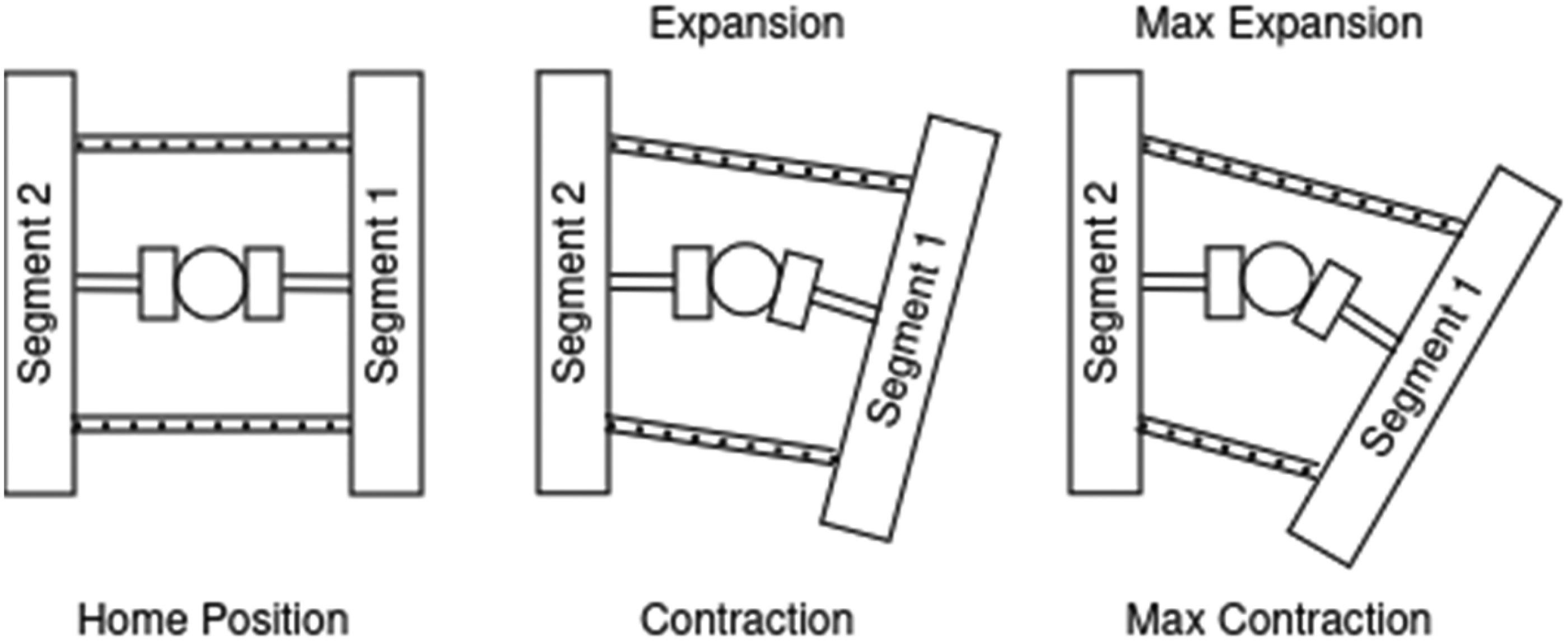
Working of TSA for shifting one segment to the right.
Based on the above design and analytical study, to drive a multi-segmented articulated snake-like robot weighing 5 kg with a speed of 10 cm/sec using the designed all-side tracks controlled by a single motor drive, 1.2 Nm torque with a gear ratio of 2.5 is required to climb a slope of 40°. Similarly, total power in lifting plus linear motion is obtained to be 0.966 W, considering the potential energy. Therefore, DC stepper motors with a power rating of 1.2 W are required.
Sensor information and communication
Based on our previous work 2 for identifying human victims in a collapsed building environment, a robot brain is created to identify trapped victims with the developed deep learning model. The robot is capable of collecting camera information and detecting victims. Once a victim has been detected, the information can be sent to the rescuers, along with their location and environment. The optimal Resnet-50 model has been tested, and the accuracy obtained for victim detection is 97.2% in less than 2 s. Hence, the developed model was tested to be more accurate and efficient than any existing image processing algorithms. For fast robot communication with the rescue team, IBM Cloud and node-red were utilized. The information sent using the node-red was displayed at the mobile app end using the MIT app inventor. Figure 7 depicts the workflow. Let's look into the communication part in a little detail.

(a) The concept of communication from HH-I to rescue teams through node-red after integrating image processing with cloud storage (b) its real implementation with HH-I.
The system combining image processing and cloud storage with a Raspberry Pi is divided into two main parts. The first part, the front end, includes various components such as the DHT11 sensor, Neo 6 m GPS module, and a microphone, all linked to the Raspberry Pi to collect and transmit data to the IBM Cloud. Additionally, a camera module is incorporated, sending its data wirelessly to any device on the same local network. To facilitate this, the M-jpg streamer, a command-line tool, transfers frames from an input source to an output destination. The live feed from the webcam can be viewed on applications like Chrome or VLC through an IP-based network, where the camera generates Jpeg images and delivers them directly to the viewer. This stream supports image classification on any device sharing the Raspberry Pi's network. After processing, the resulting images are uploaded to IBM Cloudant, while sensor data is directed to Node-RED.
For the front end, a Raspberry Pi with 3GB of memory serves as the central processor, paired with four devices: a microphone, DHT11 sensor, camera, and Neo 6 m GPS module. The setup operates on a Raspberry Pi 4 running the latest Raspbian OS Linux version, equipped with all required software to support the connected devices. Once the system is fully connected, Python scripts handle data collection from the sensors, sending this information to the IBM Cloud and integrating it into the Node-RED workflow, as illustrated in Figure 8. The data is transmitted in JSON format to the IBM Cloud using credentials established in the database. Each time new data is gathered, it is forwarded to the Node-RED flow for future use and to provide real-time environmental updates, which can be viewed both in the cloud and on a mobile application.

The node-red flow.
The information collected is transmitted to an MIT-developed application, which organizes it into specific categories for users to view the final results. This app automatically retrieves real-time sensor data from the Raspberry Pi. On the backend, data from the Raspberry Pi 4 supports two key tasks. First, image processing is performed using an enhanced ResNet-50 model, which analyzes the live feed from the Raspberry Pi's camera. Second, all processed data is stored in the cloud, allowing access through Node-RED alongside basic operations like sorting, checking, and converting microphone input into text. The finalized data is then sent as a message payload to the MIT app, enabling users to view it on any connected device.
The system employs the refined ResNet-50 model to identify human presence in the camera feed by comparing features of stored frames with the current frame captured. This analysis determines the objects within the frame, and for clarity, the system outlines detected objects with a rectangular box using the same ResNet-50 model. The resulting data is uploaded to IBM Cloudant as a JSON file, authenticated with a token. In the image processing workflow, the camera feed is saved as a frame and matched against a dataset within the system. When an object, such as a face, is recognized, the frame is captured and sent to Cloudant, where it is merged with other sensor data in Node-RED. Node-RED, a flow-based development tool, connects various hardware, APIs, and services like fast2sms to build event-driven applications. Although IBM offers a default Node-RED service, it is provided as a third-party tool rather than an in-house solution.
Sensor data, including temperature, humidity, and GPS coordinates, is transmitted directly from two distinct Python scripts, each with a unique identifier included in the JSON file. This data is received by an IBM IoT node configured with the necessary credentials and stored in the message payload, as depicted in Figure 8. Since the system uses two Python scripts, identical payload names could cause confusion on the receiving dashboard. To prevent this, a switch node separates the data based on the unique identifiers in the JSON file. This organized data is then passed to subsequent nodes for straightforward use without complications.
The data received from the system is separated into three different processes:
Temperature and humidity values are published as an HTTP URL using HTTP response nodes, which can be accessed later in the MIT app. Set of data, including latitude, longitude, and altitude, along with the message received from the microphone after speech-to-text conversion. Another set of GPS values is added in a JSON and published as another HTTP response URL (accessed later in MIT app inventor).
A JSON file stored in the IBM Cloud includes a link that points to the latest image captured and processed, which is saved in an IBM bucket. To retrieve the most recent image from Cloudant, a sort node is employed, organizing the data in descending order based on a “count” variable. This variable increases each time a new image is taken and sent from the image processing section, allowing the system to track the count and identify the latest image.
The system also incorporates a paid service called fast2sms, integrated into the microphone process through an HTTP request node. This service generates an SMS message containing selected data as text, which is sent to a registered phone number. If the data fails to reach the MIT App Inventor, an additional safeguard is provided. MIT App Inventor is a free, web-based platform for creating applications, originally developed by Google and now managed by the Massachusetts Institute of Technology. Its primary benefit is that it requires no coding expertise, relying instead on a block-based system and a drag-and-drop graphical interface that is simple and user-friendly. Once an app is designed, it can be compiled for operating systems like Android and iOS.
Regarding the Tetherless Operation (Electric Power and communication with the team, it is necessary to note that the robot is not supplied with resources through a tether: electric power, control signals, and wireless communication were supplied on-board to make the robot tetherless. Four LiPo (Lithium Polymer) batteries of 2.2 ampere hour are the power source for the robot. That is, an 8.8-ampere-hour battery is equipped in the robot. In total, all electronic components draw 7.8 Amps of current. The maximum current consumption capacity of the robot is more than that. The robot can be operated continuously for at least 1 h and 10 min. The human detection and communication part is not included in this; they were tested separately.
Experiments, results and discussions
This section starts with the robot's hardware assembly and development followed by the real-time calculations of the mechanism including the materials and matrices for the performance evaluation. Finally goes into the real-time testing of the communication system with IBM cloud using the robot (i.e., communication of the robot to the mobile app).
Robot development and hardware assembly
The development of HH-I combined innovative design with in-house fabrication to create a cost-effective and robust solution. The track mechanism, a vital component of the robot, enables it to traverse diverse terrain while maintaining stability. Each segment of the robot is equipped with tracks on all four sides. A single motor drives these tracks through a worm gear mechanism, which transfers rotary motion to all the pulleys. This configuration ensures that the robot can recover its orientation and continue moving even after a rollover. TSA is a significant innovation in the robot's design. It offers an efficient and lightweight solution for joint actuation, where twisting the strings causes them to contract and pull the connected joints. Two TSA mechanisms were used for each universal joint, providing a wide range of motion. Nylon strings were selected for their strength and durability, ensuring reliable performance.
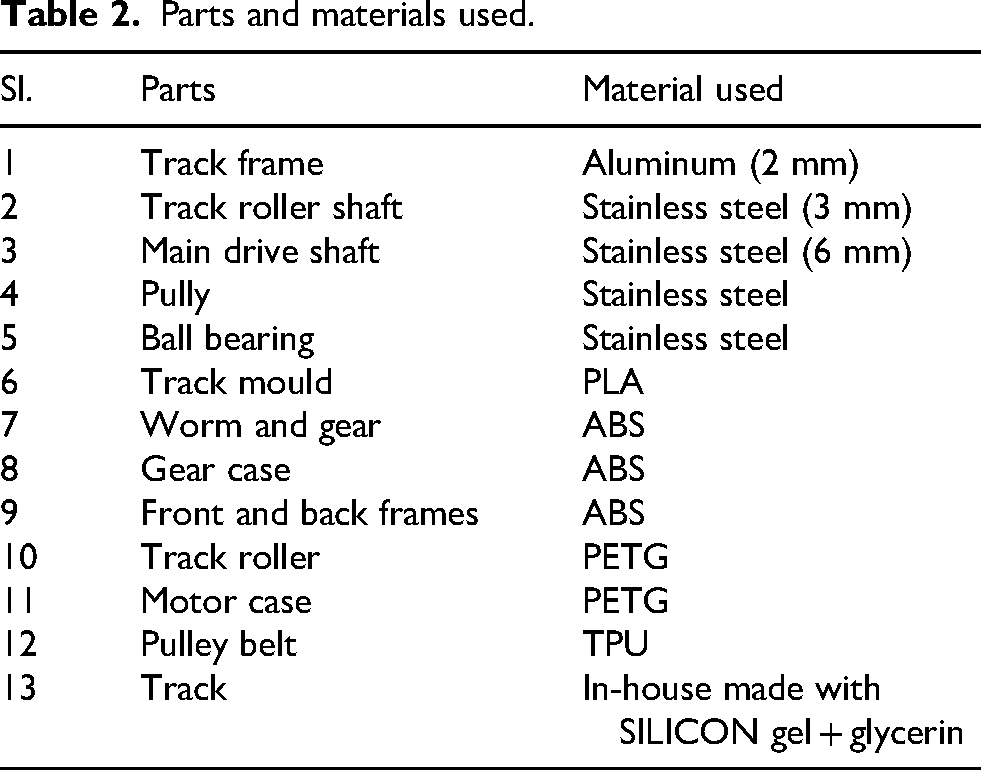
The CAD model is designed using Solid Works software, and the assembly consists of 1500+ individual parts. Most solid-work model parts are 3D printed in the FDM printer with PLA (polylactic acid), ABS (acrylonitrile butadiene styrene), TPU (thermoplastic polyurethane), and PETG (polyethylene terephthalate glycol) materials. The material is selected based on each part's structural, physical, and location requirements. Besides these parts, aluminum strips, steel ball bearings, and steel rods are used for structural stability and friction reduction. All 3D-printed parts are assembled as segments, and three segments/compartments are fabricated. One of the major features of HH-I is that the track is completely in-house made by combining silicon gel and glycerin in a 3D-printed track mould. This approach not only reduced costs but also allowed for customization to meet specific requirements. The first segment houses (Figure 9) the drive motor (BLDC), motor driver, camera module, and compute module (Raspberry Pi 3B+). The second segment houses a power distribution unit, four stepper motors for steering the adjacent segment, four stepper drivers, and an Arduino Mega 2560 microcontroller for actuation. The third segment houses four stepper motors for steering the next adjacent segment, four stepper drivers, and four LiPo (lithium polymer) batteries of 2.2 Ah. Each segment has a 3D-printed worm-gear mechanism to transmit power from the main drive motor in the first segment to the four side tracks of all the segments. A universal joint in the middle of two adjacent segments transfers the rotary motion from one segment to the following segment. Table 2 indicates the parts and materials used in the component fabrication.

The prototype of the snake robot mechanism.
Parts and materials used.
Real-time calculations of the mechanism
Materials and methods for robot evaluation performance: The robot's performance was evaluated in a controlled environment designed to simulate debris-filled and inclined terrains. The evaluation focused on terrain adaptability, joint actuation precision, and communication system reliability. This section discusses the real-time results obtained while the robot traverses under different slopes and lifting.
Torque while moving on different plane angles
This section briefly analyses torques in the drive system. This is the largest legitimate load to be expected under normal conditions, denoted as Ftotal. Of course, even larger loads may develop if a track becomes jammed. Such overloads can cause part breakages. For the analytical calculations, the assumptions taken were: weight = 5 kg, speed requirement = 0.1 m/s (10 cm/s). Whereas the actual weight changes to 4.75 kg in the testing while the speed obtained was 0.68 m/s on flat terrain assumption. Equation (1) was used for both the analytical and practical torque calculations. In experimental analysis, the motor speed (input speed) was used to find the output speed and thereby the acceleration leading to the other parameter calculations to obtain the practical speed and torque. Considering the robot of mass m climbing a slope of α angle upwards, the total force acting on it could be the sum of the rolling force, tractive force, and gradient forces (mg.sin θ) acting on it (as in Equation (1), see Table 3). Robots traversing a slope of 5° and on a dusty and gravel terrain are shown in Figure 10.

(a) The robot climbing a 50 slope, (b) robot moving on dusty terrain, and (c) robot traversing on a gravel surface.
Real-time results.

TSA mechanism
Before conducting any experimental studies, the snake robot is positioned in its home position. That is all segments are lined up in a straight line. Initially, every adjacent TSA is equally twisted. This gives enough expansion (relaxed) or contraction (high tension) of the string. For effective steering of the segments, the angle or distance between segments needs to be identified first. Initially, IR and ultrasonic sensors were tried for the experiments to calculate the distance. However, the sensor is too big to be mounted for testing, and it points away from the joint after steering. As feedback sensors are not used due to limited spacing, the twisted count is used instead. Simple rulers and protectors are used to observe the values. However, in inclined or slopy regions, the actual distance fluctuates, and there is a trade-off. Hence, only flat terrain readings were focused in the TSA experiments. The angle from the driving shaft and the distance between the two segments are recorded for every five consecutive twists (see Table 4). For example, how much should the corresponding TSA expand or shrink to move a segment to a side, and for this, how much should the motor rotate?
Experimental calculations of the TSA mechanism.

Initially, the segments are aligned at the home position where joint angle deflection is zero. When the motor starts rotating, the string twists from zero to maximum contraction on the right and maximum expansion on the left, making the first segment displace toward the right. Likewise, the left and up-down motions are achieved. Therefore, based on the results, the robot specifications have been summarized in Table 5.
Robot specifications.

Tetherless operation (electric power and communication with the team: The robot is basically a snake-like robot mechanism that is capable of traversing uneven terrains. It is not supplied with resources through a tether: electric power, control signals, and wireless communication were supplied on-board to make the robot tetherless. 5 LiPo (Lithium Polymer) batteries of 2.2 mAh are the power source for the robot. That is, 10.1 mAh of battery is equipped in the robot. In total, all electronic components draw 9.2 Amps of current. The maximum current consumption capacity of the robot is more than that. The robot can be operated continuously for a minimum of 45 min. The human detection and communication part is not included in this, and they were tested separately.
Real-time testing of the communication system with IBM Cloud
Camera data were successfully sent to the local host with the help of Raspberry Pi 3B+ and were found to be compatible with the robot's power consumption (numbers) and size. Figure 11 shows the real-time testing of the human victim detection approach (HVDA) with real and artificial human body parts (here in the figure, a real hand, and a glove are used) with the robot. Whereas Figure 12 depicts the MIT App layout. It is a simple application designed to access and receive data when it is connected to the IBM Cloud. The data is accessed through HTTP requests published from the node-red flow that receives the current information of every device connected. A section for every information is assigned, and when data is published, the data will be displayed in their respective columns. The identified victim's image and the mini-map location can be displayed in real time with the help of the MIT app inventor within a maximum of 11.5 s. Tables 6 and 7 present the real-time performance evaluation of the HVDA using live feed and pre-collected images, respectively. The analysis provides insights into execution time variations, accuracy levels, and system efficiency under different conditions. Table 6 highlights the execution time per frame and accuracy of the HVDA when processing live feed data. The results indicate that different body parts exhibit varying detection times, with the head taking the longest (11.5 s) but achieving high accuracy (96.27%), while the upper body has the shortest execution time (5.65 s) with similar accuracy (96.23%). The hand glove shows the lowest accuracy (85.83%), suggesting that artificial objects might introduce classification challenges compared to real human body parts. The variation in execution time is likely influenced by the complexity of the object features and the processing demands required for distinguishing body parts. Table 7 evaluates the HVDA performance when using images not included in training. The execution time varies from 2.1 s to 8.35 s, depending on the number of detected objects and their complexity. The system achieves a high detection accuracy (above 83%), with the best accuracy (97%) observed in scenarios where a single object is detected. However, when multiple objects (two classes) are present, the accuracy drops to 83.55%, likely due to increased computational complexity and possible misclassification. The reduced execution time in some cases (e.g., 2.1 s) suggests that detection is faster when fewer objects are present in the frame.
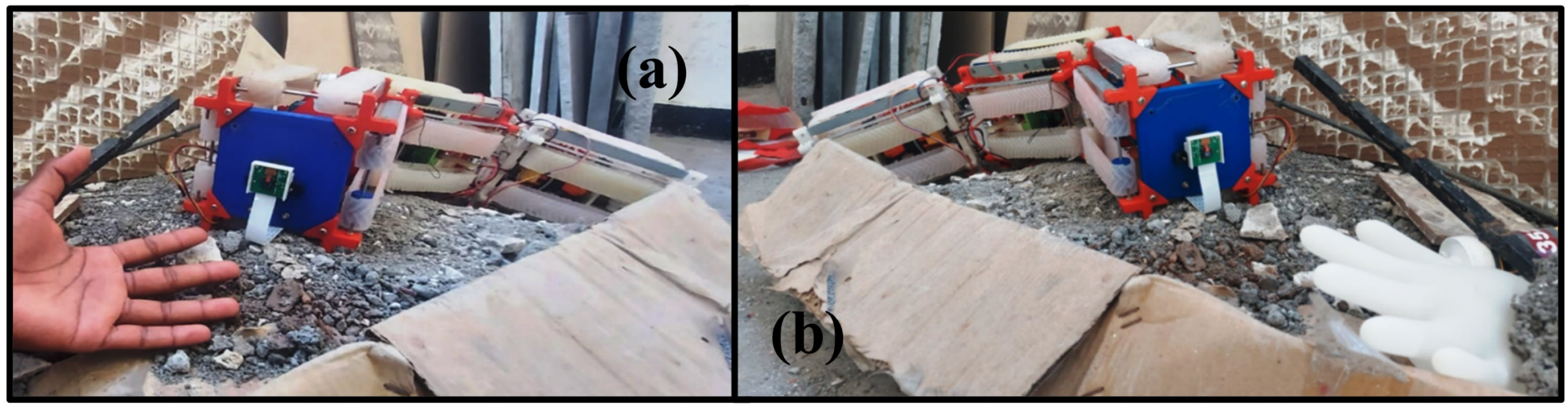
Transferring real-time testing of the HVDA with: (a) a real human hand and (b) a glove.
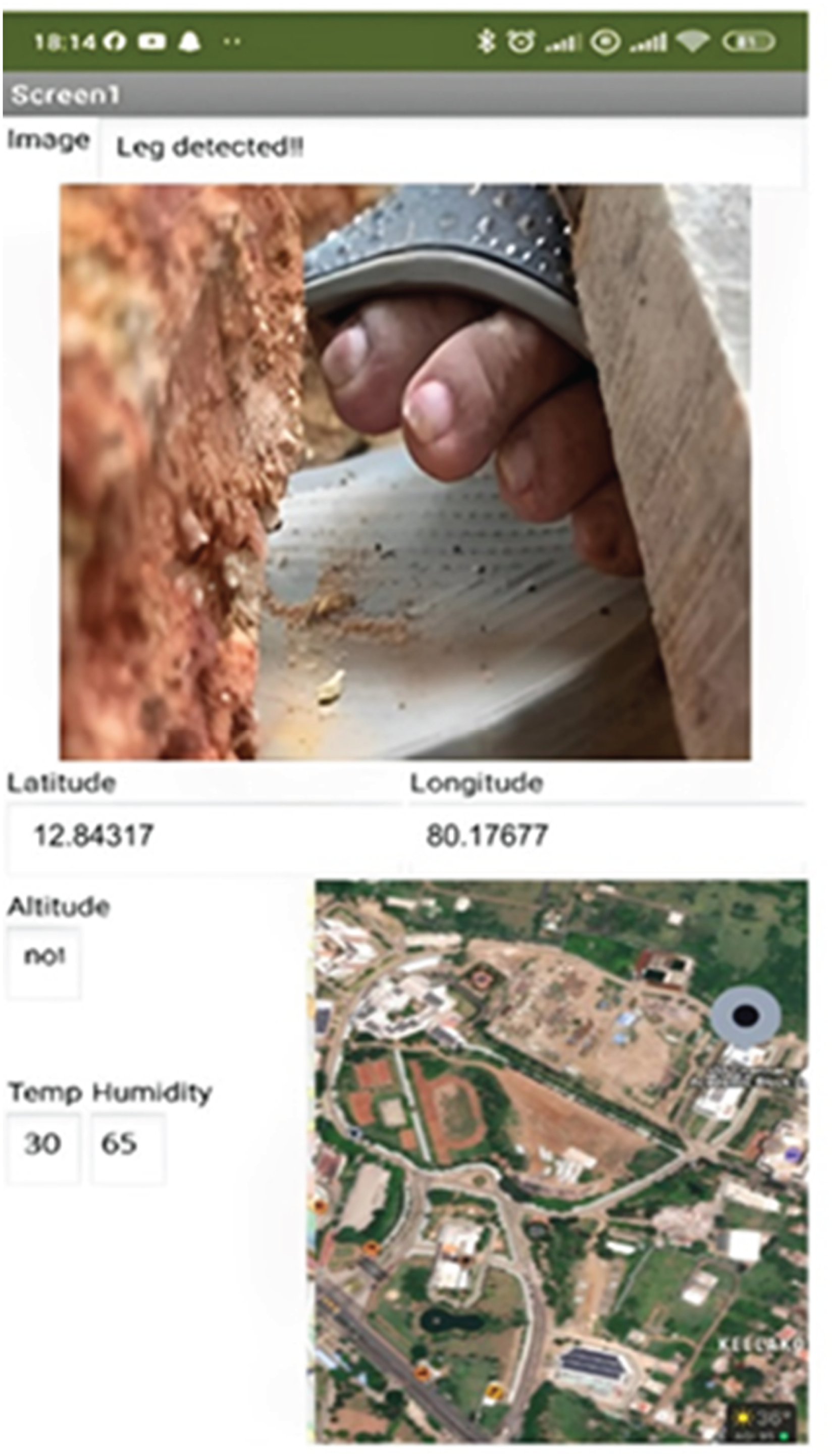
The MIT app inventor screen with information received as leg detected along with GPS and temperature information.
HVDA' performance using live feed.

Performance of the human victim detection approach with images taken during data collection but not used in training (HVDA).

The live feed processing is found to be slower than pre-collected images, indicating the added computational load of real-time data acquisition and transmission. Whereas, the accuracy remains high in both cases, demonstrating the reliability of the detection approach, although artificial objects (like gloves) slightly reduce performance. However, processing multiple objects increases execution time and slightly reduces accuracy, suggesting potential areas for optimization in the detection algorithm. Overall, the HVDA shows strong performance in real-time victim detection, with minimal delays (maximum 11.5 s) and consistently high accuracy, making it a viable solution for emergency response and search-and-rescue applications.
Performance of IoT communication in rescue scenarios
The IoT-based communication system plays a crucial role in ensuring real-time data transmission during rescue operations. However, certain performance aspects require further discussion:
By addressing these aspects, the proposed IoT communication system can enhance the effectiveness of the rescue operation, ensuring reliable and efficient victim detection and reporting.
Conclusion
We developed a snake-like robot mechanism for traversal in a cluttered environment and a fast communication system to connect with the rescue personnel while assisting rescue teams in identifying victims partially trapped in a collapsed building. The unique and innovative features of the robot come under two parts of the work: the design features of low-cost prototype development and the development of a fast communication system, specifically:
The joint actuation with the TSA mechanism. Extra-wide tracks on all sides surround the body to continue motion even after rollovers. IoT-based fast communication for human victim detection from a robot to a mobile app.
Most prototype parts were created using 3D printing and other in-house fabrication techniques. The single motor-driven all-segment track mechanism and the TSA for the joint control were notably performing well. The mechanism performed well in different slopes ranging from 0 to 40° and terrains. The robot is not supplied with resources through a tether: electric power, control signals, and wireless communication were supplied on-board to make the robot tetherless. Four LiPo batteries of 2.2 mAh are the power source for the robot. That is, 8.8 mAh of battery is equipped in the robot. In total, all electronic components draw 7.8 Amps of current. The maximum current consumption capacity of the robot is more than that. The robot can be operated continuously for 45 min on flat terrain.
The robot performs particularly well on non-smooth terrain, such as rubble and sandy and dusty environments for which it was originally designed. However, it performed less well on terrains covered deeply by debris with a characteristic diameter smaller than 14 cm. We also believe we can design a dust-proof, sealed version of the robot, which would likely fare much better in sandy terrain.
Based on our previous study, 1 the transfer learning-based, pre-trained ResNet-50 model detects the trapped human from the image captured by the robot camera. The victim detection data is then transmitted to the rescuers’ mobile app via IoT using the IBM cloud and node-red. The accuracies of the victim detection were obtained between 85.83 and 96.27 in real time with an overall execution time of 11.5 s (maximum), which is quite an accurate, fast, and promising result.
This system can help in faster and more efficient rescue missions by enabling rescuers to focus only on rescue operations and not waste time searching for victims. In addition, the mobile application created can visualize the victim's information, aiding the rescue in time and effort.
Limitations
As mentioned, snake-like locomotion is a highly promising type with infinite challenges. The mechanism concept we tried can traverse flat, slippery, sloped, rubble-filled, and sandy terrains and lift the front segment. That was our primary goal for the mechanism. Making it autonomous has not yet been touched. Precise control of the mechanical prototype was a bit challenging. Further focus needs to be given to controlling autonomy and miniaturization.
Future development and potential expandability
The proposed snake-like robot, HH-I, serves as an innovative rescue assistance mechanism. However, several advancements can be explored to enhance its functionality and expand its application scope. Future work could focus on autonomous navigation, integrating advanced control algorithms, reinforcement learning, and enhanced sensor fusion to allow independent decision-making in unknown environments. The miniaturization of the robot using advanced materials and compact actuators could enable more effective traversal in confined spaces, making it suitable for surgical applications or pipe inspections. Additionally, the modular adaptability of the robot can be improved, allowing configurable segments that adjust based on terrain conditions or mission requirements.
Moreover, integration with swarm robotics could enable multiple snake robots to collaborate in large-scale disaster scenarios, sharing real-time victim detection data for a coordinated rescue effort. The current IoT-based communication system can be further enhanced with edge computing, ensuring real-time data processing even in connectivity-compromised environments. Lastly, hybrid locomotion techniques, combining wheeled, legged, and serpentine motion, could be explored for better maneuverability across mixed terrains. These advancements would position HH-I as a versatile and scalable robotic system for diverse search and rescue applications.
Footnotes
Funding
The authors disclosed receipt of the following financial support for the research, authorship, and/or publication of this article: This work was supported by Vellore Institute of Technology, Chennai, Tamil Nadu, India and the Department of Science and Technology-Tamil Nadu State Council for Science and Technology (DST-TNSCST) under Award TNSCST/STP/PRG/17/2019-2020 to develop an autonomous snake robot for earthquake rescue applications.
Declaration of conflicting interests
The authors declared no potential conflicts of interest with respect to the research, authorship and/or publication of this article.
Data availability statement
The data supporting this study's findings are available from the corresponding author upon reasonable request.