
Abstract
This paper introduces a new development of a two-wheeled robotic wheelchair (TWW), designed to address the challenges of personal mobility for the elderly and individuals with lower limb disabilities. By incorporating a sliding seat mechanism and motorized support legs, the TWW enhances stability, comfort, and accessibility in narrow or uneven environments. Notably, the TWW has a minimum turning radius of 0.372[m], enhancing convenience in confined spaces. A dynamic inversion-based motion planner is developed to provide smooth and stable driving experiences by accurately converting user inputs into optimal trajectories. Furthermore, the system prioritizes safety through real-time fault detection, ensuring reliability in various scenarios. Experimental results validate the system’s enhanced posture stability and safety, highlighting its potential for a wide variety of applications in daily mobility and rehabilitation support.
Introduction
Common powered wheelchairs by electric motors are beloved as a convenient means of mobility by the elderly and individuals with lower limb disabilities. Typical powered wheelchairs such as Johnson and Aylor, 1 Levy and Chow, 2 Seki et al., 3 Wang and Chiang, 4 Cooper et al., 5 Imasen 6 have been using two active wheels and additional passive casters, to offer the advantage of stable seating. However, these designs often result in bulky wheelchairs that occupy substantial space when turning, which leads many users to report difficulties in navigating narrow spaces and uneven ground in outdoor environments. 7 This issue fundamentally highlights the shortcomings of conventional wheelchairs that require improvement.
There have been efforts to modify or refine the typical powered wheelchairs to overcome these drawbacks. Some notable examples are: attaching small wheels or utilizing mecanum wheels to existing powered wheelchairs to reduce the turning radius,8,9 adding steering devices to facilitate maneuvering in tight spaces, 10 lifting the casters with inverse pendulum control to improve accessibility over bumps, 11 and utilizing distance sensors to climb stairs. 12 Nevertheless, conventional powered wheelchairs face fundamental limitations, including reduced terrain accessibility and spatial inefficiency. To overcome these limitations and drawbacks, we present, in this paper, a novel two-wheeled robotic wheelchair (TWW), with enhanced stability and comfort by adding an additional mobility in the seat, as shown in Figure 1, yet having compact form factor for better agility and maneuverability. Concerning the two-wheeled mobile systems, studies have focused on controller designs,13–18 disturbance compensation,19–22 and trajectory planning,23,24 to cope with the fundamental requirements such as balancing and stabilization issues caused by the inherently unstable nature of the main body. Not just being left as autonomous robots, the two-wheeled mobile platforms have been developed as a type of personal mobility. For example, Segway S Plus 25 and Toyota’s Winglet 26 were used as a personal mobility system, allowing a person to ride with the standing pose. Genny Zero 27 and Omeo 28 allowed the user to ride while seated. However, these two-wheeled mobile platforms built for the personal mobility are not suitable for individuals with lower limb disabilities or seniors, who may often find it difficult to drive with because of unsafe behavior when getting on and off or unnatural rider’s upper body swing under acceleration and deceleration.

Prototype of two-wheeled wheelchair.
Rather recently, some two-wheeled mobile platforms were incorporated with additional mobilities and actuators to help balancing and posture control. IBOT 29 utilized multi degree of freedom (DoF) wheel clusters so posture control and stair climbing became possible. However, due to the dual revolute motion around the wheels, unwanted vertical up-down movement was observed during the posture control for the navigation. S-POD 30 was designed as a personal mobility possessing a sliding mechanism between the base and the upper body, to maintain a stable horizontal posture during motion. But, it was not designed for daily indoor-outdoor use nor suitable for the elderly and individuals with disabilities because of its large egg-shaped seat and lack of stable parking systems on the slope. Tomokuni and Shino 31 introduced a two-wheeled inverted pendulum personal mobility with active wheel legs and a seat slider to enable height and roll posture control. Nevertheless, its leg links required large actuators to lift the entire body and more importantly it became more difficult to ensure the strict safety, by which their mobility system would not seem reasonable for practical uses. Hirata and Murakami 32 used a motorized backrest on a two-wheeled mobile platform to maintain its horizontal posture. But it created an uncomfortable upper body swing during motion. Nikpour et al. 33 proposed a mechanism that utilizes additional suspended links under its seat to passively balance the two-wheeled system, but their design did not seem generally acceptable due to requiring bothersome side pendulums.Based on the observation that previous developments of two-wheeled personal mobilities did not intend for or were not adequate for the elderly and individuals with lower limb disabilities, we started developing a dependable two-wheeled wheelchair, as shown in Figure 1, that is suited for daily use in indoor and outdoor all around environments. The developed robotic wheelchair offers a comprehensive solution addressing the multifaceted needs of users with mobility impairments. The sliding seat mechanism not only ensures postural stability but also enhances the rider’s comfort during transitions, such as navigating inclines or sudden stops. The motorized parking legs provide reliable support during boarding and disembarking, catering specifically to the needs of individuals with lower limb disabilities. Moreover, the stable dynamic inversion method transforms joystick inputs into smooth and predictable trajectories, delivering both control competency and operational consistency. Lastly, the integrated safety monitoring architecture proactively identifies potential risks, ensuring enhanced security for users in real-world scenarios. These innovations collectively redefine the standards for safety, comfort, and adaptability in powered wheelchairs.
This paper is organized as follows: the “System description” section addresses the hardware and software components and features of the developed TWW system. The “Control strategy” section presents the control architecture, with a focus on the practical control strategies. The “Experimental validation” section gives experimental results and concluding remarks are made at the end.
System description
In mechanical design point of view, the developed TWW, shown in Figure 2, possesses enhanced features, including its compact design form factor by integrating customized mechanical and electronic components such as an added seat sliding mechanism allowing for an additional DoF and motorized front/rear parking legs for passive standing.

Hardware modules of the prototype of the two-wheeled robotic wheelchair (TWW).
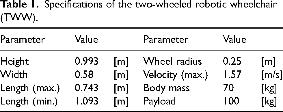
Figure 2 shows three main modules (chair, base, wheels) and their assembly. The assembled prototype has outer dimension of 0.993(height)
Specifications of the two-wheeled robotic wheelchair (TWW).
The chair module of the TWW was designed to enhance the riding comfort of the user. It includes the seat base, back support, and foot support. And, there is an ’X’ shaped mechanical cushion under the seat base that reduces road vibrations. A detachable joystick is placed at the end of the right armrest of the chair that controls the navigation speed and yaw rate.
The base module of the TWW includes a seat slider a two wheel drive axle, and motorized parking legs. The seat slider works as a linear actuator that moves the chair module back and forth with the stroke range of
Comparison of key performance.

In the aspect of the electronics, the TWW contains power module, drive module, sensor module, and control system. As the main power, we use a battery of 72VDC to generate wheel-driving and computing power. The drive module consists of two 1.5[kW] motors for driving the wheels, one 400[W] motor for the seat slider, and four 100[W] motors for the parking legs. (Refer to Table 3 for important specifications of each actuator.) For the sensors, we use one single-axis gyroscope, CRH02, and two dual-axis accelerometers, CAS212, both from Silcon Sensing Inc. Finally, the main controller was implemented on an industrial PC (Intel CPU i5, 4 cores), with the EtherCAT real-time communication. Please refer to Figure 3, for the overall system diagram illustrating the connectivity between devices.

Two-wheeled robotic wheelchair (TWW) system interface.
Driving actuator specifications.

Control strategy
In this section, we address the mode switching control from parking state to two-wheel mode or in reverse, as well as the driving control of the TWW for purposeful navigation.
Mode switching control
Parking mode and Two-wheel mode
Parking mode refers to the situation when the TWW is stationarily waiting for boarding or disembarking of the rider. In this mode, the four parking legs are fully lowered to the ground, the two-wheel motors are locked by the magnetic brakes, and the seat slider is positioned to yield the static equilibrium. On the contrary, two-wheel mode refers to the dynamic mode in which the TWW is actively balancing and navigating through the environment by controlling the two wheels and seat slider. The four parking legs, in the two-wheel mode, are fully raised, so that only two wheels make contact with the ground.
Smooth transitions between these two modes are critical to prevent tip-over or loss of balance. Mode transitions require synchronized activation and deactivation by considering the distance margin between the parking legs and the ground. Figure 4 illustrates the distance margin between the ground and the caster wheel under each parking leg in both modes. This margin is determined by a combination of the TWW’s pitch angle and the positioning of the parking legs. The formula for calculating this distance margin, 
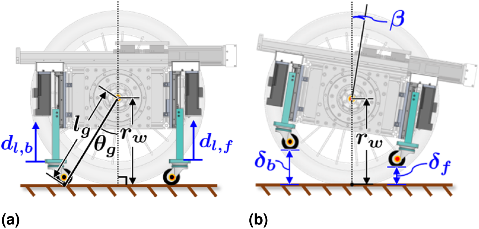
Leg-ground configurations between parking and two-wheel modes. (a) Parking mode and (b) two-wheel mode.
Parking mode to two-wheel mode
We determine the time instance at which the two-wheel mode begins, so that the passive state of the body enters the regime of active control. This is the instance when all the parking legs first meet the distance margin as they are being withdrawn simultaneously for transition, such that

Two-wheel mode to Parking mode
The moment for switching back to parking mode is determined by ensuring that the TWW transitions from active control to a passive state. This occurs when all the parking legs meets the distance margin while moving downward to the ground, defined as

Two-wheel driving
Driving control
The driving control strategy in the two-wheel mode aims for the rider to consistently maintain a stable posture while tracking a desired velocity generated by the joystick command. During the two-wheel mode, the CoG of the TWW should shift toward accelerating or decelerating direction.
Various driving postures can be configured by combining the TWW’s joint motions. That is, the CoG can be controlled either by tilting the wheelchair body and/or by positioning the seat slider. Among these options, we can adopt specific ones for the acceleration and deceleration phases, as illustrated in Figure 5. On the acceleration phase, the seat slider is made to move forward while keeping the pitch angle zero. But, during the deceleration phase, the seat slider is made to move backward while the seat is slightly set to tilt backward, because it can reduce the discomfort due to inertial lurch experienced by the rider. With the chosen strategy, a suitable trajectory planning method, which we call the dynamic inversion, is applied, taking into account the dynamic constraint of the system.

Desired postures during acceleration and deceleration phases. (a) Driving posture and (b) velocity profile.
For the purpose of easier handling of dynamics, the TWW system depicted in Figure 6(a) is simplified as an equivalent virtual 4-DoF serial manipulator, shown in Figure 6(b), exhibiting the same velocity kinematics. The equations of motion for the system can be expressed as (refer to Kim et al.
24
)

Schematic and equivalent model of the two-wheeled robotic wheelchair (TWW). (a) Schematic and (b) equivalent model.
To formulate trajectory planning problem, the output 

Trajectory planning by dynamic inversion of the TWW is to find 

To do this, we employ and adapt the asymptotic expansion technique
24
that treats the TWW system as a singularly perturbed system. Define the solution variables as

Kinematic and dynamic parameters of the two-wheeled robotic wheelchair (TWW).

Note :
To obtain the zeroth order sub solution, we first set up a system of equations as


Being that 
To enable tracking, a simple PD controller is chosen as
In summary, the zeroth-order terms
Unlike the most of previous studies where the motion control of two-wheeled systems heavily depended on complicated control methodologies such as Katariya, 13 Hu and Tsai, 14 Kim and Kwon, 15 Chiu et al., 16 Cui et al., 17 Yang et al., 18 our TWW system can achieve an outstanding tracking performance just by a simple PD controller due to using a desired trajectory based on the dynamic inversion method.
Joystick command processing
The joystick input that serves as the real-time reference velocity,
In the scaling, the joystick’s push-pull movement is to be adjusted to the longitudinal velocity, and the lateral movement is to be the yaw rate. Since the joystick’s motion range is circular, the adjusted velocity space for the TWW turns out to be an ellipse. This ellipse must entirely be contained in the diamond-shaped permissible velocity space defined by the speed limits of wheel motors, as shown in Figure 7. The scaling process is represented as

Joystick command and feasible space of velocity input.
Once the signal scaling is finished, then it should be filtered by using carefully designed low pass filters, not only to suppress the noise and high-frequency contents but also to satisfy the differentiability condition of the reference trajectory. With an abuse of notation,
Among many possibilities, we propose the followings, as the proper candidates of 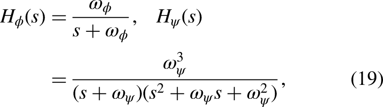


Safety management
The TWW operates normally when the system believes its safety, but, when the risk levels are high enough for the system to go into dangerous situations, the wheel and seat slider actuators are halted by the braking system and then the parking legs are lowered to support the system. To make decisions about the state of safety, a generic form of risk level is defined as
We select monitoring values that can affect the safety of the TWW, which may include the velocity and input torque of the two wheels and seat slider, the pitch angle of the TWW body, and the dynamic constraint of the TWW as introduced in the next section.
Experimental validation
To verify the performance and functionality of the developed TWW system shown in Figure 1, we carried out experimental tasks, including (i) mode switching task, (ii) prescribe longitudinal path tracking with an emphasis on verifying the transient characteristics, and (iii) indoor-outdoor arbitrary maneuver task. All experimental results are publicly accessible online at YouTube page. https://www.youtube.com/watch?v=iIIGzN0OJA8.
Mode switching task
Experimentation with the mode switching task was conducted on a flat terrain. The mode switching task was performed under different loads of {0, 10, 18, 26, 36, and 71.8(human)}[kg], and each case was tested 15 times to verify the robustness of the results. Transition from parking mode to two-wheel mode required 5.5[s] and the one from two-wheel mode back to parking mode required 6[s]. During the mode transitions, the quality of wheelchair’s movement were evaluated in terms of the perturbed distance for balance recovery and the amplitude of pitch angle.
Figure 8 shows the experimental results of the mode switching task with different loads, demonstrating that the TWW maintains the stable posture and balances well throughout all the cases of transitions from parking to two-wheel mode or vice versa. As shown in Figure 8, once the mode switch from parking to two-wheel mode was initiated at

Experimental results of mode switching. (a) Switching from parking mode to two-wheel mode, (b) switching from two-wheel mode to parking modes and (c) state.
For all the different load conditions, the mode switching task was completed successfully with no failure cases.
Longitudinal path tracking
Here, a set of longitudinal path tracking tasks was conducted to compare the characteristics of responses (i) with and without seat slider actuation and (ii) dynamic inversion and non-dynamic inversion, on flat and inclined grounds. The desired joint trajectory 
In the trajectory for the tracking task on the flat ground,
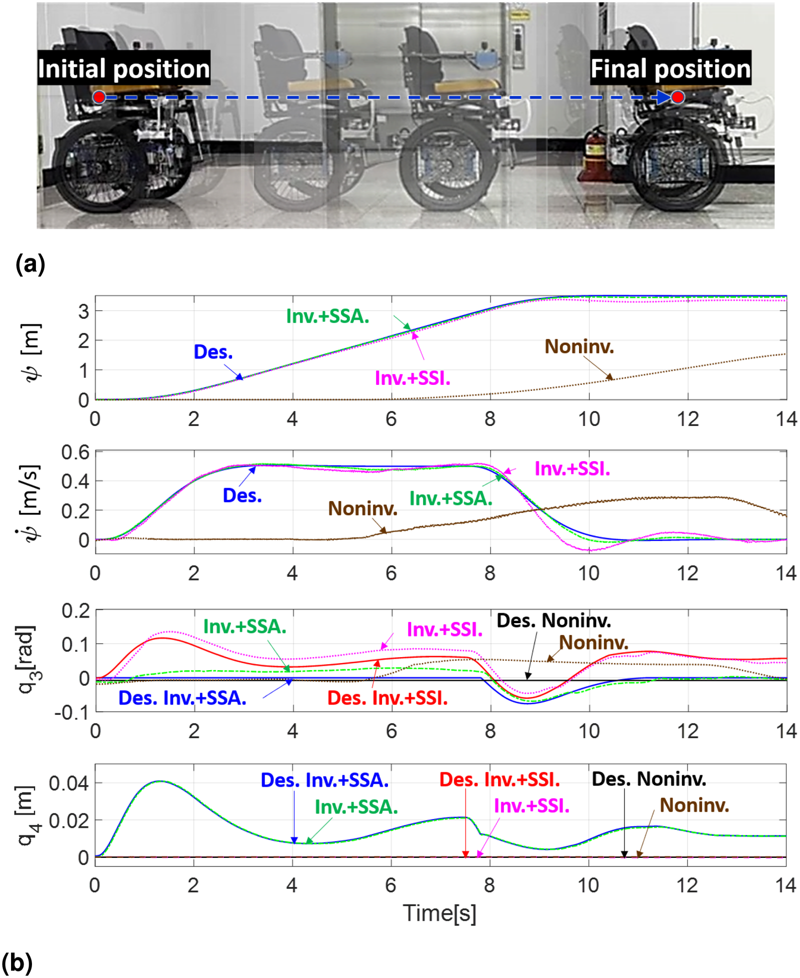
Experimental results for longitudinal tracking task on flat ground. (a) Longitudinal path and (b) Results. Des.: desired; Inv.: dynamic inversion; SSA: seat slider active; SSI: seat slider inactive; Noninv.: non-dynamic inversion
For the tracking task on the inclined ground,
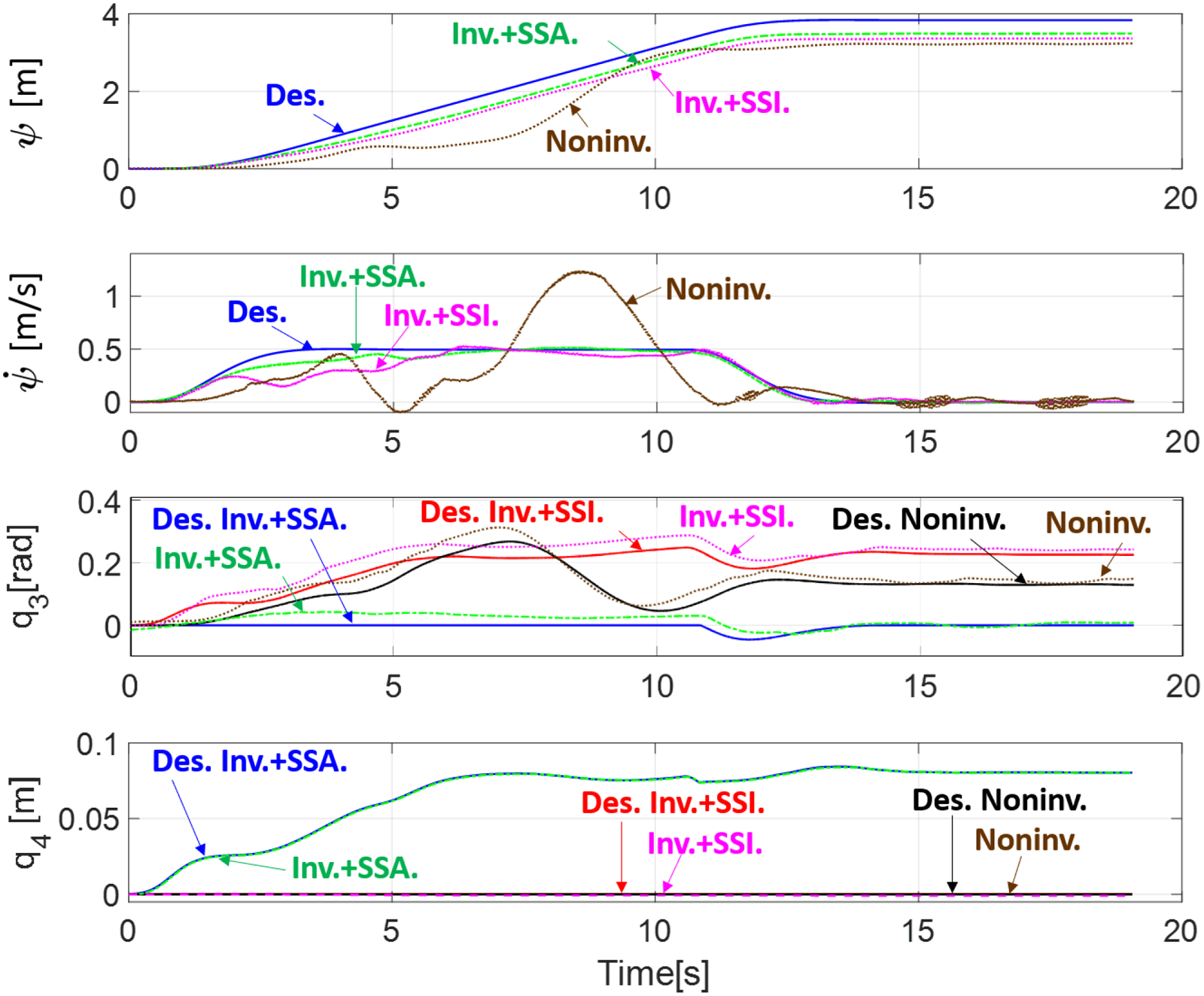
Experimental results for longitudinal tracking task on inclined ground. Des.: desired; Inv.: dynamic inversion; SSA: seat slider active; SSI: seat slider inactive; Noninv.: non-dynamic inversion.
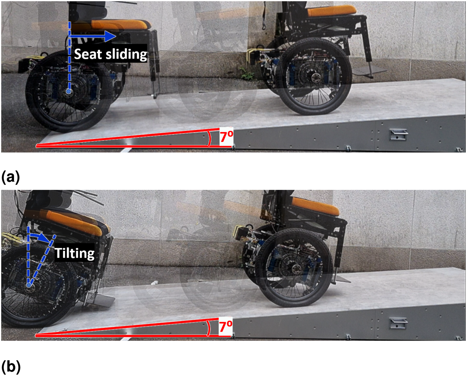
Posture difference between with and without seat slider actuation. (a) With seat slider actuation and (b) Without seat slider actuation.
Arbitrary indoor-outdoor navigation
The indoor-outdoor arbitrary navigation task driven by a human rider was conducted in and around a building as shown in Figure 12, to verify the overall functionality and general safety of the system. The task scenario was designed to replicate common challenges encountered during both indoor and outdoor navigation. This challenging task demonstrates the capability that the TWW is used as a daily personal mobility for the elderly and individuals, which demands precise posture control and enhanced stability. The navigation path of the task, roughly 95[m] long, included four typical zones: (A) a door threshold of 3[cm] height and

Experimental environment for arbitrary navigation task.
Figure 13 shows that the arbitrary navigation task was successfully completed without any safety issues, as the risk level was within the safe limit during the entire task. Even in passing through hazardous zones, the TWW successfully managed the balancing and posture stability only with mild reaction. Specifically, when the TWW was crossing zone (A) and zone (C), a rather large variation in

Experimental result for arbitrary navigation task.
In terms of the overall tracking performance, it was generally good during the entire course of tracking task unless severe disturbances were not present. In addition, the seat back posture
Conclusion
This paper presented a TWW equipped with a seat slider, enhancing controllability and riding comfort in both indoor and outdoor settings. The traditional challenges associated with two-wheeled mobility systems such as the balancing and posture stabilization have been easily manageable by the developed system. In addition to the wheelchair’s mechanical enhancement, a dynamic inversion based real-time trajectory planner that takes into consideration the mobility of seat slider has been proposed. This not only helps control the posture of the wheelchair but also improves its ability when navigating through obstacles such as door thresholds, narrow passageways, and inclines. The experimental results have shown that the developed two-wheeled wheelchair has an improvement in handling its posture and stability without any safety issues. We believe this system can be an effective personal mobility option for the elderly and individuals with lower limb disabilities in facilitating greater independence in their daily activities. The proposed system can offer a promising potential as an autonomous transport device. By integrating additional sensors for environmental perception, the wheelchair could evolve into a highly capable autonomous mobility solution.
While this study demonstrates the advantages of the TWW, certain limitations should be considered for practical applications. The joystick-based control system may be unfamiliar to some users, requiring a level of understanding and adaptation for effective operation. Ensuring user-friend and intuitive design would be critical for broader adoption.
Supplemental Material
Footnotes
Declaration of conflicting interests
The authors declared no potential conflicts of interest with respect to the research, authorship, and/or publication of this article.
Funding
The authors received the following financial support for the research, authorship, and/or publication of this article: This work was supported partly by the National Research Foundation of Korea(NRF) grant funded by the Korea government(MSIT) (No. NRF-2021R1A2C1095085), partly by a major project of the Korea Institute of Machinery and Materials (Project ID: NK250F), partly by a major project of the Korea Institute of Machinery and Materials (Project ID: NK254F), and partly by the Korea University grant.
Data availability statement
Data sharing not applicable to this article as no datasets were generated or analyzed during the current study.
Supplemental Material
Supplemental material for this article is available online.
References
Supplementary Material
Please find the following supplemental material available below.
For Open Access articles published under a Creative Commons License, all supplemental material carries the same license as the article it is associated with.
For non-Open Access articles published, all supplemental material carries a non-exclusive license, and permission requests for re-use of supplemental material or any part of supplemental material shall be sent directly to the copyright owner as specified in the copyright notice associated with the article.