
Abstract
Autonomous valet parking is an L4-level self-driving technology that solves the “last-mile freedom” of automobile users. Aiming at the motion planning problem involved in the decision-making layer of autonomous valet parking, this article proposes a trajectory planning method that obtains global time optimization by solving the optimization problem. The method is based on the path points obtained by the improved hybrid A-star algorithm as the reference waypoints. The global trajectory planning problem is segmented. In each section, the physical system constraints of the vehicle, the boundary condition constraints, and obstacle avoidance constraints in the parking process are comprehensively considered, and the parking trajectory planning task is described as an optimal control problem. The optimal problem is transformed into a nonlinear programming problem by the numerical optimization method. Finally, the global optimal trajectory is obtained on the basis of ensuring the continuity of state variables and control variables. Simulation experiments verify the effectiveness of the algorithm for horizontal and vertical parking. The real vehicle test shows that the vehicle can be safely, quickly, and accurately parked in the parking space.
Introduction
With the rapid development of automotive intelligence, networking technology, and the application of advanced sensors, the vehicle parking system has evolved from assisted parking in the early stage and fully automatic parking in the middle stage to L4 autonomous valet parking (AVP). AVP is an autonomous driving in a specific area scenario, and the driver can send instructions through the mobile terminal device to complete the process of parking or picking up the car. AVP can greatly save parking time, improve parking efficiency, solve the parking safety problem caused by lack of driving experience, and realize the “last mile” of unmanned driving. Therefore, AVP is an indispensable part of autonomous driving technology for engineering application scenarios.
Motion planning is one of the key technologies to realize AVP. The main task of motion planning is to generate a geometric path or trajectory connecting the starting point and destination of the vehicle, which is divided into path planning and trajectory planning. The latter is solved in the state space based on path planning, and the results include time-related parameter information of the vehicle traveling along the geometric path. Therefore, the chassis actuator can directly track this trajectory, so it can be considered that the results of trajectory planning are more comprehensive than those of path planning.
Many scholars and research institutions at home and abroad have carried out a lot of research on the motion planning problem of autonomous vehicles. The research results can be roughly divided into five categories. Geometric line construction methods, such as Dubins curve, 1 Reeds-Shepp curve, 2 the curve composed of multiple arcs and straight lines,3,4 polynomial fitting curve, 5 and cyclotron curve. 6 The planning results using geometric line construction methods are mostly paths, and further smoothing is required. Graph search methods need to be solved by graph theory on the basis of binary processing of the map. For example, Dijkstra algorithm, 7 improved A * algorithm, 8 Jump Point Search method, 9 and Hybrid A * algorithm 10 proposed in 2010 (DARPA) city challenge. Random sampling methods mainly include the probabilistic road map (PRM) method and the rapid-exploration random tree method. The PRM algorithm cannot deal with complex constraints such as differential equations existing in vehicle motion, resulting in poor feasibility of PRM generation path. 11 The rapid-exploration random tree algorithm is suitable for solving motion planning problems with differential equation constraints. 12 The solution quality of this method is unstable and cannot directly deal with motion planning tasks with complex constraints. With the development of artificial intelligence technology, intelligent algorithms are widely used in vehicle motion planning, such as genetic algorithm, 13 particle swarm optimization algorithm, 14 Monte Carlo 15 method, and motion planning based on you only look once deep learning model.16,17 The computational cost of intelligent optimization algorithms is high, and most of them are used in offline optimization. The fifth category of methods is numerical optimization methods. The general idea of the numerical optimization method is to transform the vehicle motion planning problem into a nonlinear optimal control problem with an objective function. By using numerical optimization algorithms to solve the optimization control problem and obtain planning results. Martinsen et al. 18 combined the graph search method with the convex optimization method to obtain the vehicle trajectory. Qin et al. 19 divided vehicle trajectory planning into two stages: linear programming and nonlinear programming (NLP) to obtain accurate solutions. Liu et al. 20 established the dynamic optimization problem of vertical parking and used the two-stage Gaussian discrete method to solve the partial differential equation to obtain the final trajectory. The biggest advantage of this method is that the planning result is a trajectory rather than a path. Due to the complexity of the algorithm's description of constraint conditions, it is more suitable for local planning rather than global planning.
In the AVP process, the vehicle travels far away, and the significant feature of global trajectory planning is that the scene is large, so that there are many nontarget obstacle parking spaces to be considered. If numerical optimization is directly used to solve the trajectory, the complex constraint conditions lead to an extremely low convergence success rate. If the geometric line method, or the graph search method, or the probability graph method is used, although the planning can be solved in a short time, the planning result is the path. The geometric path information needs to be further converted into time parameters such as vehicle speed and steering wheel angle for the trajectory tracking of the chassis actuator. Therefore, it is of great significance for the development of AVP system to directly solve the optimal trajectory of vehicle motion in AVP process.
In this article, a method to obtain the global time optimal trajectory of AVP by directly solving the optimal control problem was proposed. First, an improved hybrid A-star algorithm was adopted to obtain the global path of the AVP process. The improved hybrid A-star algorithm could ensure that the global path solving process is fast and accurate. Second, the AVP process was segmented according to the global path. In each segment, the shortest parking time was taken as the optimization objective, and the numerical optimization method was used to solve the optimal trajectory. Of course, the continuity of vehicle state variables and control variables between different segments should be guaranteed. The global path can be used not only as a basis for segmentation but also as an initial reference for numerical optimization to address the defect that numerical optimization methods are sensitive to initial values. Finally, the segmented trajectories are combined into a global optimal trajectory.
The advantage of the segmentation processing is that it reduces the constraint cost that needs to be considered when solving the segmented trajectory. At the same time, the global path based on the improved hybrid A-star solution is used as the initial reference for the numerical optimization solution, which greatly improves the convergence rate of the numerical optimization process. It overcomes the defect that the numerical optimization method is usually applied to local planning. Through the method proposed in this article, the numerical optimization can be applied to the one-time solution of the global optimal trajectory of the AVP process.
AVP scene and global trajectory planning process description
In this article, a medium-sized parking lot is chosen as the scene for verifying the algorithm, with vertical parking spaces evenly distributed around the edges and in the middle of the parking lot, as shown in Figure 1(a). The entrance of the parking lot is chosen as the starting position when the driver opens the AVP system, assuming that the parking lot has been transformed by intelligent facilities and the vehicles can communicate with the intelligent parking system (V2I), and that the free parking spaces can be detected by the parking space sensing system and assigned to the vehicles entering the parking lot. The process of global trajectory planning for AVP can be divided into two phases after specifying the target parking space. In order to identify the two phases more intuitively, the three-dimensional view of the parking lot is converted to top view, as shown in Figure 1(b). The first stage is for the vehicle to automatically move from the entrance of the parking lot to the optimal starting point for vertical parking, namely the A–B section, which is also called the navigation planning stage, and the motion planning in this stage includes the two steps of the navigation path planning and the navigation trajectory planning as mentioned above, and the second stage is for the vehicle to park in the parking space from the optimal starting point for vertical parking, namely the B–C section, which is also called the vertical parking planning stage, and the motion planning in this stage includes the parking trajectory planning as mentioned above.

Medium-sized parking lot. (a) Aerial view of parking lot and (b) diagram of valet parking process.
After receiving the target parking space number sent by the intelligent parking system of the parking lot, the AVP system first needs to clarify the position of the A–B and B–C segment correlation points, that is, the optimal starting point of the vertical parking stage. After determining the position of the associated points, an improved hybrid A-star algorithm, a graph search algorithm with kinematic constraints, is applied in the navigation planning stage to generate the globally optimal path from the entrance of the parking lot to the endpoint of the navigation stage. The global path is segmented and used as a reference route point. The local optimal trajectory planning problem is transformed into a nonlinear optimal control problem in each segment, and it is solved iteratively by the numerical optimization method. In the vertical parking planning stage, the time optimal trajectory is obtained directly by solving the optimal control problem. Throughout the global trajectory planning of AVP, the termination time of each trajectory planning in the A–B segment and the starting time of the next planning, as well as the termination time of the A–B segment and the starting time of the B-C segment, must meet the following endpoint constraints: the vehicle's X and Y direction coordinates, body heading angle, vehicle speed, and steering wheel rotation angle must be consistent, so as to ensure that the optimal trajectories of the two stages are seamlessly connected to form the final global time optimal trajectory.
Kinematics model
The vehicle kinematics model is the basis of the search tree expansion in the hybrid A-star algorithm and the trajectory calculation in the numerical optimization algorithm. Therefore, a correct vehicle kinematic model is a powerful guarantee for the accuracy of global path planning. Considering that the search tree in the hybrid A-star algorithm can be expanded into two scenarios: circular arc and straight line, the corresponding vehicle kinematic model can also be divided into two scenarios. As shown in Figure 2(a), when expanding the circular arc based on the center point of the rear axle


Vehicle kinematic model. (a) Arc expansion and (b) straight line expansion.
Based on the above kinematic model, the optimal position and heading angle for the next search step can be planned using the hybrid A-star algorithm. This model only contains the geometric relationships between position, heading angle, step size, and steering wheel and is not suitable for trajectory planning process to solve the optimal objective function. Therefore, the above kinematic model will be detailed. Vehicle AVP process is low-speed driving, the tires are always pure rolling state, and there is no side slip, ignoring the tire lateral force and other dynamics. Only the vehicle's kinematic characteristics are considered. According to the Ackermann steering principle, the detailed kinematic model of the vehicle can be refined into the following kinematic differential equations:

Navigation phase path planning based on improved hybrid A-star algorithm
The hybrid A-star algorithm is an effective fusion of search tree method and A-star algorithm. It retains the classic heuristic idea of A-star and considers the limitations of the vehicle kinematic model when expanding the search tree nodes, that is, satisfying the maximum curvature constraint of the vehicle. Expanding two-dimensional search to three-dimensional space can plan continuous vehicle position and attitude changes in a discrete grid.
The traditional hybrid A-star algorithm adopts a fixed-step node expansion method in each expansion direction, and its search effect is greatly affected by the number of expansion directions and the search step size. When the expansion direction is more or the search step is smaller, the search time is longer and the efficiency is lower. When the expansion direction is less or the search step is larger, the path is rough, the smoothness is not enough, and the possibility of collision with obstacles increases. In order to better balance search efficiency and path quality, this article proposes a new subnode expansion method while optimizing the motion cost function and collision detection method. It adopts a variable step size node expansion method, which can ensure the smoothness and security of the searched path and greatly improves the efficiency of path search. Meanwhile, the optimized motion cost function and collision detection method prevent nodes from expanding along unnecessary regions or directions, further improving the real time and security of path search.
Grid occupation map and resolution description
The node extension of the hybrid A-star algorithm is based on a grid map, using 0 and 1 to distinguish whether the smallest grid unit in the map is occupied by obstacles, where 1 indicates the presence of obstacles in the pointed grid unit, and 0 indicates that the grid unit is idle. Therefore, the higher the resolution of the map, the smaller the basic grid units, and the more accurately the obstacle occupancy information in the scene can be expressed. The map resolution can be determined using the following equations:


Vehicle motion diagram.
Extension method for variable step length child nodes
The first step in expanding child nodes is to determine the number

When expanding forward, the step sizes in each direction are not equal, as shown in Figure 4. The specific step size can be calculated using the following equations:

Number of node expansion directions
In the equation,
Obstacle collision detection method
The actual top view projection shape of the vehicle is close to a rectangle. In the navigation planning stage, the environment is relatively open, and its contour does not need to be accurately described. The multicircle expansion can be used to describe the vehicle contour, as shown in Figure 5. Compared with the extremely accurate description, the computational complexity is reduced, and it can be well used for the mathematical expression of collision detection.

Multicircle expansion description of vehicle contours.
Among them,

Combining the above parameter relationships and the current position

The corresponding collision processing is performed on the grid units occupied by obstacles in the map to better perform collision detection. The condition that there is no collision between the vehicle and the obstacle is that there is no overlap between the vehicle contour circle and the obstacle contour circle, and the constraint condition can be expressed by equation (11). Collision detection is performed on each vehicle pose obtained by the expansion. If the vehicle collides with an obstacle at that node pose, stop expanding the node toward the outer layer in that direction to ensure that the path between each child node and the parent node is collision free.

Improved motion cost function
The overall objective function of the hybrid A-star includes two parts: the motion cost function g and the heuristic function h. The motion cost function

Among them,

In the equation,

Trajectory planning based on numerical optimization methods by solving optimal control problems
Through the improved hybrid A-star algorithm, the global optimal path in the navigation stage can be obtained, and this path satisfies the vehicle kinematic constraints. However, the executing mechanism of the vehicle chassis cannot directly track this path, and the path needs to be further optimized to obtain the corresponding trajectory, such as torque or throttle opening, vehicle speed or acceleration, front wheel angle or front wheel angular velocity, which can directly control the vehicle's parameter information. The specific method of global trajectory planning proposed in this article is to use the above path as a reference waypoint, segment the reference waypoint, and describe the trajectory planning problem as a time-optimal nonlinear control problem within each segment. The optimal trajectory is obtained by solving the optimal control problem using the numerical optimization method. The advantage of segmented solution lies in the ability to divide the previously complex global parking optimal trajectory into multiple stages of parking trajectory solving. The obstacle collision avoidance constraints and endpoint constraints during each stage of solving are simplified, thereby improving the success rate of trajectory solving and the real-time performance of the algorithm.
Description of the optimal control problem for AVP trajectory planning
The vehicle motion trajectory planning problem can be described as an optimal control problem through an accurate mathematical model. The optimal control problem generally includes the dynamic differential equation, constraint conditions, and performance index function of the controlled system. The constraint conditions include equality constraints and inequality constraints. The optimal control parameters are obtained by solving the performance index function when the controlled system reaches the minimum value under the constraint. Without loss of generality, the nonlinear optimal control Bolza problem for AVP trajectory planning can be described as:


Inequality constraints
When solving the trajectory problem of AVP, inequality constraints usually include vehicle collision avoidance constraints, vehicle physical constraints, and boundary condition constraints. Different from the rough description of the vehicle itself in the global path planning process, the description of the vehicle in the local trajectory planning process needs to be more precise to absolutely avoid collisions. Figure 6 shows the vehicle collision avoidance strategy during the AVP process. The actual overhead projection shape of the vehicle is close to a rectangle. Here, an enlarged rectangle is used to describe the vehicle contour, as shown in the Figrue 6.

As shown in the Figure 6, in order to ensure that the vehicle is always driving on the road, it does not collide with the vehicle in the parking space. In the A–B stage, each parking space is regarded as an obstacle alone, and in the B-C stage, the remaining parking spaces other than the target parking space are regarded as obstacles. In order to reduce the number of obsacles to be considered in trajectory planning, simplify the collision avoidance constraints, and improve the efficiency of the algorithm, only the parking spaces within the circular range in the graph are considered as obstacle parking spaces in each trajectory planning process. The two-stage collision avoidance method is consistent, that is, if the car does not break into the obstacle parking space and collide with other vehicles, the geometrical significance of this constraint in the two-dimensional plane is: then at any moment, no point on the obstacle parking space falls within the contour of the enlarged self-vehicle rectangle. Taking the two obstacle parking spaces

In the equations,

When the straight line

Similarly, the collision points of other considered obstacles need to meet the above conditions, that is,

In the equation,

Equality constraints
In real-time control, the shorter trajectory in the B–C stage can be directly generated, while the trajectory generation process in the A–B stage is segmented to ensure that in the event of dynamic obstacles, the generated trajectory can avoid collisions, and the shorter trajectory length is conducive to real-time calculation. The path generated by the improved hybrid A-star algorithm containing three dimensions

Transformation of NLP problems
Time domain transform
Within the sampling segments of each waypoint mentioned above, map the time domain

The Bolza problem can be transformed into a standard problem using equation (24), which is described as follows:


In the equation, x and u are the state variables and control variables, respectively.
Discretization of variables
The optimal control problem is discretized into variables at a series of Legendre Gauss points using Lagrange interpolation and Gaussian quadrature equation. The state variables are discretized into


Conversion of constraints and performance indicator functions
Transforming the dynamic differential equation into an algebraic equation, the approximate derivative of the state variable can be obtained by differentiating equation (27) as follows:

The differential matrix

In the equation,

Similarly, the discretized inequality constraints and equality constraints are represented as follows:

Using the Gaussian quadrature equation to approximate the performance indicator function into:

In the equation,

In summary, by discretizing the allocation points, the Bolza optimal control problem is transformed into a standard NLP problem, which provides a basis for approximate solution of subsequent optimal control problems.
Determination of endpoints for stages A–B and B–C
For parking lots that have undergone intelligent infrastructure transformation, when vehicles enter the parking lot, the intelligent parking system has already allocated idle parking spaces. Each idle parking space has a marked position


Parking space obstacle avoidance constraint diagram.

Determination of the endpoints of stages A–B and B–C.
As can be seen from the figure, for each target parking space, it is assumed that it can be parked from two directions, with the left and right sides of the parking space corresponding to the endpoints
The length of
For target parking spaces in different directions, the coordinate values of connection point


By using equations (41) and (42), the two target endpoints for stage A–B can be determined for different target parking spaces. The premise for these two points to become feasible A–B stage target endpoints is to meet the following two requirements: (1) These two points are within the range of the parking lot map and (2) The vehicle does not come into contact with any obstacles at these two points.
Framework of time-optimal global trajectory planning algorithm
The process of the time-optimal global trajectory planning algorithm for AVP is shown in Figure 8. On the premise of clarifying the target parking space, an improved hybrid A-star algorithm is first used to quickly obtain a collision-free A–B phase reference waypoint. The numerical optimization method is used to solve the optimal trajectories of the A–B stage and the B–C stage, and the above reference route points are used as the initialization conditions for the trajectory solving process of the A–B stage to improve the convergence success rate and efficiency of the numerical optimization method in solving long-distance and multiobstacle trajectories; finally, a global optimal trajectory that can be used for direct tracking control of the vehicle chassis is obtained.
Time optimal global trajectory planning algorithm framework.
Simulation and verification
A–B segment path planning based on improved hybrid A-star
Based on the MATLAB platform, a large-scale parking lot map is built to simulate the global trajectory planning of AVP. The improved hybrid A-star algorithm is compared with the traditional hybrid A-star algorithm to verify the superiority of the improved algorithm. As shown in Figure 9, the parking lot contains 495 vertical parking spaces distributed around and in the center of the parking lot. The azimuth of the parking spaces included four situations: [

Map of medium and large parking lot.
Parameters involved in planning the simulation.
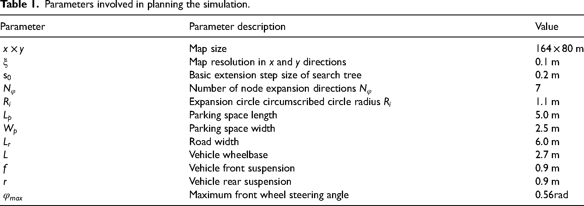
Figure 10 shows the parking lot map after binarization of 0 and 1 on the grid map. The nonobstacle area is 0 and marked in white, while the obstacle area is 1 and marked in gray. Figure 11 shows the feasible driving range of the vehicle in the parking lot after the expansion of the vehicle on the basis of the binary map. The red area represents the area where the vehicle may enter the collision area, and the white area represents the feasible driving area. Although the feasible driving area is reduced, the obtained path can provide more constrained waypoints for trajectory planning.

Parking lot map after 0 and 1 binarization on raster map.

The allowable driving range in the parking lot obtained by inflating the vehicle.
After determining the obstacle and drivable areas of the grid map, assuming that the vehicle is located at the entrance of the parking lot, the center point of the rear axle of the vehicle is selected as the starting node, and the starting node coordinates are (82,2,

(a) Traditional A-star algorithms, (b) improving the cost function, (c) node expansion using variable step size, and (d) improvement of the cost function and node expansion approach.

(a) Traditional A-star algorithms, (b) improving the cost function in the objective function, (c) node expansion using variable step size, and (d) improvement of the cost function and node expansion approach.
It can be seen that for different target parking spaces, both the traditional hybrid A-star and the improved hybrid A-star algorithm can solve the path of the A–B stage in the drivable area after the expansion of the obstacle contour, which is a purple curve. However, there are significant differences in the optimization results. The dark blue and light blue lines in the figure are the extension trees of the algorithm, with dark blue indicating forward motion and light blue indicating reverse motion. In condition 1, only one of the two A–B stage destinations solved by equations (39) and (40) meets the A–B stage target endpoint requirements. The optimization results of the traditional A-star algorithm are shown in the figure. There are many turning situations on the path, and the average curvature of the path is relatively large, which does not meet the expectation of the vehicle's AVP system for optimal time because any turning may affect the vehicle's lateral stability and reduce parking safety. At the same time, during the path search process, there are more nodes to be extended, which can be directly determined by the dense extension trees in the graph, resulting in lower search efficiency. The cost function in the objective function has been improved by adding a cost term for path curvature, but the optimization results obtained without improving the search tree extension method are shown in the figure. As shown in Figure 12(a) and (b), the number of path turns obtained in Figure 12(b) is significantly reduced based on the motion cost function improvement, and the path mean curvature is reduced. Simply improving the motion cost function in the hybrid A-star algorithm achieves the goal of reducing the mean curvature, but it has to expand more nodes than the traditional A-star algorithm. Simply improving the motion cost function in the hybrid A-star algorithm achieves the goal of reducing the mean curvature, but it has to expand more nodes than the traditional A-star algorithm. This is also verified in Figure 13(b). The light blue area in the figure is the expansion tree of the node expansion process, which is significantly increased compared with Figure 13(a). Figure 12(c) shows the path search results of the hybrid A-star algorithm after only adopting the variable step node expansion mode. It can be seen that the expanded nodes are drastically reduced, the search efficiency is greatly improved, and the real-time performance of the algorithm is enhanced. However, many turning conditions in the path may result in trajectory planning results that are not globally optimal in time. Figure 12(d) and Figure 13(d) show the path search results after the above two improvements are adopted simultaneously in the hybrid A-star algorithm. It can be seen that the paths obtained not only have a low mean curvature but also a significant reduction in the number of expanded nodes, and the smaller number of expanded nodes effectively improves search efficiency. Table 2 shows the number of nodes expanded and finally saved when using the traditional hybrid A star and the improved hybrid A star to solve the final path.
As can be seen from the table, the hybrid A-star algorithm for both working conditions has significantly reduced the number of nodes expanded in obtaining the optimal path after improving the node expansion method, and the retrieval efficiency is significantly improved. However, compared to the traditional hybrid A-star algorithm, the node expansion in solving the optimal path is increased by only improving the motion cost function, which is mainly due to the penalization of turning for the optimal path, which leads to the algorithm needing to expand more nodes in order to retrieve the optimal path with the least number of turning conditions.
Obtaining the time-optimal trajectory by solving the optimal control problem
After obtaining the optimal path, the numerical optimization method is used for global trajectory planning of AVP, involving vehicle parameters and constraint parameters as shown in Table 3. In the A–B stage, the reference waypoints obtained based on the improved hybrid A-star algorithm under two operating conditions are shown in Figure 14. Among them, operating condition 1 obtained 36 reference waypoints, and operating condition 2 obtained 32 reference waypoints. When using the hybrid A-star algorithm for path planning, vehicle kinematic constraints are considered, so each waypoint contains three dimensions of information, that is, lateral displacement, longitudinal displacement, and heading angle. Segmenting the reference waypoints at intervals of every five waypoints, with the reference waypoints at the connections between the front and back sections remaining consistent to ensure the continuity of the state variables. In each section of the flight, the local trajectory planning problem within the segment is transformed into an optimal control problem, which is then solved through numerical optimization methods. By setting each waypoint as the initial value for numerical optimization, the convergence rate can be greatly improved.

Reference waypoints obtained based on an improved hybrid A-star algorithm.
Number of nodes extended and final waypoints.

Vehicle parameters and physical constraints.

The advantage of segmented solution is that when establishing obstacle avoidance constraints for vehicles within each segment, only the no target parking spaces within a certain range of the current reference waypoint are considered as independent obstacles, which greatly reduces the number of obstacles that need to be considered in global one-time trajectory planning. Due to the processing of segmented planning, the number of times obstacle parking spaces near the reference waypoint are considered in the segmented trajectory solving process varies. The number of times this obstacle was considered during the segmented iterative solution process is indicated by the different color depths in Figure 15. It can be seen that obstacle parking spaces near areas with dense waypoints are considered more frequently, resulting in darker colors. As the distance from the vehicle increases, further obstacle parking spaces are considered less frequently, and the color gradually becomes lighter. White parking spaces further away represent those that were not considered as obstacle parking spaces in the trajectory planning process. This is because the more waypoints there are, the more iterations the solution takes, and the closer the obstacle parking space is to the waypoint, the more times it is considered as an obstacle. The green box in the figure represents the vehicle trajectory in stages A–B, while the purple box represents the vehicle trajectory in stages B–C. The red curve represents the trajectory of the vehicle at the center of the latter during the entire autonomous parking phase. As can be seen from the state parameters of the vehicle in Figure 16, the planning results of the vehicle state parameters and control parameters are strictly limited to the constraints in Table 3, and the sign of the vehicle speed changes once for the two parking conditions, which verifies that the vehicle undergoes a back and forth maneuver during the vertical parking process, which is in line with the actual parking situation, and it is shown in Figure 16(a) that the total time used is 48 s, and in Figure 16(b) that the total time used is 41 s. This is because the second parking space is closer to the entrance. This is because the second parking space is closer to the entrance and takes a shorter time.

Schematic diagram of the autonomous parking stage process.

Simulation results of states and control variables for two different vehicle positions.
We added the types of parallel parking spaces that are common in life to further verify the effectiveness of the algorithm. Combined with the actual situation, the four weeks of the above parking lot are changed into parallel parking spaces, as the situation of parallel and perpendicular parking modes in the A–B navigation planning stage of the whole AVP process is exactly the same because the planning process of the navigation points is not given here, and the results of the multisegment global time-optimal trajectory planning are given directly, as shown in Figure 15(c) and (d). In the two figures, it can be seen that the optimal navigation reference points are solved based on the improved hybrid A* algorithm for segments A–B. The numerical optimization method quickly obtains the optimal trajectory based on the navigation points as the initial values. No vehicles collide with other parking spaces in the A–B stage. And in stage B-C, the planning results can show the powerful solution advantage of the proposed numerical optimization solution method. In the two parallel parking processes, under the premise of no collision with adjacent front and rear parking spaces, the vehicles need to be adjusted through several front and rear maneuvers before they can finally be parked into the parking spaces. This is mainly due to the simulation set up parallel parking for the length of 5 m; the space is shorter, and the orientation of the vehicle needs to be adjusted many times in the parking process. At the same time, it also serves to verify the powerful optimization capability of the proposed numerical optimization solution.
As can be seen from the vehicle parameter diagrams in Figure 16(c) and 16(d), the positive and negative repeated switching of speed and front wheel angle can verify that the vehicle needs to maneuver forward and backward several times during parallel parking to ensure that the vehicle can safely park in the parking space. This also leads to an increase in the cost of parking time when the parking space is too short compared to vertical parking. The parking completion time of the two parallel parking conditions is about 1 min. In the whole process of AVP, each state and control parameter of the vehicle strictly meets the constraint conditions, and its value is within the constraint range.
Real vehicle test
Choose a small, pure electric car to build a testing platform for the AVP system. As shown in the figure, the testing platform consists of three main parts. The first part is the environmental perception system, which consists of LiDAR, millimeter wave radar, binocular cameras, and a combination navigation system. The second part consists of computing units, including high-performance industrial control computers and embedded autonomous driving underlying software platforms. The underlying software platform uses the Baidu Applo platform. The third part is the wire-controlled chassis execution system, which consists of wire-driven, wire-controlled braking, wire-controlled steering system, and vehicle controller unit. The angle sensor of the electric power steering system provides the steering wheel angle signal, and the wheel speed sensor and the acceleration sensor provide the wheel speed pulse signal, the longitudinal acceleration signal, and the yaw rate signal, respectively. A 220 V power supply is provided to the industrial computer through the inverter. Figure 17 shows the communication architecture between the three parts. The environment awareness system communicates with 4G routers through Ethernet. As the communication gateway between the environment sensing system and the industrial computer, the 4G router collects the sensing information from each sensor and transmits it to the industrial computer, receiving the feedback information of the industrial computer in real time. The vehicle controller unit acts as a communication gateway between the wire-controlled chassis and the industrial computer, and communicates with the two through the CAN bus. The trajectory planning software based on hybrid A-star and pseudo-spectral method is embedded in Applo as application layer software in a Linux system environment. The calculation platform processes the above-mentioned sensor signals and calculates the parking target trajectory information and control variables, including the target angle, the target speed, and the target gear and sends the target control signal to each execution control system.

(a) Testbed for autonomous valet parking system and (b) communication architecture between the three main parts of the testbed. VCU = vehicle controller unit.
A small parking lot is selected for the calibration test of the integrated navigation module, LiDAR, and millimeter wave radar, and an autonomous driving map suitable for AVP is established. Figure 18 is the point cloud image obtained by the real vehicle scanning the parking lot environment during the LiDAR calibration process.

Point cloud view of the parking lot environment.
Considering the actual scene of the owner using the function of AVP, the parking starting point is set to the entrance outside the parking lot. It is assumed that the intelligent parking system has sent the target parking space to the vehicle end; that is, the vehicle has identified the target parking space coordinate point. The vehicle travels to the entrance of the parking lot and keeps the vehicle stationary, and then the automatic parking system takes over the vehicle. The parking system plans the parking trajectory of the A–B section and the B–C section according to the current position and the target parking space coordinates and sends it to the bottom actuator of the vehicle for execution. The actuator guides the vehicle according to the planning information. The real vehicle test process is shown in Figure 19.

Realistic vehicle testing process.
As can be seen from the figure, the parking system receives the parking instruction, the decision-making layer plans the parking trajectory and sends it to the steering, driving, braking, and other actuators, and at the same time guides the vehicle to complete the valet parking and no collision occurs in the process, completing the parking time is about 21 s, the parking process is smooth speed changes, no rapid acceleration, or deceleration occurs. The vehicle easily produces a large lateral deviation when turning, and when traveling on a straight road, due to the small target corner, the lateral deviation is smaller. In the process of completing vertical parking, although the steering wheel angle is larger, the lateral deviation generated by the vehicle is still smaller due to the lower speed. The real-vehicle test shows that the trajectory information obtained using the method in this paper can effectively guide the completion of autonomous parking.
Conclusions
The innovation point of this article is that an algorithm is proposed to quickly solve the global time optimal trajectory of AVP, which solves the problem of slow convergence rate or low success rate of one-time solution of AVP global trajectory through multistage numerical optimization. At the same time, the problem of continuity of state variable and control variable in the process of multi-stage solution is solved. To solve the numerical optimization problem of AVP being sensitive to the initial value, the improved hybrid A* algorithm provides a reliable initial reference point for the multistage trajectory solution and enhances the success rate and efficiency of the solution. The algorithm has specific application value in solving practical projects.
In this article, a global time-optimal trajectory planning method based on an improved hybrid A-star algorithm and NLP is proposed for the motion planning problem involved in the decision-making layer of AVP.
By segmenting the global trajectory planning problem and comprehensively considering the vehicle physical system constraints, parking boundary condition constraints and obstacle avoidance constraints, as well as taking the shortest vehicle parking completion time as the optimal objective function, we establish a nonlinear planning NLP problem based on the (Legendre Gauss) mating point and solve it, and ultimately obtain the globally optimal trajectory based on the guarantee of the continuity of the state variables and control variables.
Simulation results show that the improved hybrid A-star algorithm can effectively reduce the number of node extensions, improve the search efficiency, and reduce the path mean curvature. The global trajectory obtained by the segmented nonlinear planning method effectively avoids collisions and improves parking safety.
As an accurate local planning method, motion planning method based on numerical optimization usually requires high computational cost. Our group has been committed to reducing the computational cost in the numerical optimization process and improving the convergence rate. The group is trying to apply advanced algorithms such as neural networks and deep learning to parking trajectory planning to reduce the computational cost problem in dynamic and complex environments.
Footnotes
Declaration of conflicting interests
The authors declared no potential conflicts of interest with respect to the research, authorship, and/or publication of this article.
Funding
The authors disclosed receipt of the following financial support for the research, authorship, and/or publication of this article: This work was supported by the National Science Foundation of China (Grant No. 42405069), the University Natural Sciences Research Project of Anhui Province (Grant No. 2023AH052201 and 2023AH052184), 2023 Talent Research Fund Project of Hefei University (No.23RC01), 2023 Anhui Province Undergraduate Quality Engineering Construction Project (No.2023xjzlts046), and the technical development project of Hefei University (No.902/22050124149,No.902/22050124148 and No.902/22050124128).
Data availability statement
Data sharing not applicable to this article as no datasets were generated or analyzed during the current study.