
Abstract
Background
The combination of MR and robotic technology can improve surgical accuracy, shorten surgical time, and even improve the location of lesions that cannot be reached by traditional percutaneous intervention. However, owing to the limitations of the MR technology, MR-guided interventional robots face many difficulties and challenges in sensor, material selection, driving mode, and mechanical structure design.
Aims
The purpose of this paper is to summarize and analyze the previous MR-guided interventional robots, provide reference for future research on MR-guided interventional robots, and propose a concept suitable for MR-guided bionic breast interventional robots.
Methods
Starting from the field of MR-guided interventional robots, a systematic classification of MR-guided interventional robots for different body parts was conducted by reviewing the literature of the past 20 years. The structural design, surgical environment requirements, and experimental results of these robots are analyzed in detail. The advantages and disadvantages of each type of robot are summarized, providing a comprehensive overview of the current state of the field.
Conclusion
MR-guided interventional robots have demonstrated significant efficacy in percutaneous procedures. When designing MR-guided interventional robots, it is crucial to consider structural compactness, the selection of the drive system, and the compatibility of sensor modules. Based on an extensive review of relevant literature, this paper ultimately proposes a structural design concept of MR-breast interventional robot, which imitates the bloodsucking process of leeches.
Keywords
Introduction
Cancer is a major disease, and percutaneous interventional surgery is an effective method for its diagnosis and treatment. 1 It is associated with less trauma, quick postoperative recovery, a low infection rate, and poor postoperative outcomes and has been widely studied by researchers. The traditional manual percutaneous intervention process has several problems, such as the need for a doctor's surgical experience, hand shaking caused by doctor fatigue, possibly requiring repeated insertion to cause multiple injuries to patients, and low intervention accuracy. Interventional robots can assist doctors in reducing doctor labor intensity, improving intervention accuracy, reducing operation time and reducing postoperative complications. 2
To defect at the target position and guide the robot to achieve high-precision intervention, medical imaging technology is needed. Medical imaging techniques such as magnetic resonance (MR), ultrasound (US), and computed tomography (CT) have been widely used in intervention surgery. In particular, MR has the advantages of providing higher-definition soft tissue images, multidirectional direct imaging, and no bone artifacts. Therefore, MR-guided interventional robots have been a popular research topic in recent years. However, the mouth of most MR scanners is closed with an aperture of 60 cm, which complicates percutaneous interventional surgery and tests whether MR-guided interventional robots are more compact and flexible. In addition, due to the influence of strong magnetic fields, spatial and temporal field gradients, and radio frequency signals, robots used in MR environments must use nonferromagnetic materials such as aluminum, brass, titanium, and high-strength plastics to avoid image distortion and reduce radiation risk. The use of these materials ensures that the robot can operate safely and efficiently in this MR environment. Sometimes an induced vortex is generated in the middle of the scanner, which adds complexity to the surgical process. 3 Therefore, the cables that touch the patient's skin must be covered, and the needle material must also be specially designed to avoid noise and artifacts in the MR image.
At present, there are four main robot drive technologies compatible with MR: remote manual drive,4,5 ultrasonic motor/piezoelectric motor,6–11 hydraulic drive12–17 and pneumatic drive.18–21 In most of these drive systems, the robotic arm controlled by the remote control system is located on top of the scanner, resulting in limited surgical space. Piezoelectric motors operate using high-frequency voltage signals and may produce a variety of image artefacts. Hydraulic drives can produce a tremendous amount of force, but they often leak large amounts of fluid and are bulky. The pneumatic drive operates continuously based on the principle of gas compression, and the system becomes unstable due to the compressibility of the air. In addition, the nonlinear friction in the cylinder and the problems caused by the nonlinear dynamics of the long pneumatic hose increase the positioning ability of the pneumatic drive mediocre. In percutaneous intervention surgery, the needle path of the robot is usually straight, but inserting the focal point frequently requires avoiding some vital tissue. Preoperative routing can be planned and the intervention path can be changed in real time using imaging techniques in conjunction with MR. Actuators, optical encoders, and force sensors are also critical components that necessitate registration technology and shielding issues. The benefits of MR imaging are that MR is more commonly used. When combined with excellent robots, it fully exploits its strong advantages. Li et al. describe advances in image-guided robots that can use needle steering technology and image system integration to complete needle insertion of targets in complex environments. 22
This paper mainly introduces MR-guided interventional robot systems introduced over the past 20 years from the fields of breast, prostate, liver, and neurosurgery, introduces the composition, advantages and disadvantages of the mechanical design of MR-guided interventional robots, and discusses the driving mode, local control system and materials compatible with the MR environment. Through a comprehensive search of Google Scholar and IEEE Xplore, the keywords biopsy, percutaneous interventional surgery, MR-guided robot, and MR- compatible materials were used (the literature review did not include patents). The prospect of clinical application in the future is also proposed. Priority was given to the mechanical design and drive mode, while needle design and steering were ignored.
Research progress on percutaneous MR interventional robots
In percutaneous interventional surgery, surgical results using MR-guided robots are usually satisfactory. This is mainly because MR avoids the use of ionizing radiation and provides superior imaging quality. By combining this technique with robotic technology, we can not only significantly improve the success rate of intervention but also reduce the surgical time. However, this technology has its own challenges. In the process of reviewing the literature, we found that the development of MR-guided interventional robots has been very rapid, especially in the field of breast and prostate surgery, as shown in Figure 1. Next, we will introduce in detail the application of MR-guided interventional robot system technology in the fields of breast, prostate, liver, and neurosurgery.
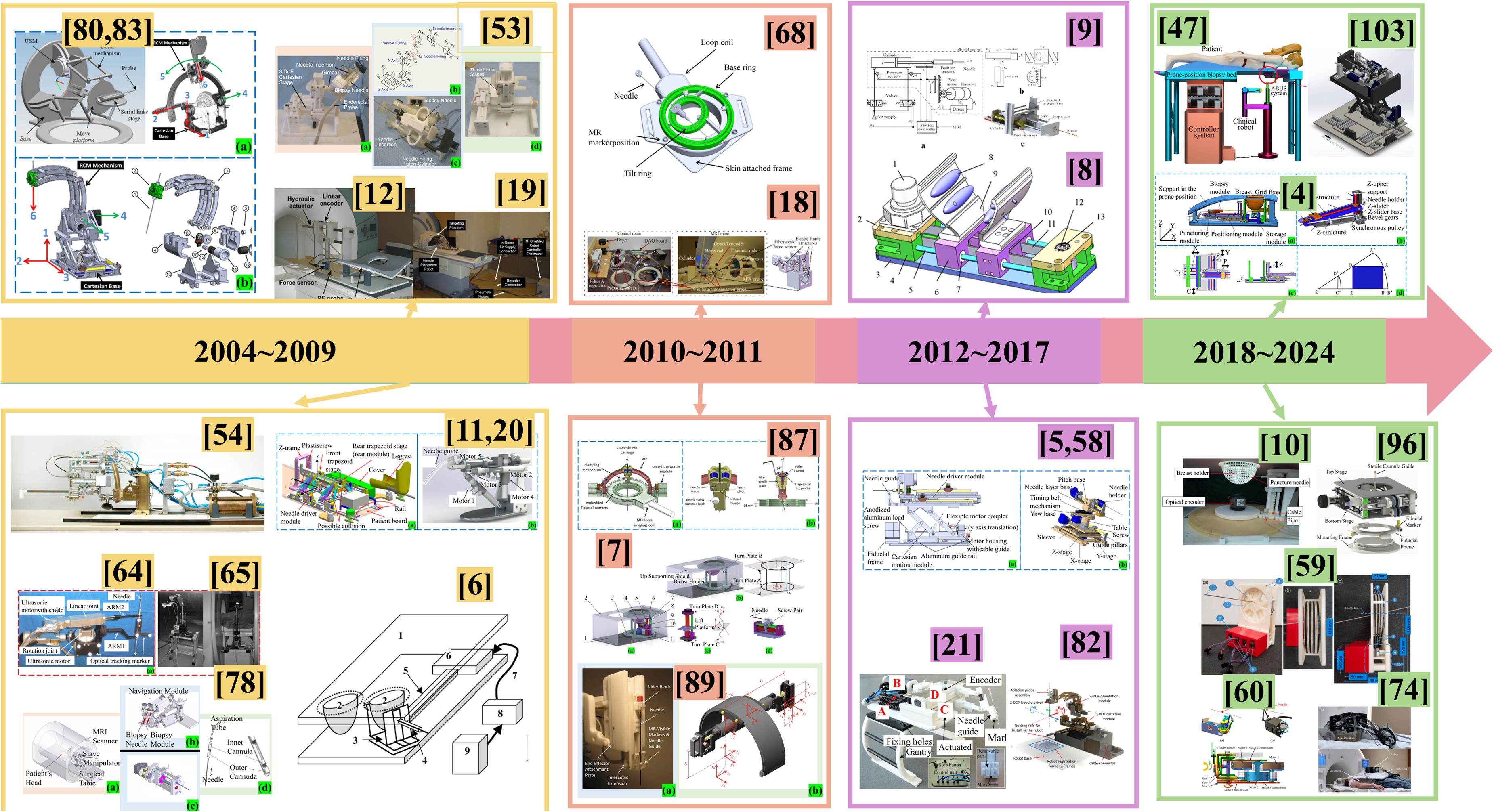
The development of interventional robots guided by MR.
MR-guided breast interventional robot
In 2004, the stereotactic device designed by Arthur G. Erdman and his team for minimally invasive breast surgery, which resembles a “large box,” as described in the literature,23–29 achieves high automation and precise control through a simplified design (see Figure 2). 6 This device employs an ultrasonic motor to facilitate precise positioning and angular adjustment of the probe. It incorporates four positional degrees of freedom (DOFs) for rotation and fixation of the probe, along with an additional DOF for controlling the depth of needle penetration. Although the device's high degree of automation minimizes radiation exposure risks typically associated with manual operation by physicians, the use of an ultrasonic motor can induce artifacts and positioning errors in MR images. Moreover, the high-frequency electrical signals generated during the operation of the ultrasonic motor may diminish the MR signal-to-noise ratio, potentially compromising the accuracy and safety of the procedure. The experimental results show that the device has good repeatability and stability, can complete probe positioning in less than 50 s, and can maintain a repeatability of less than 1 mm. However, the backlash of the rotating joint can lead to an error of up to 5 mm in the position of the probe tip. Consequently, future design enhancements must address these technical challenges to enhance the clinical utility of the device and ensure patient safety.
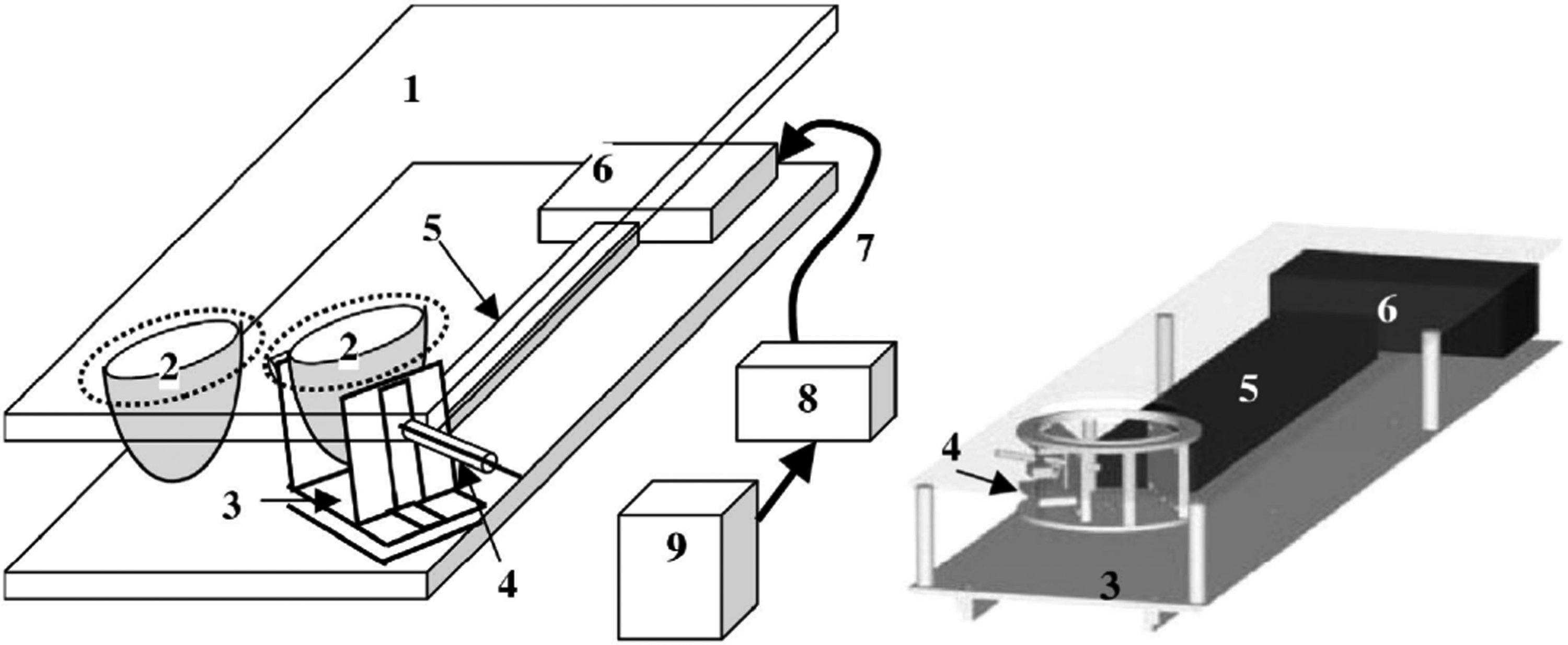
Schematic representation of the device: (1) elevated patient couch part of the device, (2) representations of patient breasts, (3) rotating probe stage, (4) probe insertion and angulation mechanism, (5) telescoping shafts, (6) ultrasonic motors, (7) motor control and power lines, (8) control CPU and digital-to-analog converter, (9) motor controllers. 6
Rebecca Kokes et al. developed a hydraulically driven, single DOF robotic system for Radio Frequency Ablation(RFA) of breast tumors (see Figure 3). 12 This system administers radiofrequency current via a needle electrode that penetrates the skin to effectively necrotize tumor tissue. 30 The structural design incorporates low-conductivity carbon fiber materials to construct both the slider and a fixed bottom rod, serving as a reference position. This choice of material ensures MR compatibility and the nonmagnetic nature of the device. As the piston rod is actuated, both the top carbon fiber rod and the slider advance, propelling the RFA probe, which is rigidly attached to the slider. Although hydraulic and pneumatic drive technology is conducive to maintaining a high signal-to-noise ratio and ensuring smooth operation and accuracy, this method also faces the disadvantage of working process instability. 31 The single DOF may lead to discrepancies between the robot's actual piercing position and the targeted focus within biological tissues, thereby limiting the accuracy of biopsies. Moreover, MR compatibility issues arise in the vertical motion direction, potentially complicating operation maintenance. These limitations the need for design improvements to enhance both the functionality and clinical applicability of the system.

Single DOF MR-guided interventional system used in the experiment. 12
Bo Yang et al. proposed a long transmission line pneumatic position minimally MR-guided breast interventional robot. 18 It operates on the same principle as,19,32,33 and both use the pneumatic drive mode.34–40 Bo Yang et al. described the design and control of a movable single DOF needle-driven robot, as well as the feasibility of using a long pneumatic transmission line (9 m) from the MR outdoors to the equipment inside the magnet to avoid image distortion. At the same time, the device employs polymer materials to avoid the influence of strong magnetic fields. To measure the insertion force, the slider is used in conjunction with the bearing, and a three-dimensional optical fiber force sensor 41 is installed beneath the slider (and the RFA pin is installed on the force sensor). Valves, 9 m transmission lines, and pistons (see Figure 4) round out the pneumatic drive system. The Stribeck friction model is used to describe the change in the friction force at low speeds. To verify the effectiveness of the controller, a simple friction model is designed and used in the simulation to test the robustness of the controller. Finally, the author designs a controller using SMC (sliding mode control) technology to overcome the adverse effects of friction on the system. They tested the system using a 3.0 T MR device and verified its MR compatibility and performance in an MR environment. Based on a long transmission line, this MR-guided pneumatic system with a single DOF achieved good results. Compared with the traditional motor, it has higher accuracy, is cleaner and will not cavitate compared with the hydraulic drive and will not cause a decrease in the signal-to-noise ratio when moving compared with the ultrasonic motor. Air is compressible and capable of fast impedance and control. However, the limitation of the system is that the pneumatic drive will have some instability, and the control model using the approximate first-order system model is not very accurate.
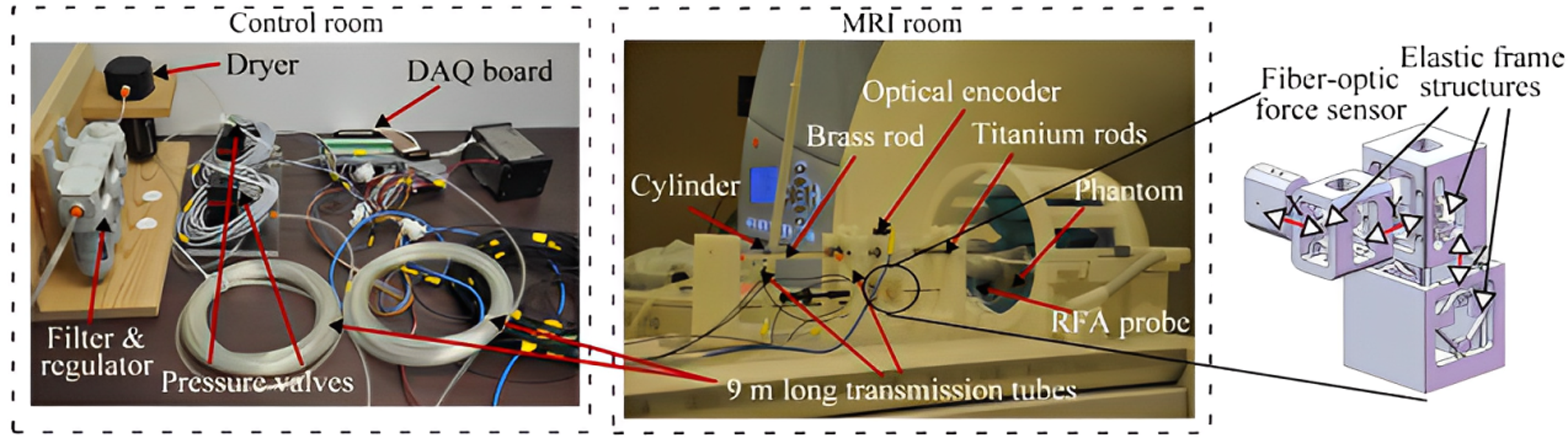
MR-guide single DOF prototype pneumatic system. 18
Tendon driven MR-guided interventional robots have the characteristics of high precision and small size in interventional surgery.42–44 Shan Jiang et al. proposed a tendon-driven minimally invasive surgical robot for breast surgery that consists of three tandem modules (the insertion module, lifting module and rotating module) (see Figure 5(a)). 7 The shell is composed of a base and a support cover. The patient lies prone on the device, and the breast tissue is placed inside a 3D-printed hemispherical cover (breast fixator). The insertion module is driven by a screw, and the needle is fixed to the slider (see Figure 5(d)). The lifting module is driven by a pair of screws between rotating plate C and bottom platform D (see Figure 5(c)). The rotating module is fixed to the base by the breast shield, and plate A and bearing are placed on the base and fixed to B, thus fulfilling the function of stabilizing the soft tissue (see Figure 5(b)). The robot system consists of an ultrasonic motor and tendon sheath model, and realizes a certain yaw angle by applying a tendon force to the C-plate. The application of tendon drives enables miniaturization design, which is particularly important in MR-guided minimally invasive robots. The driver is installed at the remote end, which enables the driver to be miniaturized, thus improving the accuracy of MR imaging. Compared to pneumatic drives, tendon driven robots avoid air compression problems. However, the accuracy of the tendon system robot is relatively low and needs to be compensated by the controller, and the compatibility issues with MR still need to be adjusted and further verified in a real MR environment. Finally, the transmission of tendon sheath and the performance of needle insertion were tested. The accuracy of the needle insertion was 0.68 mm. The reason for this error is that the experimental process is verified by a CCD camera, which is different from a real image system, and manufacturing and transmission will also cause certain errors.
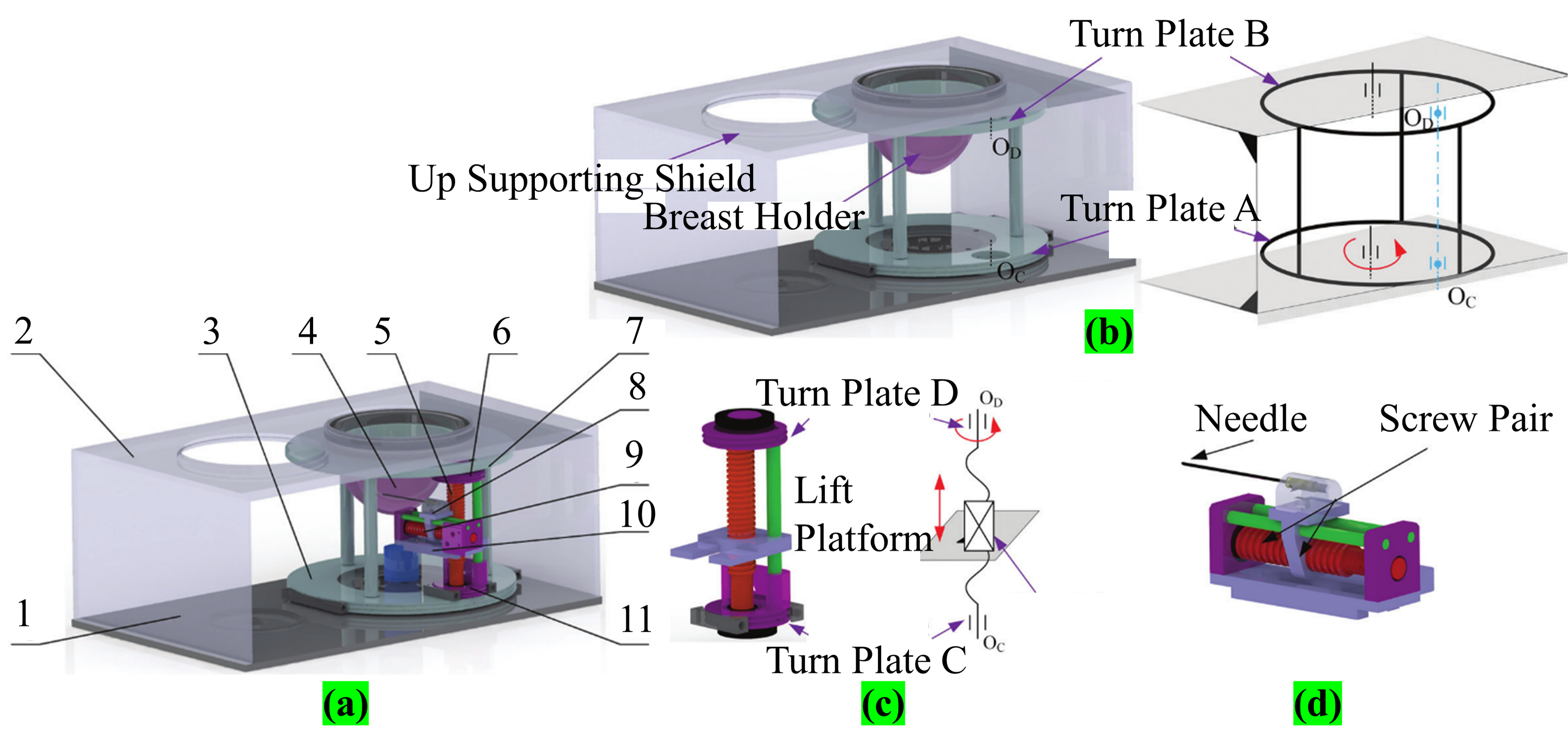
(a) CAD model of the robot: (1) base, (2) up supporting shield, (3) turn plate A, (4) breast holder, (5) lift screw, (6) turn plate D, (7) turn plate B, (8) needle insertion module, (9) insertion screw, (10) lift platform, (11) turn plate C; (b) rotary module; (c) elevate module; (d) insertion module. 7
Zhang et al. proposed a palm-shaped stable breast robot suitable for MR compatibility. 8 The robot (see Figure 6) drives the slider fixed on the guide bar mainly through a drive pulley system. The base consists of a pair of aluminum pulleys and carbon fiber rods, and the sliders are connected by belts for smooth movement. A palm-like device is mounted on the slider to hold the soft tissue of the breast (the palm-shaped device is adjusted by the slider). The air bag in the palm device is inflated to position the breast tissue and optimize its position (inflated by a compressor connected to a long tube and an electric valve system). However, the system contains multiple airbags, and it is uncertain how many need to be placed to achieve the optimal solution. In addition, the control method is an open loop, and the inflating state of the airbag cannot be accurately determined. Therefore, to accurately control the airbag, it is necessary to install a pressure sensor on the equipment and design a closed control system for the corresponding system.
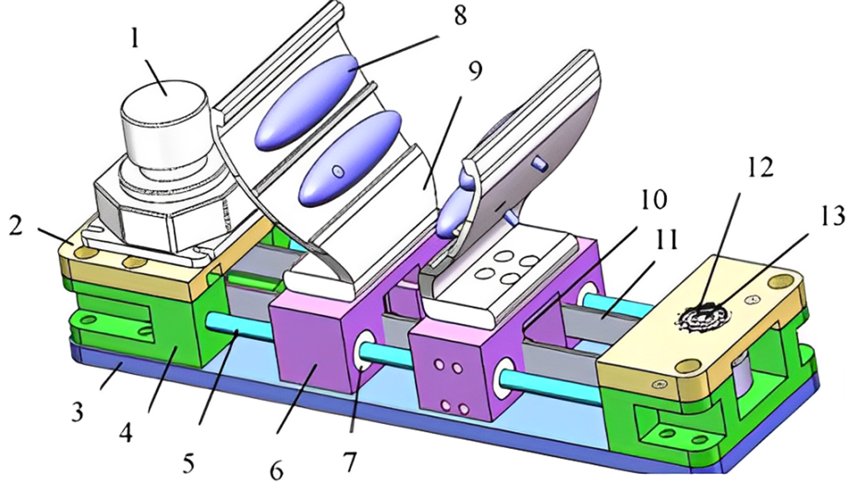
Components: (1) piezoelectric motor, (2) motor base, (3) bottom base, (4) pulley base, (5) carbon fiber rod, (6) slider, (7) sleeve, (8) silicon air bladder, (9) palm plate, (10) aluminum belt platen, (11) belt, (12) ceramic bearing, (13) pulley shaft. 8
David et al. proposed a 3 DOF robotic system design for MR-guided breast biopsy. 9 The system uses a double acting cylinder to drive the needle. The control system is composed of three modules, namely, positioning module, driving module and control module. The positioning controller is used to aim the needle at the lesion, the drive module is powered by the cylinder, and the control module is used to optimize the insertion of soft tissue (see Figure 7(a)). Figure 7 shows a partial diagram of how the needle positioning focus is achieved. The X-axis transmits motion to the joint via a screw (see Figure 7(b)). The Y-axis provides support for the biopsy gun through two sliders, and the matching of the rack and pinion passes the transmission to the joint. Figure 6(c) depicts the proposed mechanism. The PID control algorithm was adopted in the robot controller system, and the x-y experimental results were used only along the insertion needle axis and the alignment of the lesion, and the accuracy was less than ± 0.4 mm. However, the system is driven by a pneumatic device, and the air is compressible and becomes unstable due to temperature.

(a) Schematic representation of the robot and motion control system; (b) free body diagram of components used in the x–y platform; (c) details of the insertion joint mechanism. 9
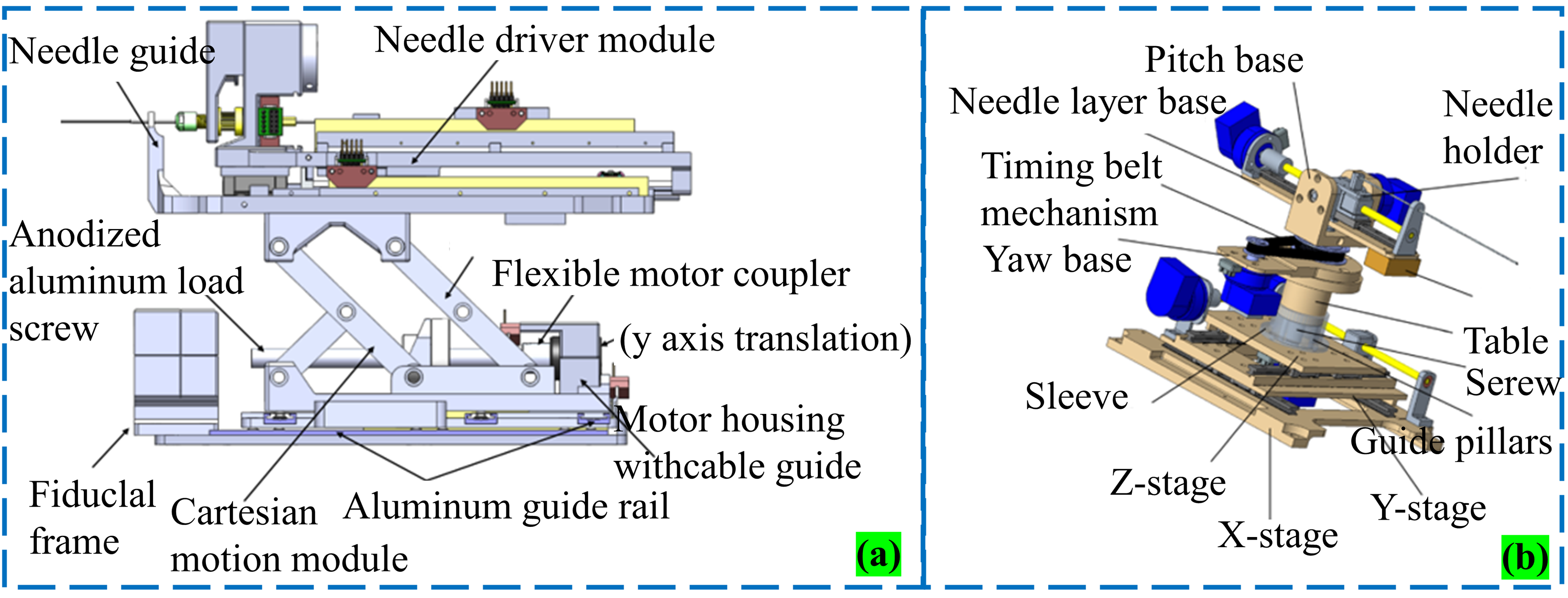
A series of MR-guided breast interventional robots have been developed, but these robots usually occupy a large area, or the intervention needle position adjustment range is too large, resulting in space utilization problems.6,45,46 However, robots using the pitching mechanism mode only need to slightly adjust the position of the needle to achieve the point of focus. Lu et al. proposed the design and control of a 7 DOF MR-guided prone breast robot (see Figure 8(a)). The robot is mainly composed of a positioning module, intervention module, biopsy module and storage module. The workflow is as follows: first, focus imaging is performed by MR, after which the breast tissue is stabilized by front and rear pressure stabilization plates (to prevent excessive breast movement); Then, MR imaging is used to determine the final intervention path by comparing the two images, and finally, the intervention point is precisely located by adjusting the module (see Figure 8(b)), and the biopsy module is placed at the end of the execution (see Figure 8(c)). The module has the freedom to realize needle insertion and withdrawal. Compared with traditional mechanisms, robots have compact structures and small adjustment ranges. The adjustment range of the traditional robot is shown in Figure 8(d) as rectangular ABCD, while the pitching mechanism only needs to adjust the length of C'D’ to achieve short-term attitude adjustment. 4 Compared to other pitching mechanisms, the robot is smaller, 7 DOF can achieve a variety of adjustments (more stable, high-precision adjustment, avoid critical organization, etc.), and is able to operate flexibly in small Spaces. Finally, the motion control experiment is carried out, and the positioning error of the robot is 0.37 mm. The experiment of the robot is still in the experimental stage, the soft tissues are all replaced by silica gel, and there are certain limitations in the lack of research on animal soft tissues. The breast of the object of this experiment was replaced with silicone, and the breast prosthesis made of silicone could not fully reflect the deformation characteristics of the breast tissue. The same experiment can be conducted on animal tissue in vitro, and the data of the prosthesis and three-dimensional tissue can be compared and analyzed.

(a) A 7 DOF compact Cartesian coordinate breast interventional robot model; (b) the design of the pitching mechanism; (c) the DOF of the positioning module and puncturing module; (d) comparison of two workspaces. 4
Jiang et al. proposed a 3 DOF semiautomatic MR-guided tandem mechanism interventional robot suitable for breast biopsy surgery (see Figure 9). 10 In the MR environment, the DBSD(Dedicated Breast Support Device) breast device mechanism was proposed to avoid low accuracy due to excessive breast fluidity. The robot is driven by an ultrasonic motor and two turntables A and B provide two degrees of rotational freedom. The piercing movement is realized in a straight line through the nut mechanism on the nut platform. However, because the experiment is in the theoretical stage, the actual situation may be slightly biased. The experiment showed that the average positioning accuracy was 0.7 ± 0.04 mm. The reasons for the error include mechanical manufacturing, visual system and positioning algorithms. To improve the accuracy, it is necessary to address assembly errors, feedback errors, linear motion errors and encoder errors.

Composition of the DBSD robot structure. 10
Sergi and Jorge proposed a new type of clinical robot designed to assist radiologists in performing 3D US-guided breast biopsies. Although this is an US-guided breast interventional robot, the system can improve the ability of the material to adapt to the MR environment, and the intervention accuracy can be improved. The robot has a 5DOF structural design and provides a needle guide through the linear movement of the end-effector, thereby improving the accuracy of manual insertion, as shown in Figure 10. 47 The effectiveness of the robot is verified by kinematics modeling of the robot and the simulation experiment of the collision-free path algorithm. The results showed that the success rate of robot-assisted biopsy was higher than that of traditional US-guided biopsy, and a targeting error rate was lower. This preliminary study shows the potential of robots in breast biopsies, and future work will focus on improvements in size, materials and manufacturing processes to enable more practical prototypes. Anastasia Antoniou et al. developed a method to evaluate the performance of an MR-guided needle biopsy robot, using an agar-based breast model and caliper measurement, through laboratory and MR environment tests, and the results showed that the maximum error of linear motion up to 10 mm was 0.1 mm. 48 Needle navigation has been successfully aligned in phantom bodies and with various biopsy targets in both laboratory and MR settings. This method has been proven to be highly accurate and reliable for needle navigation alignment and biopsy target localization. This method shows important application value in verifying the accuracy of MR-guided biopsy robotic equipment.

A new MR-guided 5DOF breast biopsy robot. 47
The technology of MR-guided breast interventional robots has developed significantly, and their research goals are focused on the flexibility of the robot structure, the selection of materials compatible with the MR environment, and the high-precision intervention. But they also differ in many ways, especially in the selection of drive systems and the diversity of structural design. For example, Erdman team uses ultrasonic motors to achieve high-precision positioning. 6 Kokes’ team used hydraulic drive to maintain a high signal-to-noise ratio, but their single DOF design limited the puncture accuracy. 12 Bo Yang team used long transmission lines driven by air. 18 Jiang et al. proposed a tendon-driven minimally invasive surgical robot with high precision and small size. 7 David team’s 3 DOF robot system is driven by two cylinders. 9 Although there are connections and differences in the research of various teams, they design robots with the same philosophy, focusing on system stability and high-precision intervention.
MR-guided prostate interventional robot
Robot-assisted technology49–51 has been widely used in minimally invasive surgery. Krieger et al. proposed a 2 DOF MR-guided robot for transrectal prostate intervention. 35 In 2008, Fischer et al. designed an MR-guided pneumatic robot for transperineal prostatic intervention. 19 They do this by spraying radioactive seeds to locate the needle for treatment, without the need to move the patient out of the imaging area. The movement diagram of the system is shown in Figure 11. Modules 1, 2 and 4 are adjusted in the X, Y, and Z directions, respectively, while modules 3 and 5 are rotated and adjusted by aligning the needle axis to finally achieve intervention. Fischer et al. proposed two decoupling motion models. One of them is that the vertical plane movement can be a 15° pitch, lifting method for the traditional plane sports shear lifting mechanism, through the rear mechanism to increase stability. The other achieves linear and rotational motion in the horizontal plane by combining two linear motions. It can be moved bilaterally (relative to the center) compared to the front shear mechanism. In addition, the kinematic requirements, workflow, positioning and placement accuracy evaluation of the system are described in detail, and the results of preliminary tests are presented, including the robot's Signal to Noise Ratio (SNR) loss of less than 5% under standard MR sequences and its ability to accurately align targets in three-dimensional space. The workflow of the whole system, from planning to implementation to feedback adjustment, is completed under the real-time monitoring of the surgeon, ensuring the safety and effectiveness of the operation. Because the system is pneumatically driven, there will be a phenomenon of system instability due to the compressibility of air.

The robot has 6 DOF for needle insertion and can add more specialized end effectors. 19
H. Elhawary et al. proposed a 5 DOF prostatic interventional robot (see Figure 12(a)), in which 3 DOF were composed of a Cartesian platform (see Figure 12(c)). The probe and intervention module are connected via a universal joint. Owing to the universal-joint, the probe can adjust its position by pitching, yawing, and rotating and finally firing the needle in the manner shown in Figure 12(d). The specific motion diagram is shown in Figure 12(b). In the literature, 52 the development of MR-guided single DOF linear segments that can be used either independently or joined together to form a chain of motion has been reported. The piezoelectric ceramic motor is tightly coupled to the linear slider and then an optical encoder is installed to provide position information. 53 The robot uses power provided by a piezoelectric ceramic motor, combined with an optical encoder to ensure accurate positioning, and provides force feedback for needle insertion via a piezoelectric sensor. In this way, the device can be driven close to the patient and the image is stable without distortion. The experimental results show that the average error is approximately 2.3 mm, and the main reason for the error is that the needle and tissue model are subjected to stress, which may cause deformation and change the intervention path.
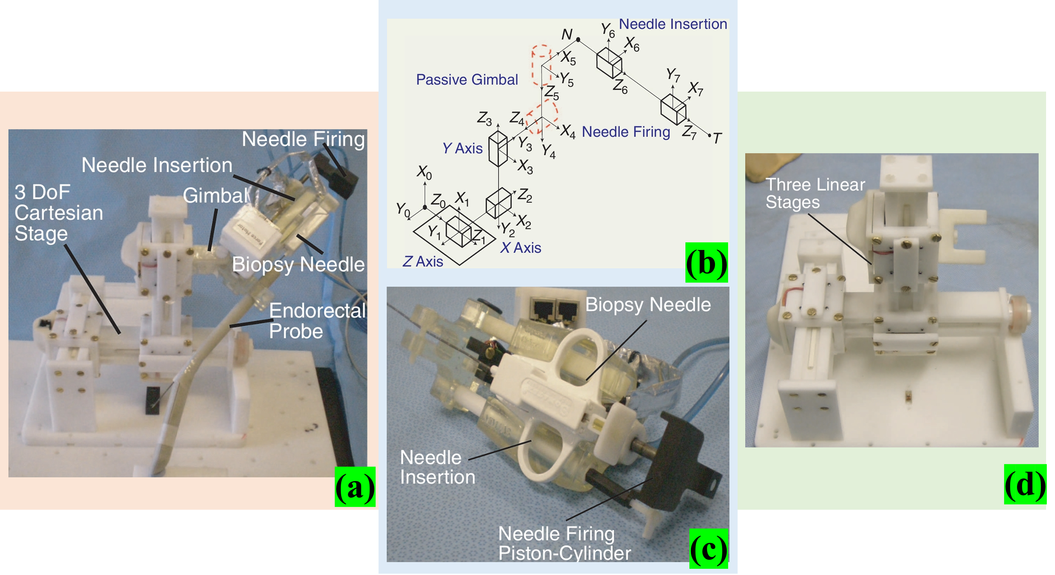
(a) 5 DOF robotic manipulator for transrectal biopsy of the prostate; (b) kinematic diagram of the robot; (c) 3 DOF Cartesian stage formed by connecting three single DOF linear modules together with a horizontal axis attached to a plastic bearing and placed on a support block to minimize deflection; (d) needle firing and translation stage. 53
Bosch et al. proposed a robotic system for MR-guided transperineal prostatic intervention. 54 The intervention device is pneumatically driven, and interventions are performed by rapidly inserting a needle. Its main features are fast needles, low tissue deformation and high accuracy during intervention, and buffering through a hydraulic cylinder setting (the intervention device can rotate and move in a straight line within 5 DOF). Radioactive seeds are fed into the target area by the tap of a needle (see Figure 13). To accurately locate and verify the position and path of the needle, high-resolution Balanced Steady State Free Precession (BSSFP)scanning and rapid 2D BSSFP image generation are performed during the procedure to track the needle tip position in real time. After the target location is reached, the surgeon manually places the fiducial gold marker at that location. Four gold markers were successfully implanted in the prostate of a patient with clinical stage T3 prostate cancer, demonstrating the feasibility of MR-guided needle insertion and seed delivery. The device is driven by air, and the system is unstable.

MR guided 5 DOF prostate interventional robot. 54
Eslami et al. proposed a 4 DOF MR-guided parallel robotic system design for transperineal prostate intervention (see Figure 14(a)). Most robotic materials are made from materials such as high-strength polycarbonate (20% filled glass), ABS and cast nylon, and machined by Computer Numerical Control (CNC). 20 Its main structure consists of two parallelogram mechanisms (trapezoidal platform) combined with the slider structure, and the trapezoidal platform at different positions can help the needle form different angles to avoid obstacles. The slider is equipped with a fiber-optic limit switch to prevent the slider from colliding with the support frame (the patient’s legs need to be opened when working). This structural design principle is a common type of trans perineal prostate biopsy robot system.55–57 Chen et al. proposed an MR-guided prostate interventional robot design with 5 DOF. Figure 14(b) shows a series-parallel hybrid system in which motors 1, 2 and 3 are driven in parallel and motors 4 and 5 are connected in series to control the angle. 11 The robot combines a programmable logic controller(PLC), a software application, and a pneumatic system to precisely position and navigate the needle during an MR scan, enabling high-precision interventional therapy. The control method of parallel robot is complicated, and the maintenance and modification are difficult.

Su et al. proposed a piezo-driven robot for MR-guided prostate intervention therapy. 58 The distance between the motor shaft of the clamping mechanism and the chuck shaft is adjusted by adjusting the tensioner rotation in the belt connection. The linear motor provides 2 DOF of movement for the system, using a shear mechanism for lifting and lowering (see Figure 15(a)). The phantom experiment validated the ability of the system to perform drive prostate biopsy placement with a spatial accuracy of 0.87 mm ± 0.24 mm. Compared with the pneumatic drive accuracy, the pneumatic drive accuracy has improved. 19 Shi et al. proposed a 6 DOF tandem prostate interventional robot based on MR, which evaluated the injection accuracy and positioned the intervention point with high accuracy through a Binocular Vision System (BVS). 5 Figure 15(b) shows the 6 DOF robot. The system consists of a 3 DOF Cartesian module and a 2 DOF Cartesian module, plus an intervention module. To simplify the movement, the 3 DOF Cartesian module is designed to decouple the movement, and the 2 DOF module adjusts the needle to improve accuracy. The synchronous belt transmits torque to improve the rotation resolution of the joint. The needle is driven by a nut structure. The driving device adopts ultrasonic motor with no electromagnetic interference, high precision and large torque. In particular, a simple general algorithm is proposed to estimate the camera coordinates of the needle tip, which solves the problem that cannot be detected by MR before the needle penetrates. In five trials, the maximum error was 2.383 mm and the maximum RMSE was 1.079 mm, indicating that the robot has good accuracy in the needle placement process in prostate intervention surgery. Although the author has explained that the algorithm can be used to estimate the coordinates of the needle tip and the accuracy of the experimental results meets the requirements of interventional surgery, the camera can only observe the surface points, but cannot see the interior. A mathematical model can be established and multiple data can be fused to estimate the location of the needle tip, and the accuracy should be improved again. My suggestion is that by building mathematical models of the needle and tissue, multiple data can be fused to estimate the position of the needle tip and further improve the accuracy.
Biswas et al. proposed a new compact prostate interventional robot with 4 DOF with MR guidance, 59 as shown in Figure 16. The mechanism consists of four discs containing small passive spherical joints that are moved by rotating discs composed of grooved profiles. With an initial needle insertion angle of ±15°, the mathematical and kinematic parameters of the mechanism design were determined to create a virtual prototype. However, the stability of the mechanism is poor, especially when the needle passes through the center of the double disk, the loss of directional friction contact and out of the center position. Liu proposed a cam-based automatic biopsy device for prostate glands used in MR environments. 60 The device requires only one actuator to perform all the actions during the prostate biopsy sampling process. Force analysis, sampling performance evaluation and MR compatibility tests were carried out. The results show that the automated biopsy device can easily complete tissue sampling and that its performance is comparable to that of existing commercially available manual biopsy guns. MR compatibility tests showed that the signal-to-noise ratio was reduced by 18.7% when the equipment was operating. The compact prostate robot they designed is characterized by high space utilization efficiency, high accuracy and improved device flexibility and maneuverability. The robot currently requires manual operation, is a semi-automatic device, and additional DOF needs to be added to this mechanism.
New compact prostate interventional robot with 4 DOF was developed with MR guidance. 59
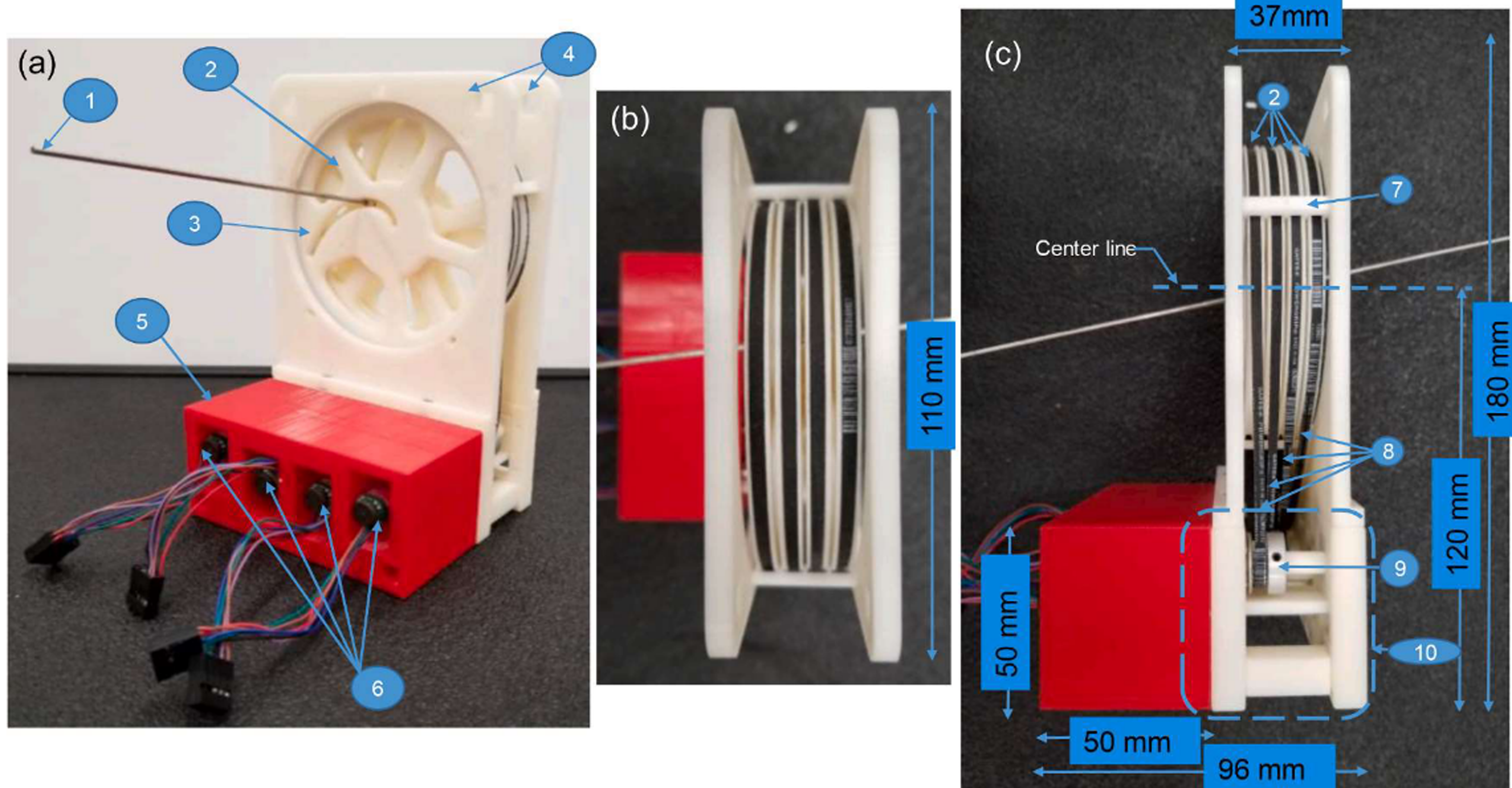
Liang et al. proposed a pneumatically driven prostate robot. This prostate interventional robot has a compact structure and a size of 23 cm × 12 cm × 11.5 cm, with 4 DOF, three of which are used for guiding needle position and rotation, and one for needle insertion. 60 Two degrees of planar freedom control the movement of the needle on the plane and the third DOF is used for plane rotation, both of which are driven by pneumatic stepper motors. The needle guide is located at the end of the robot and is supported by four rods, through which the needle is inserted into the prostate gland. Figure 17(a) and (b) show the CAD drawing of the robot and the photos of the object. Combined with these features, the robot provides a high degree of precision and stability when guided by MR imaging, making the prostate biopsy process more efficient and safe. After establishing the kinematic model, the author developed a user interface based on LabView to calculate the target position and generate the control signal. Experiments have shown that the needle can reach the target position with an accuracy of 1.3 mm. Under the 3 T MR canner, the signal-to-noise ratio change was less than 5%. Pneumatic stepper motor drive systems have advantages in terms of size and compactness, but there may be some limitations, such as response speed and accuracy affected by changes in air pressure and temperature. These possible impacts and their solutions are not discussed in detail.

A pneumatically driven prostate robot in a 3TMR environment. 60
The technology of MR-guided prostate interventional robots has been significantly developed, and most of their studies have robots with 4–6 DOF, which are designed to achieve complex motion control. Many robotic systems integrate force feedback and position feedback functions, which are monitored and adjusted in real time via sensors and encoders to improve the needle insertion accuracy and surgical results. But the drive systems of these robots and the type of robot construction are different. For example, the parallel robot structure proposed by Eslami et al., using slider and parallel quadrilateral mechanism, has good flexibility and angle adjustment ability. 20 The series-parallel hybrid system proposed by Chen et al. combines PLC and pneumatic system to realize high-precision needle positioning and navigation. 11 Although there are connections and differences between the various teams’ studies, the researchers are committed to studying prostate interventions with high precision.
MR-guided liver interventional robot
The use of robotic arms in interventional surgery based on MR is relatively common.6,49,61–63 In 2010, Sato et al. developed an open two-arm, 2 DOF robotic arm (operated by a physician). The robot confirms the focus position by combining MR images, a robotic arm coordinate system and an optical 3D tracking system. As shown in Figure 18, 64 at work, one arm is fixed (connected to the needle), while the other arm is driven by a motor to operate the other end of the needle. Because the system uses an ultrasonic motor to avoid the impact of the signal-to-noise ratio, the control box is located outside the MR scanner. Although the robot has helped doctors improve surgical accuracy, the system still has major limitations. Its large size requires the cooperation of doctors, which largely does not solve the problem of radiation exposure for doctors and patients. In 2008, Hata et al. proposed an MR-guided robotic arm with remote motion center control where doctors and robots can interact to select the best needle trajectory. 65 The base of the system has 3 DOF (the end effector is attached to it), is positioned laterally under the patient bed, and uses a passive 2 DOF arm to hold the needle. Through the drive of the base and the arm, combined with the operation of the doctor, the 3 DOF active movement and 2 DOF passive movement are used to find the best path of the intervention focus. The authors developed a control method that combines virtual remote center of motion (RCM) and a collaborative human-machine interface (SHMI). 66 The authors evaluated the MR compatibility, accuracy and practicality of the robot through experiments. Despite some errors (the average error is less than 3 mm), the robot can significantly improve the efficiency and accuracy of doctors in the treatment of liver tumors.

Song et al. proposed a needle guide template adapted to MR environment and designed an interventional robot with a double-ring RCM mechanism guided by MR.67,68 Interventional robot with a double-ring RCM mechanism advantage of this system is that it is relatively compact, with no joints (reducing the impact of stiffness damage) and only improved ends. It includes a 2 DOF needle positioning mechanism, which mainly uses piezoelectric motors to drive the rotation of the upper and lower rings and the drive of the needle, as shown in Figure 19. The mechanism is attached to the human skin, with the large ring on the base and the small ring at a 20° angle from the large ring (to facilitate needle rotation). Due to attachment to the skin, errors due to breathing can be reduced to a certain extent, and the authors assessed the optimal intervention location. However, due to the use of rapid prototyping equipment, the accuracy of the system is low and the manual angular resolution is still limited. The fact that the experiment was conducted without breathing is not convincing. The needle may be deformed in contact with the tissue during intervention, resulting in deviation of the intervention path. In addition, the system has not yet realized fully automatic needle intervention.
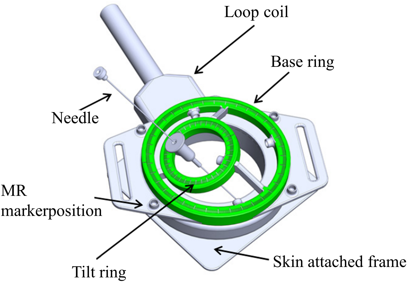
CAD model of a proof-of-concept model with a loop-shaped imaging coil. 68
Based on the 3 DOF concept, 69 Franco et al. proposed a 4 DOF hybrid structure (series-parallel combination) interventional robot for MR-guided laser ablation of liver tumors. Compared to the previous needle handling space (with added rotation), the system operates using pneumatic plastic cylinders, allowing for high-precision control of the piston, combined with MR images to determine the intervention path. It is common for semiautomatic robots to assist doctors in performing puncture surgery.70–73 The robot (see Figure 20) is fixed to the bed, has modules for fixing the gantry frame, and combines MR images to automatically align the focus. During imaging and needle insertion, mechanical ventilation is used to minimize liver movement, 21 which is then manually inserted by a physician. Although the system obtained high accuracy using the TDC scheme used by the author, its tracking performance was poor and difficult to estimate, and the model used in the experiment was not a real liver, which had certain limitations. The experimental results show that the mean in-plane error is 2.9 mm, the standard deviation is 1.4 mm, and the maximum value is 4.8 mm. The SNR change caused by the robot is less than 5%. The intervention error is large, but the author explains the cause of the error and the operator's influence on its operation. The operation time of the system is also relatively long, so it should be improved to shorten the operation time.

Prototype of the needle-guiding robot (cylinders are A, B, C, D). 21
Huang et al. presented a compact 4 DOF body-mounted MR conditional robot that consists of a support plate, a transmission system, a drive system (including an air motor, an optical encoder and a limit switch), and a needle guide (see Figure 21). 74 The robot platform consists of two stacked right-angled XY stages, each with two DOFs for easy needle guidance. The experimental results show that when the insertion depth is 80 mm, the insertion error of the robot-assisted needle is 2.6 ± 1.3 mm. Although the needle tip error meets the requirements of most clinical scenarios, the robot workspace is limited by a maximum insertion angle of 30°, which is not flexible enough.
A compact 4 DOF body-mounted MR conditioned robot. 74
The technology of MR-guided liver interventional robots has advanced significantly, and most of the types of robots researcher study are semi-automated designs that rely on physician assistance. However, the researchers’ robots differ greatly in their structural design concepts. For example, the 4 DOF body-borne MR conditional robot designed by Huang et al. has a compact structure and adopts a superimposed right angle XY platform for needle guidance. 74 The double-ring RCM mechanism proposed by Song et al. involves the robot, which uses piezoelectric motors to drive rotation and realize needle positioning. 68 Although there are different directions in their research, they are all committed to reducing human-induced errors and improving the accuracy of intervention.
MR-guided neural system interventional robot
In many neurosurgical procedures, as noted,75–77 brain swelling, cerebrospinal fluid leakage and other factors can cause brain displacement, which greatly increases the difficulty of surgery. In 2007, Raoufi et al. developed a robot for positioning and advancing biopsy needles during brain biopsies (which can be expanded to other similar neurosurgical procedures), as shown in Figure 22(a), where the robotic arm is mounted on a bed and the biopsy needle is fed via a drive module. The control position module of the system is a 6 DOF parallel mechanism (see Figure 22(b)) with six robotic arms connected to the universal joint and spherical pair on the plate. The parallel mechanism is adjusted by six lead screws (driven by an ultrasonic motor). The drive module of the biopsy (see Figure 22(c)) consists of an upper and lower fixed frame and a rotating module, and the lead screw nut can be moved up and down. The biopsy needle consisted of two cannulae (see Figure 22(d)), with the inner cannulae driven and rotated by a belt pulley system and the outer cannulae holding the needle in place by a jacket clip and a needle clip. 78 A robot uses a parallel mechanism, and its compact structure is more flexible than that of a series mechanism. Because of the simple mechanical structure and high signal-to-noise ratio, the image quality is less affected. Of course, the limitations of the system are obvious. The robotic system consists of a master controller, six ultrasonic motors, two ultrasonic motors to provide the propulsion and rotation functions required for needling, and slave manipulators associated with the MR scanner coordinate system. Control of the surgical tool is achieved by using a reverse kinematics based method to calculate the desired length of each bar and six feedback encoders to measure the actual length. Since the device is semiautomatic, it is not possible to significantly reduce the workload. It has a relatively high radiation impact on doctors and patients compared to fully automated medical devices.

(a) The slave manipulator inside the MR scanner; (b) 3D model of the slave manipulator; (c) the biopsy module and its main components; (d) a typical brain needle biopsy. 78
Ken et al. proposed a 6 DOF robot for stereotactic neurosurgery, 49 and other research organizations have also proposed a series of MR-guided interventional robots.63,79 Hong et al. proposed a minimally invasive surgical robot suitable for neurosurgery in MR environment, as shown in Figure 23(a). 80 The system uses a delta parallel robot as the bottom, combined with a 2 DOF series robot.81,82 The tandem mechanism has two degrees of rotation freedom to control the pitch and angle positioning, which is ultimately pierced by an ultrasonic motor. In addition, rigorous MR compatibility testing ensures that the device does not compromise MR image quality and patient safety. Ultimately, the robot is optimized to adapt to the limited space environment, with a good user interface and task-oriented design features, with the goal of achieving automatic, accurate and efficient neurosurgical operations. Li et al. proposed an MR-guided Deep Brain Stimulation (DBS) robotic system. 83 The first kinematics of the robot mimicked the Leksell stereotactic framework (see Figure 23(b)). The system, as shown in Figure 23(c), is implemented through the combination of a 3 DOF Cartesian motion module and a 2 DOF RCM mechanism module. Modules 1, 2, and 3 achieve Cartesian orientation of motion by means of a scissor lifting mechanism (driven by a linear piezoelectric motor), modules 4 and 5 are two rotational DOFs (driven by a belt device), allowing 0–90° adjustment (see Figure 23(d)); And module 6 is the final piercing freedom. The mechanism enhances the compactness and rigidity of the structure through the parallel mode, but because the motor itself may cause signal problems, the author does not start from this point of view, leading to certain problems in the expected intervention path. At present, this mechanism is applied to the placement of DBS electrodes, which has certain limitations in MR-compatible surgical applications.

(a) Three-dimensional CAD model of a robot for neurosurgery; (b) equivalence of the DOF of a traditional manual stereotactic frame; (c) the proposed robotic system; (d) exploded view of the RCM orientation module, showing (1) instrument/electrode, (2) headstock with cannula guide, (3) parallel linkage mechanism, (4) manipulator base frame, (5) flange bearings, (6) pulleys, (7) timing belts, (8) rotary encoders, (9) encoder housings, (10) pulleys, (11) eccentric locking collars, (12) rotary piezoelectric motors, (13) manipulator base.80,83
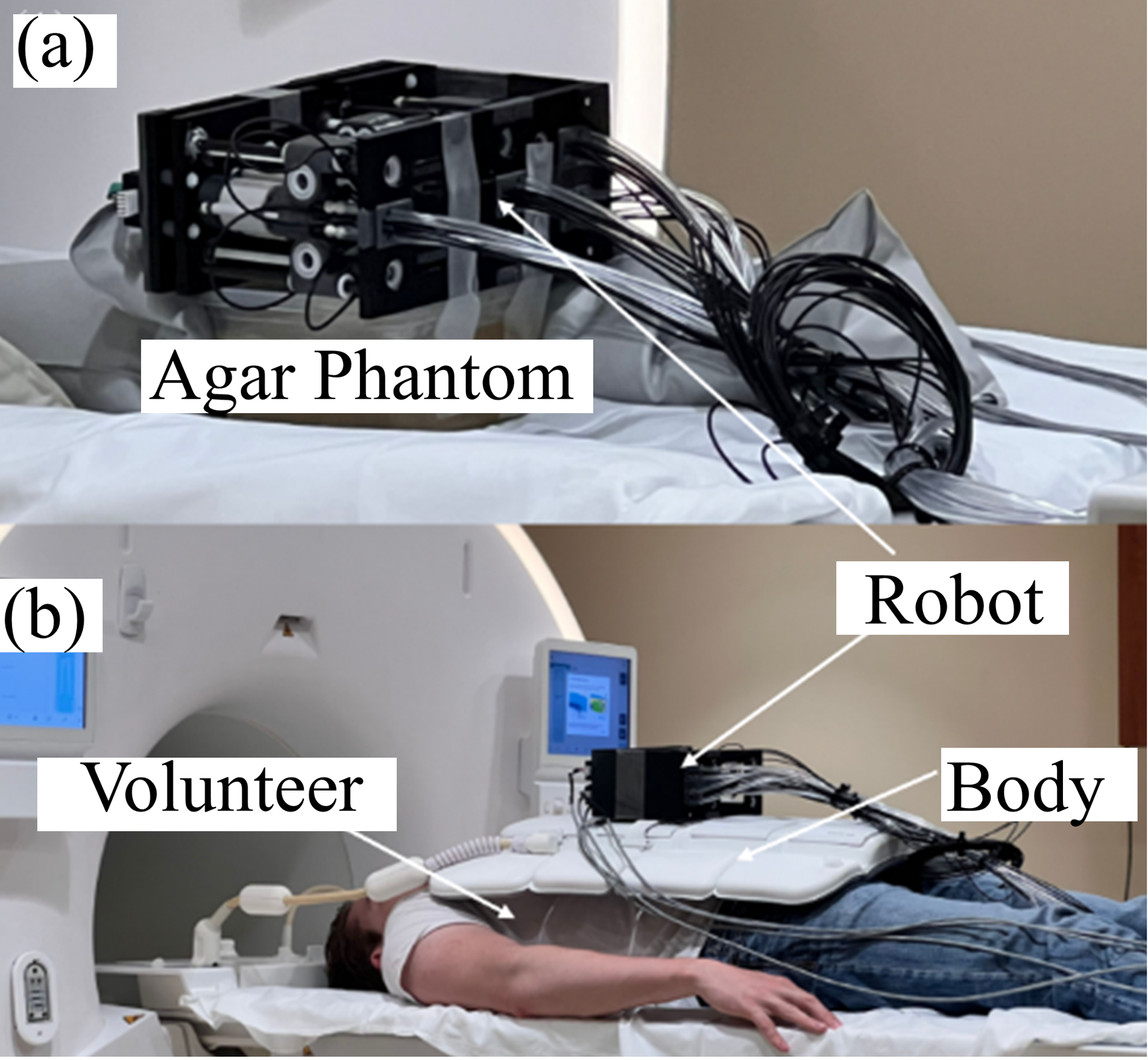
Niravkumar et al. proposed an MR-guided stereotactic frame robot design (driven by an ultrasonic motor) for the treatment of brain tumors. For early principles and conceptual models, see. 84 As shown in Figure 24, the system consists of three modules, one of which is a Cartesian coordinate platform for RCM positioning, another module head to find the intervention path through 2 DOF rotation and insertion, and another 2 DOF module to realize the final intervention point of the needle through rotation. 85 Through preclinical trials, in the gel phantom, the system demonstrated an average displacement accuracy of 1.39 ± 0.64 mm and a rotation accuracy of 1.27 ± 0.56°. In the 10 pig models, these values increased to 3.13 ± 1.41 mm and 5.58 ± 3.59°, respectively, resulting in a 10.3% reduction in the maximum (SNR). The experiment showed that the system was able to accurately place the ablation tool under real-time MR monitoring and monitor the ablation process. The authors will conduct human trials to further optimize the system and explore its clinical feasibility in various neurosurgical interventions.
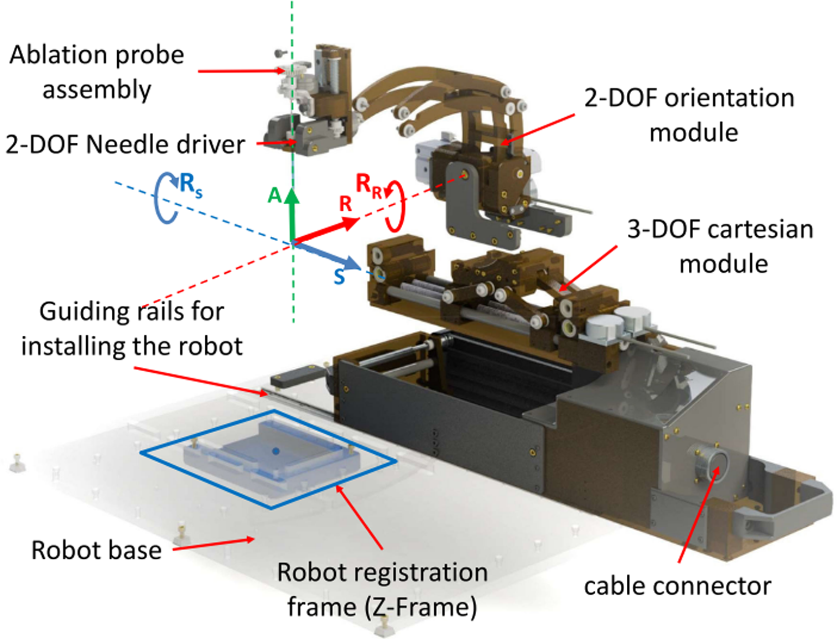
CAD rendering of a clinically optimized neurosurgery robot showing all three modules of the manipulator along with the robot registration frame and the coordinate system. 85
He et al. proposed a stereotactic neurosurgical robot, as shown in Figure 25. 86 The system uses a five-bar linkage design, which has higher positioning accuracy, lower inertia and greater structural stiffness. At the same time, it is equipped with a manual and robot-controlled instrument seeker that effectively counteracts the load introduced by motion deviating from the operating range. To keep the robot compact, the system uses ceramic bearings and high-performance thermoplastic materials to support the joints, and uses a friction ring braking mechanism to lock the four proximal joints. The results show that in 11 attempts, the average errors are 2.2 mm and 1.7 mm, respectively. In addition, a registration method for a robot in an MR environment based on wireless identification is proposed, and the accuracy of the whole workflow and the clinical feasibility of the system are verified via experiments. This technology is expected to reduce surgical errors and improve the surgical efficiency and safety.
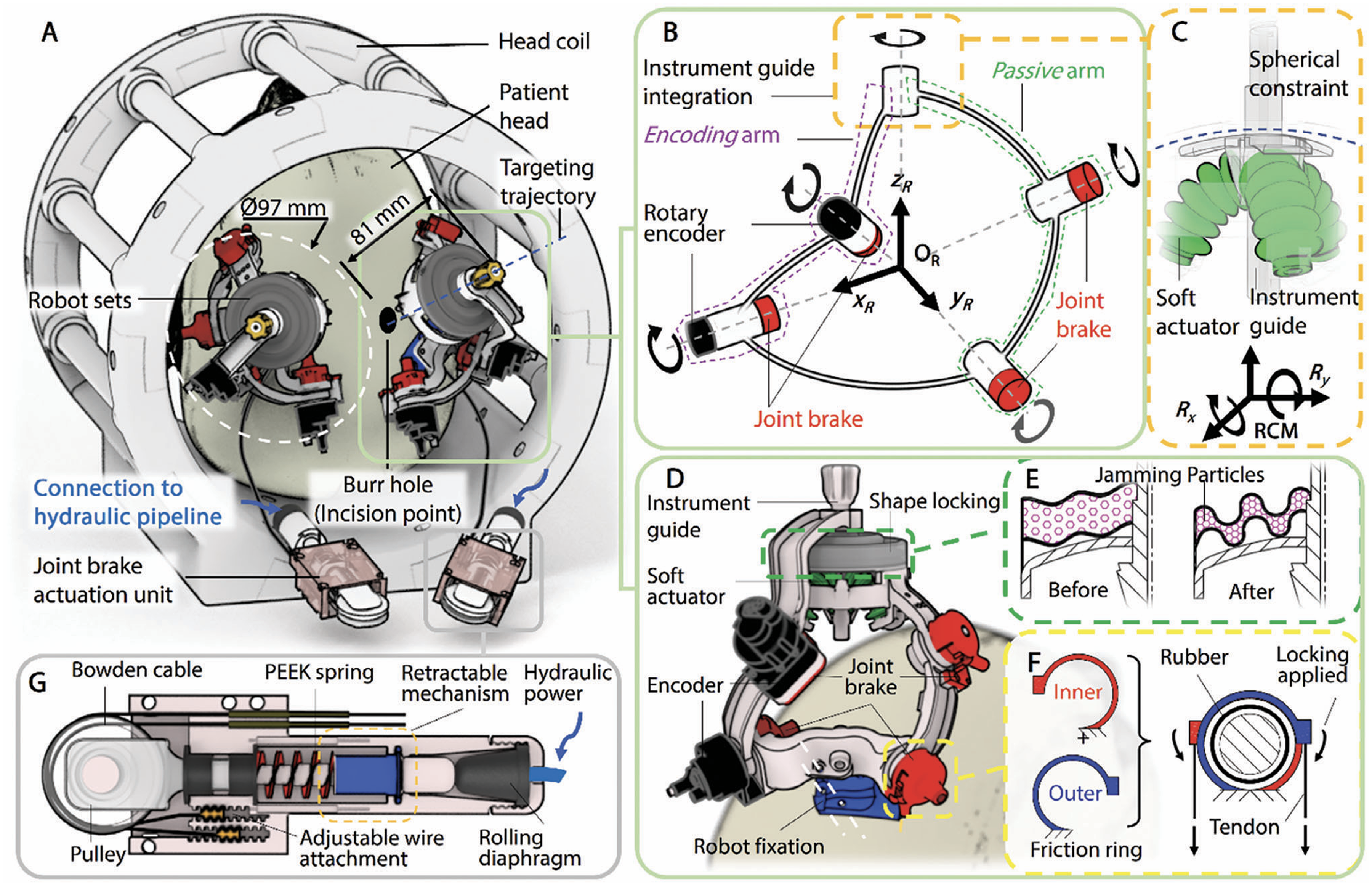
A novel stereotactic neurosurgical robot and its operating principle. 86
In neurosurgery, brain displacement caused by brain swelling and cerebrospinal fluid leakage has greatly increased the difficulty of surgery. The researchers designed these MR-guided neurointerventional robots, most of which have structures involving multiple DOFs, usually in the range of 6 DOF, with the aim of achieving complex motion control and precise positioning. However, there are significant differences in their driving methods, structural design and experimental verification methods.
Other MR-guided percutaneous surgical interventional robots
In 2013, Wu et al. developed a robot for multiprobe cryoablation localization of the abdominal region, which is compatible with the MR environment. 87 The system can contain three cryoablation probes, as shown in Figure 26(a). It is mainly composed of a spherical mechanism and a circular base. The spherical mechanism shown in Figure 26(b) simulates the motion of the wrist to achieve 2 DOF of the probe. In this spherical mechanism, four of the five rollers are at the top and one is at the bottom, and angular motion around the RCM near the insertion point is achieved by a rotating drive. A slider consisting of a manually released probe is constrained through the bearing (reducing clearance and friction). Thumb screws are installed on the slider to enable 3D positioning of the probe and guarantee image quality through shielding. 88 The robot is compact and can be used repeatedly in a small space in an MR environment to achieve the desired goal. However, the system is still in the principle stage. In addition, the equipment uses a miniaturized and easily replaceable motor module for rapid disinfection and reuse. In a 3 T MR environment, a number of experiments were conducted to verify its compatibility and performance, and the results showed that the maximum SNR change was only 4%, while the positioning error of the device itself was less than 1°. Finally, through the gel needle positioning test, it was confirmed that the robot was able to achieve an average aiming accuracy of 2.0 mm. Although the accuracy of the system meets the requirements of interventional surgery, the operation process is complicated and needs to be simplified.

(a) The device has two automatic DOFs for probe positioning and one manual DOF for probe release; (b) three tracks on the frame prevent the probes from crossing. 87
Christofoou et al. developed a universal 5 DOF robotic arm adapted to the MR environment. 89 The system immobilizes a robotic arm on a curved track, using unique structural and kinematic elements similar to ring bows that allow for increased rigidity. 90 There is a tool on one end and a handle on the other. The needle is manually driven by a cable mechanism, and the tip adopts a sleeve structure. 91 The end effector is shown in Figure 27(a). The Cartesian coordinate frame of the operating system is fixed to the ground and the intervention is performed in conjunction with the clinician's manual operation. The arc mechanism of the system plays a good supporting role. Although manual driving reduces the limitations and costs of MR, it also has several limitations. The doctor also needs to bear the weight of the robot arm, especially when the principle of the robot arm is the center of the circular arc as a fulcrum. It is recommended to add a position encoder to observe the intervention path. Squires et al. proposed and reported a robotic guidance system for close-range spinal injections that combines templates and support structures to help complete high-precision interventions. 92 The research team optimized the workflow after several experiments and verified its high-precision positioning ability on geometric models and pig leg specimens, with an average error of less than 2 mm. In addition, the platform has been designed with ease of use, reusability and the possibility of adapting to different patient needs. Although there is some room for improvement, such as increasing axis rotation or using a triangular mesh to improve needle path density, the SpinoTemplate provides a viable and accurate solution with important implications for future neurointerventional therapy.

(a) The end effector is fitted with a telescopic joint (action d5) and is fitted with a universal needle; (b) the solid model of the control system presents a frame of reference for describing the forward kinematics. 89
Lumbar injection is a technique used to treat chronic pain and is usually performed in the pelvic region and back, where pain-relieving drugs are injected into narrow anatomical spaces, small nerves, and tight muscle cavities.93,94 Li et al. developed a 6 DOF vehicle-mounted robotic system for MR-guided lumbar injection for use in the field of lumbar injection. 95 The drive mode of the system is a piezoelectric motor with 4 DOF translational motion (sleeve alignment) and 2 DOF rotational motion. A frame is designed to be easily fixed on the human body (see Figure 28). The robot control software solves the kinematics problem and can generate the command plan attitude as long as it is aligned. 96 The workflow involves the patient being anchored to the bed by the frame, routed by MR, aligning the sleeve and robot, and inserting and injecting contrast media. In this way, the accuracy can greatly improved. Although the study was conducted on cadavers, the effects of human breathing were ignored. The whole system takes a long time, so the operation time should be reduced to reduce the pain of the patient.

CAD model of the MR-conditional body-mounted cannula placement manipulator, consisting of two stages, a fiducial frame and a mounting frame. 96
Lafreniere proposed a newly designed MR-guided robot designed to improve the image-guided needle insertion surgical process, as shown in Figure 29. 97 This robot has a manual positioning stage and a Scott-Russell mechanism for robot control, as well as a robot manipulation system for needle insertion and bending. The robot has a maximum displacement of 270 mm (x axis), 75 mm (y axis), and 90 mm (z axis), which is sufficient to meet the needs of prostate intervention surgery. The robot will be mounted on a scanning bed, operate in an MR environment, and achieve precise needle insertion and bending via a remote controller.

A newly designed MR-guide robot. 97
Robotic systems based on MR guidance have been extensively studied in the areas of abdominal, spinal and lumbar intervention. They all use multiple DOFs to achieve high-precision needle insertion and positioning to meet clinical needs. But there are differences in their choice of driving methods. For example, the robot designed by Wu et al. uses a spherical mechanism to simulate wrist motion, achieving 2 DOF via rotary drive. 87 Robots designed by people like Christofoou et al. use manual drives and cable mechanisms to position and insert the needle. 89 Future research should continue to optimize the stability and flexibility of these systems to meet the needs of a wider range of clinical applications.
Discussion
Over time, MR-guided robots have gained prominence due to their superior contrast in soft tissue imaging compared to CT and US, 98 and have been widely utilized across various fields, including breast, prostate, neurosurgery, and liver interventions. As interventional surgical robotics continue to advance, they offer not only operational convenience for less experienced surgeons but also the potential to significantly reduce human error and expedite the surgical process through precise machine assistance in less commonly addressed areas, thereby enhancing surgical safety and efficiency. However, the development of MR-guided interventional robot needs to face the problems of structural design, driving mode, materials and sensor selection.
During MR-guided interventional procedures, the patient must be positioned within the MR scanner, which typically has an inner diameter of approximately 600 mm. Therefore, the maximum size of the robot mechanism needs to be less than 600 mm. With most MR systems using enclosed scanners, it is essential to design a compact and flexible robot for flexible operation inside a confined space. Next is the choice of MR environment compatibility driver system. The actuation method of the MR-guided interventional robot is also crucial, typically involving ultrasonic/piezoelectric motors,7–11 pneumatic motors,18–20,70,99,100 hydraulic motors,13–17,101–103 or manual remote control.4,5 Pneumatic motors and hydraulic motor face limitations such as precise position control, small step sizes, time delays, and nonlinear friction. Future pneumatic motors should aim for improved control, reduced size, and minimal noise. Due to the strong magnetic field within the MR scanner, eddy currents may form, leading to image distortion and heating of conductive materials, which could potentially harm patients. Therefore, selecting appropriate robot materials is as crucial as the actuation method. Common materials compatible with MR environments are non-magnetic materials such as brass, aluminum, titanium and Delrin. 104 It is worth noting that the selection of non-magnetic materials should also consider whether the strength of the material meets the work needs. In addition, in percutaneous interventional surgery, the positioning of the interventional needle on the robotic end-effector is crucial. The position recognition of robots depends on sensors, and optical fiber sensors have the characteristics of high precision. The combination of optical fiber sensors and robots can effectively improve the intervention accuracy. 105 Although fiber optic sensors are favored by interventional robots, the expensive price of their sensors and their compatibility with MR Image systems require further consideration.
Despite the limitations of MR-guided interventional robots in structural design, driving mode, material and sensor selection, the development of MR-guided interventional robots will not be affected. MR-guided interventional robots still have great potential for development in the future. Because MR has clear soft tissue and hard tissue imaging compared to other imaging systems, combined with excellent robots, high precision intervention levels can be achieved. 106 At present, the accuracy of MR-guide interventional robot studied in most laboratories is lower than the actual accuracy in the surgical environment. The reason is that researchers rarely have professional doctors to guide them when conducting experiments in the laboratory, and the lack of experience of researchers may neglect some surgical procedures, make the final experimental results unconvincing. Another reason is that the environment of the laboratory is controllable, the temperature and humidity of the laboratory are ideal, and the experimental objects are models or animals, so the experimental data obtained is ideal. However, the real operating environment temperature and humidity are not controllable, and the body size of the patient is different, and the hardness of the tissue is different, which increases the difficulty of the operation. Therefore, the intervention accuracy obtained by the robot in laboratory verification will be different from that obtained in a real surgical environment. In order to promote the rapid development of MR-guided interventional robots, future studies should simulate the real surgical environment, such as professional doctors guiding and using regular medical MR scanners next to them. The aim is to make the experimental results more convincing and push the MR-guided interventional robot closer to the authentic clinical surgical standard. In addition, the interaction deformation between needle and tissue and human-machine interface are also difficult problems in interventional robots. The mathematical model of needle and tissue deformation should accurately describe the deformation of the needle after entering the tissue, and the development of human-machine interface ensures the efficiency of the doctor's operation. Therefore, the study of needle and tissue interaction deformation and human-machine interface is the direction of further research. In order to further improve the effect of experimental data in practical applications, this paper proposes two improvement measures: 1. Bring the robot system into the real surgical environment for testing, verify the effect through field operations, adjust and optimize the robot system according to the data feedback of the real environment, and adjust the robot surgery strategy to better meet the clinical needs; 2. Invite surgeons to participate in the design and development, improve the operation process through the actual interaction between doctors and machines, ensure that doctors can easily use the robot, and assist developers to upgrade the robot system based on clinical experience. These measures will help narrow the gap between laboratory research and clinical applications, and accelerate the application of research results.
Tables 1–5 show all relevant MR-guided interventional robots summarized in this article. The comparisons included year, author, robot name, actuation principle, material selection and structural function, research result, advantage and disadvantage.
Summary of the MR robot system for breast intervention.

Summary of the MR robot system for prostate intervention.

Summary of the MR robot system for liver intervention.

Summary of the MR robot system for neurosurgical intervention.

Summary of the MR robot system for other percutaneous interventions.

Conclusion
Summary of this paper
MR-guided interventional robot is a cross-topic between medical image system and robot control, which has very important clinical value. This paper first consulted the literature of MR-guided interventional robot in the past 20 years, conducted a comparative analysis of the same category, and summarized and analyzed the literature into the breast, prostate, the liver, nerves and other parts, and carried out a detailed analysis of the robot’s structural design, material selection, driving mode, experimental process and results, from which conclusions can be drawn:
The design of the MR-guided interventional robot requires consideration of the limitations of the size of the MR scanner. Therefore, the structural design of MR-guided interventional robots should be compact and have sufficient flexibility in narrow spaces. Compatible with MR environments different drive systems have various advantages and disadvantages, so the appropriate choice should be made according to the structural characteristics of the robot when selecting the drive system. Of all the drive systems compatible with MR environments, no one drive has an absolute advantage, so selecting the right drive system is crucial in the future design of MR-guided interventional robots. Materials compatible with the MR environment should be non-magnetic, but the selection of non-magnetic materials should also consider whether the strength of the material meets the surgical needs. Sensors are an important part of MR-guided interventional robots because they enable the robot to have excellent surgical area awareness. At present, optical fiber sensors can detect actuator attitude and force perception with high accuracy in interventional surgery, but the robot needs to ensure that the quality of MR image is not interfered with when using optical fiber sensors. Intervention errors caused by respiratory movement and soft tissue deformation of patients are unavoidable during interventional surgery, so overcoming respiratory movement and soft tissue deformation is also an important research direction of MR-guided interventional robot. The MR-guided intervention robot can effectively improve the interventional accuracy, reduce the occurrence of postoperative complications, and reduce the doctor’s labor force, so there is a bright road in the future.
Biomimetic concept of MR breast interventional robot simulating leech blood sucking process
Overcoming errors in human respiration and soft tissue movement is a key issue in interventional surgery.107,108 Addressing errors caused by respiration and soft tissue deformation is an important research area in interventional surgery. These errors can be compensated by external devices of the robot and algorithms developed. The intervention error caused by breathing is usually solved by four methods: breath-holding method, abdominal pressure method, active breathing control method and respiratory gating method. Errors caused by soft tissue deformation are usually resolved in two ways. If the soft tissue of the interventional surgical object is directly accessible (for example, breast tissue), the soft tissue can be manipulated by a robot-driven external device to reduce soft tissue deformation. A common way to manipulate breast tissue with an external device is to compress the breast with two plates to limit deformation. If the soft tissue of the object of interventional surgery is not directly accessible soft tissue (such as prostate), a soft tissue mathematical model can be established to predict the position of the target in the soft tissue through the predictive model algorithm combined with MR image data, so as to achieve the interventional precision compensation. However, these methods of compensating for breathing and soft tissue deformation errors require the assistance of robots. In order to reduce the error of intervention precision caused by respiratory factors and soft tissue deformation, we proposed a solution: first, reduce the error caused by breathing by making the patient lie prone; Secondly, the target position is adjusted by controlling the soft tissue deformation to eliminate the obstacles in the linear trajectory of the needle. Finally, the soft tissue is fixed and interventional surgery is performed.
Our proposed solution is described in detail here, hoping to provide an implementable method in the field of MR-guided interventional robots. The leech's sucker is highly flexible, allowing it to adhere to the irregular surfaces of various hosts. Taking the Amazon leech as an example, its blood-sucking process involves: initially adhering to the skin with its front suction cup for stabilization, followed by three semicircular jaw pieces in its mouth forming a Y-shape. When it sucks the animal body, it cuts the skin with this jaw piece, and finally its long beak drills into the skin and flesh to suck blood, and the amount of blood is very large. Inspired by the principle of Amazonian leech interventional, an MR breast interventional robot which imitated the bloodsucking process of leech was proposed. Its main structures include a robotic body, a suction cup for manipulating breast tissue, and a flexible needle. The working process is as follows: First, the suction cup controlled by the robot is used to absorb the breast tissue epidermis, which can not only play a fixed role, but also adjust the tissue shape arbitrarily in a certain space. Second is the use of robot control flexible needle to break the epidermal tissue, can adjust the appropriate deflection angle according to the need. Final, the breast tissue controlled by the suction cup is matched with the flexible needle to achieve the precise puncture of the target. This process can not only achieve the relative fixation of soft tissue, but also ensure the single hole breast tissue intervention and accurate intra tissue target. The material selection of the robot is non-metallic stainless steel, ceramics, composite materials, engineering plastics (such as nylon, polyformaldehyde, composite resin, polypropylene, polyurethane, etc.). The driving system can be driven by ultrasonic motor or soft long axis remote drive. The sensor of the robot system chooses fiber Bragg gratings (FBGs). The conceptual design of the biomimetic breast interventional robot guided by MR based on the blood-sucking process of leeches is shown in Figure 30.
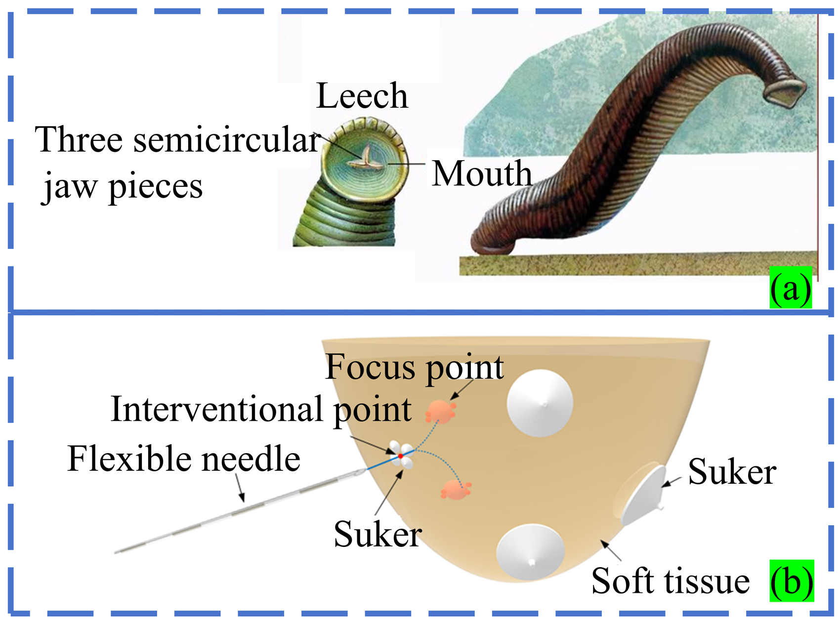
Biomimetic concept design of MR-guided mammary intervention robot based on the leech bloodsucking process.
There are a wide variety of animals, plants and substances in the biological world. In the long process of evolution, they have gradually acquired the ability to adapt to changes in nature in order to survive and develop. Therefore, we believe that the biomimetic design of MR-guided breast interventional robot based on the blood-sucking process of leeches has important clinical application potential. We hope that in the future, this robot can significantly improve the accuracy and efficiency of interventional surgery, while reducing patient trauma and recovery time. Strive to be widely used in future clinical practice to benefit more patients.
Footnotes
Declaration of conflicting interests
The authors declared no potential conflicts of interest with respect to the research, authorship, and/or publication of this article.
Funding
The authors disclosed receipt of the following financial support for the research, authorship, and/or publication of this article: This work was supported in part by Open Fund for the Key Laboratory of Advanced Processing Technology and Intelligent Manufacturing in Heilongjiang Province under Grant KFKT202204, in part by the National Natural Science Foundation of China (Grant No. 52275015), and the Regional Joint Fund of the National Natural Science Foundation of China (Grant No. U23A20391).