
Abstract
Overhead distribution lines are widely distributed and the environment is complex. At present, most of the overhead distribution lines in urban–rural fringe and rural areas are bare lines. These lines are susceptible to contact with tree barriers, airborne objects, and construction machinery, resulting in safety problems, such as tripping accidents and casualties caused by electric shock. In order to solve the hidden safety problems of bare lines, an insulation skin-wrapping robot for the overhead bare lines is designed and proposed innovatively in this paper. The mechanical system and the control system of the robot are designed and analyzed in detail. In order to detect whether the insulation skin is wrapped successfully, the robot uses machine vision technology to automatically detect the wrapping effect. In the experiments and engineering applications, the proposed robot is applied to the experimental line and 10 kV overhead distribution line. The results demonstrate the feasibility and practicability of the robot in insulation skin wrapping.
Introduction
Overhead power distribution line plays an important role in power transmission. In wind and rain conditions, grounding faults often happen in distribution lines. Presently, in order to solve the insulation problem of overhead distribution lines, the traditional solution is to replace the bare lines with insulated lines, as shown in Figure 1(a). Replacing bare lines with insulated lines incurs high construction costs and requires prolonged power interruptions,1,2 which reduces the reliability of the power supply and affects the production and living power consumption of users. In addition to the aforementioned method, an alternative effective solution is to wrap insulation skin (as shown in Figure 1(b)) on the bare lines in the running distribution lines, as shown in Figure 1(c). The construction period and investment of this method are greatly reduced. However, this method is inefficient, dangerous in construction, and needs to be cut off in the process of work, which also affects the normal transmission of power.
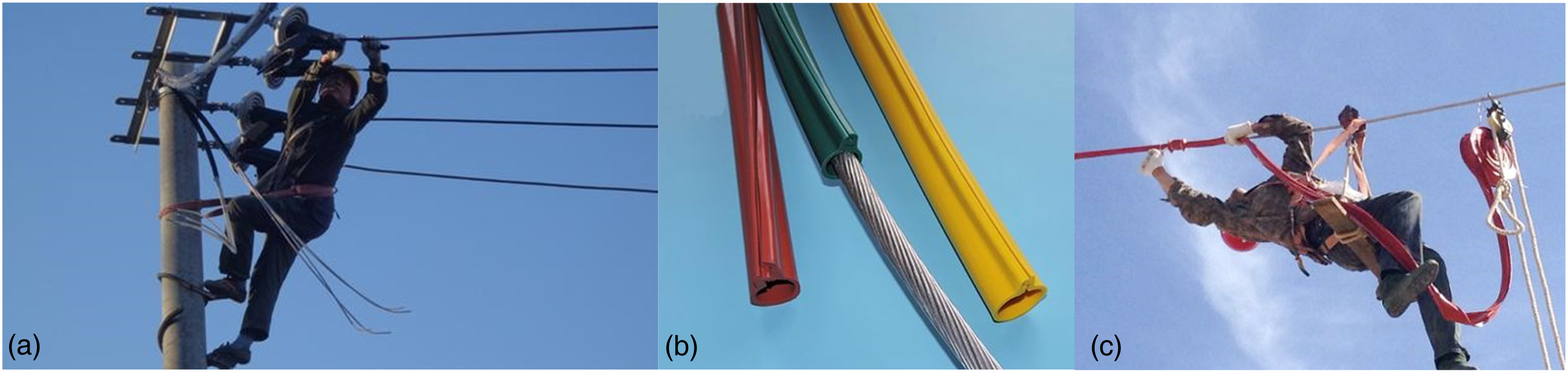
Appearance of insulation transformation method of the running overhead distribution line. (a) Replace the bare lines with the insulated lines; (b) insulation skin; (c) insulation skin manually wrapping. 13
Based on the statistics of power construction personnel casualties as shown in Figure 2, it can be seen that manual methods of work involve the risk of falling from height and electrocution. There is an urgent need to use automatic machinery to insulate overhead bare conductors.

Statistical data of human injury or death accident in power industry from 2012 to 2016 in China.
Line inspection robot is the earliest intelligent power transmission line robot. In 1991, Tokyo Electric Power Company developed the first inspection robot of overhead transmission line. 3 In 2003, a transmission line inspection robot, LineROVer, was developed by Quebec Hydropower Research Institute in Canada. 4 The first-generation robot can only remove the icing. With continuous improvement, it has become a multi-functional power robot, such as patrol inspection, maintenance, and obstacle clearing.5–7 Except for the inspection robot, the power maintenance robots are also studied by researchers. In 2020, a maintenance robot was proposed for insulator string replacement, spacer replacement, damper, and drainage plate maintenance. 8
Up to now, although some robots related to power systems have been proposed, robotic technologies are highly dependent on the nature of the tasks to be performed.9–11 For the insulation repair of overhead distribution lines, in 2016, Wu et al. developed an insulated automatic wrapping device for distribution lines. 12 The proposed robot can apply new insulating skin to the damaged insulating conductor, thereby completing the line repair. However, the robot can only repair a small section of bare lines, and can not complete the insulation transformation of long lines. In 2018, Hadi Kalani designed a new prototype robot for insulation of high voltage transmission. 13 Although the robot's structure is simple, the reliability of wrapping it with electrical tape is insufficient. In 2023, Wang et al. developed a series of miniaturization devices for insulation wrapping of distribution lines. 14 In 2024, Yang et al. developed an overhead ground wire repair robot. 15 However, the robot can only bundle the ground wire and can not solve the hidden safety problems of bare lines.
Traditional manual inspection methods for transmission lines can no longer meet the demand for high quality and reliability in grid maintenance. 16 Using a visual approach can be an effective solution to this problem. Li et al. propose a robot design for effective detection and recognition of obstacles through vision methods. 17 In 2023, Tang et al. proposed a high-voltage transmission line target localization algorithm based on line stereo matching. 18 Wang et al. proposed a method for detecting foreign objects and power component defects in high-voltage transmission lines based on the improved YOLOv5 algorithm. 19
To address the challenges associated with overhead bare wires, mitigate risks in manual transformation processes, and overcome the limitations of existing machines, this paper makes the following contributions. First, an insulation wrapping robot for overhead distribution lines is designed and proposed, and the mechanical structure of the robot is designed. According to the field situation of transmission lines and the characteristics of insulation skin for winding, a set of mechanical mechanisms are designed to cooperate with each other to complete the winding of conductors. Second, machine vision technology is used to automatically detect the package effect. Third, the reliability of the robot is verified by the package experiment in the laboratory and the running distribution line. Field experiments show that the robot can effectively wrap the overhead bare wire and realize automatic operation and live operation.
System composition of insulation wrapping robot
Mechanical system
The mechanical system is the carrier for the robot to complete the insulation wrapping function, which should have the following functions: (a) it can walk along the line in two directions, and in order to provide enough driving force, the mechanical system selects two driving wheels; (b) through the design of a variety of mechanical structures, the insulating skin can be wrapped on the distribution line; (c) after the insulation skin is wrapped, the surplus part of the insulation skin can be cut to adapt to different lengths of lines.
Control system
The robot control system consists of a ground controller and an upper computer control system, which communicate with each other by 2.4 GHz RF transceiver, receiver module. The upper computer control system of the robot is composed of the core single-chip microcomputer (STM32F4), motor driver, and current governor.
Power supply system
The robot power supply system provides power for all parts of the robot, which is mainly composed of the lithium-ion battery, direct current to direct current (DC–DC) Buck module, and low dropout linear regulator (LDO).
Sensor detection system
The sensing system consists of an inertial navigation unit, a visible light camera, a photoelectric sensor, a proximity switch, and an ultrasonic sensor.
Electromagnetic shielding box
The shielding box, the robot body, and the transmission line together constitute the equipotential body, which provides the feasibility for the wrapping operation without turning off the electricity. The shielding box is used to surround the development board, driver, and other hardware of the robot to prevent them from being interfered with by the external electromagnetic field.
Mechanical system design
Overall structure
The insulated robot mechanical structure diagram is shown in Figure 3. The main body of the robot is a frame structure. A feeding mechanism and walking wheels are installed on the frame. An opening for cable entry is designed at the bottom of the frame. The lifting mechanism is fixed on the cross beam at the bottom of the frame. The fastening mechanism is installed on the lifting mechanism and is located between the two walking wheels of the walking mechanism. The feeding and supporting mechanisms are installed on the longitudinal beam between the front wheel and the fastening mechanism.

Overall mechanical structure of insulated wrapping robot.
Walking mechanism
The robot has two driving wheels, and the structure of the walking wheel is shown in Figure 4. The walking wheel is driven by a brushless DC motor. The output shaft of the motor is connected with the hole of the rotating shaft through a fastening screw. The other end of the rotating shaft is installed on the edge bearing, and the other side of the bearing is fixed by a clip spring. In order to avoid slipping between the shaft and the walking wheel, the cross-section of the shaft is designed to be square. The walking wheels are designed as V-shaped wheels to improve adaptability and are made up of PVC material to reduce weight.
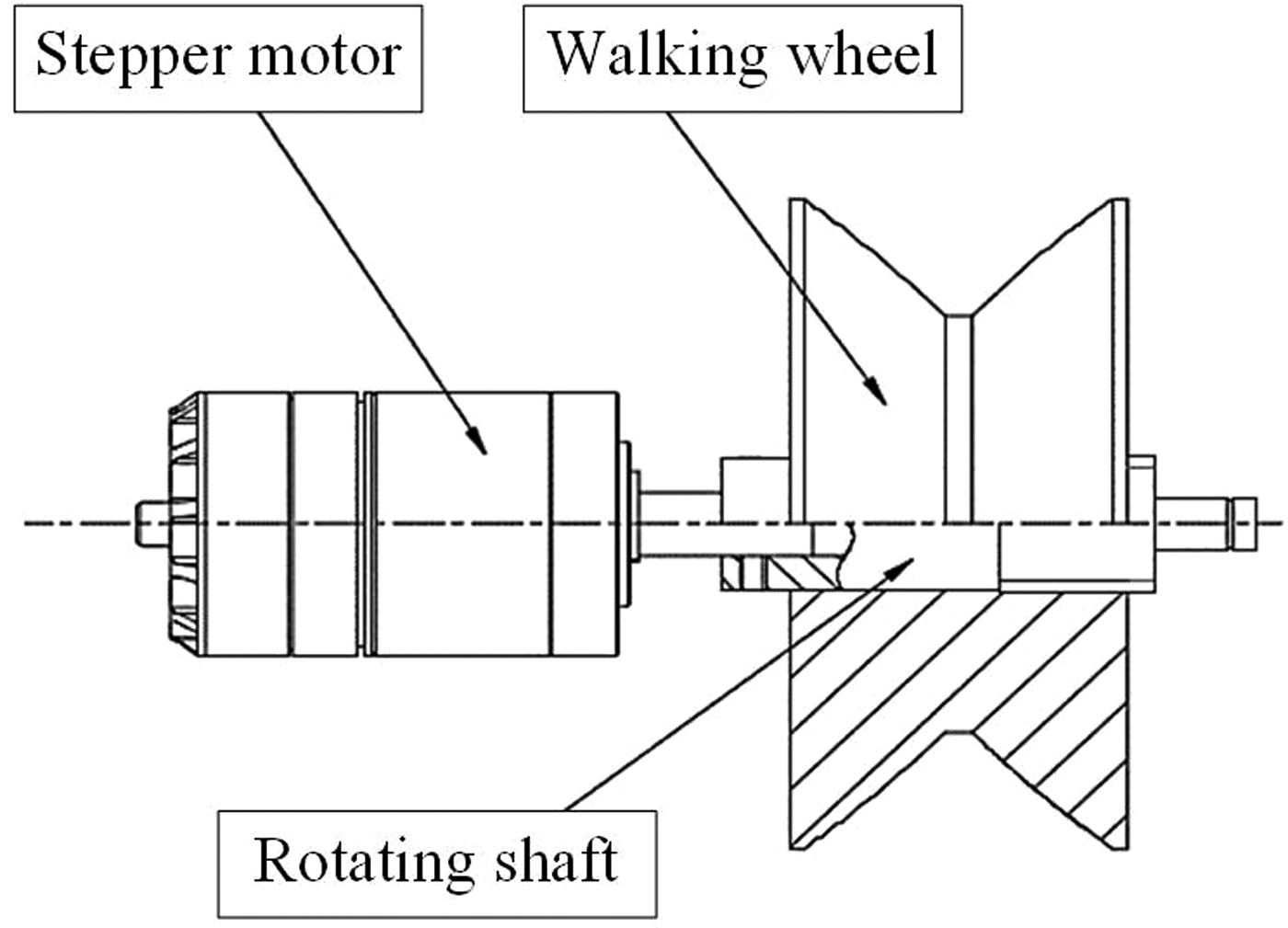
Schematic diagram of walking mechanism.
When the insulated wrapping robot walks on the lines, the walking wheel does not contact the wire directly. The walking wheels are pressed on the insulating skin, which wraps the bare wire. In order to make the robot have enough traction and braking forces when it goes up and down on the distribution line, it is necessary to have enough friction between the wheels and the insulating skin. At the same time, sufficient friction is also needed between the insulation skin and the wire to prevent slippage between the insulation skin and the wire. The gravity of the robot makes the traverse between the two wheels approximates a straight line. The designed maximum climbing angle of the robot is 15°, and the force analysis diagram of the robot walking is shown in Figure 5.

The force analysis sketch of robot walking.
From Figure 5,


It is assumed that the travel mechanism reaches a predetermined robot travel speed v (5 m/min, as shown in Table 1) after 1 s of uniform acceleration. The corresponding acceleration can be calculated as follows:

Technical indicators.

where G represents the gravitational force acting on the robot;
The external force F that can be applied is 0.0083 G, so the friction coefficient between the insulation sheath and the walking wheel of the proposed robot needs to be greater than 0.2783, still meeting the friction coefficient between the insulation skin and the wire, as well as between the insulation skin and walking wheel. In conclusion, even when subjected to inertial forces during acceleration and deceleration phases, the robot can maintain sufficient friction to prevent relative sliding between the contact surfaces.
From the above analysis, it can be seen that when the dynamic friction coefficient between the insulating skin and the walking wheel of the insulated wrapping robot is greater than 0.27, the robot has enough traction and braking force when it goes up and down. In order to enhance the climbing ability of the robot, a layer of silicone rubber materials is added on the surface of the walking wheels to increase the friction between the walking wheels and the insulating skin. The insulating skin is also made of silicone rubber. The friction coefficient between the insulating skin of the silicone rubber material and the walking wheel is 0.52, and the friction coefficient between the insulating skin and the wire is 0.59.
Even if the robot is subjected to inertia during start stop, it can still ensure that there is no relative sliding between the contact surfaces. Therefore, the friction between the insulation skin and the wire is greater than the friction between the insulation skin and the walking wheel, which ensures the relative static between the insulation skin and the wire. The robot meets the climbing requirements.
Feeding mechanism
The schematic diagram of feeding mechanism and working section is shown in Figure 6. The active and driven feeding wheels rotate reversely through the gear and flatten the insulation skin by the static friction of two wheels to realize continuous feeding. The output power of the motor is transmitted to the active feeding wheel through the synchronous belt.
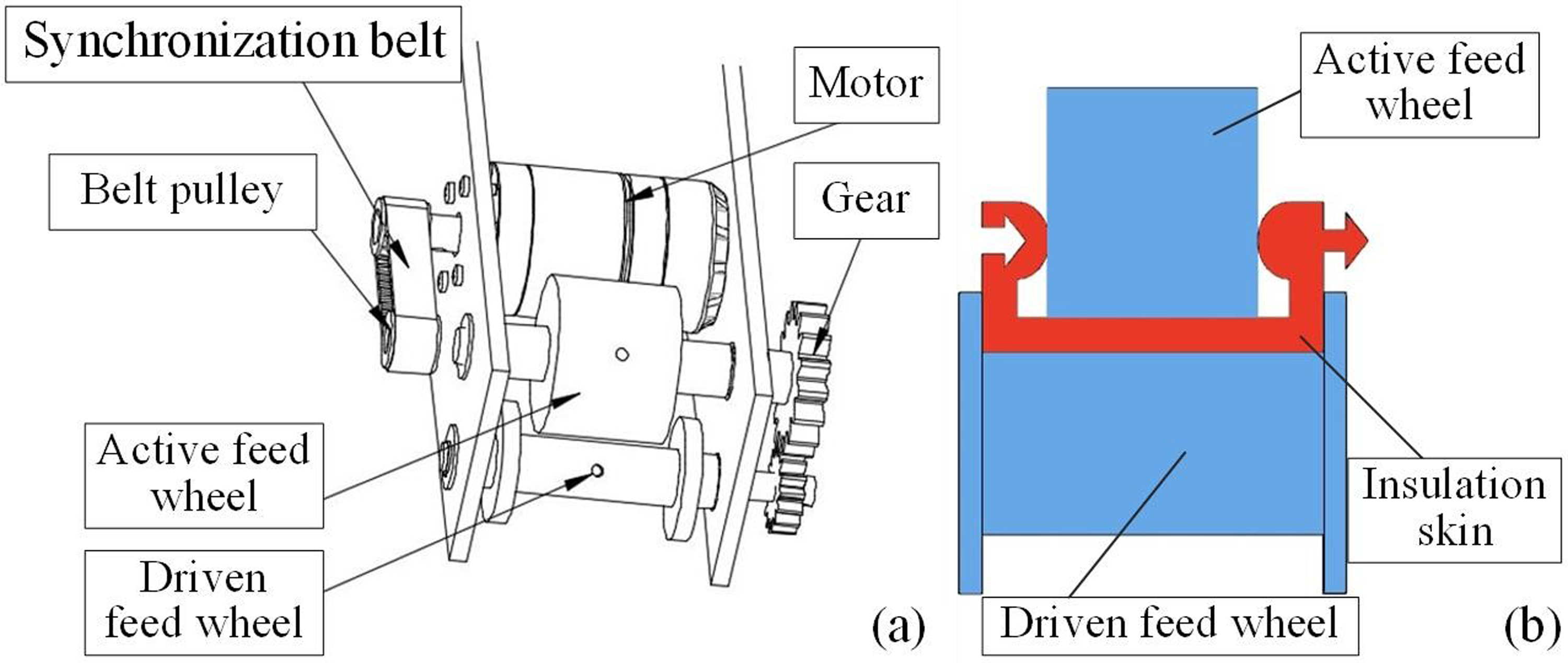
Schematic diagram of feeding mechanism.
The feed of the insulation sheath of the feeding mechanism mainly depends on the friction between the feeding wheel and the insulation sheath. The friction force needs to be greater than the transmission resistance. The resistance can be divided into two sections. The first part of the L1 section is the gravity of the insulation sheath of the inlet section of the feeding guide mechanism from the material box to the top of the robot. The length of this section of the sheath is about 1.1 m. The second part of the L2 section is from the guide mechanism to the inlet section of the feeding mechanism, about the friction resistance of the 0.7 m length of the sheath. The calculation formula for transmission resistance is
In the process of feeding, the upper and lower surfaces of the insulating sheath are subjected to the friction force of the feeding wheel. Then

Mechanical analysis model of feeding mechanism.
In order to ensure the successful completion of the feed, the pressure is set to 15 N and applied vertically to the active feeding wheel. The grid division diagram of the feeding mechanism, the total deformation diagram, the equivalent stress diagram of the insulation sheath, and the equivalent strain analysis results of the feeding wheel are shown in Figure 8(a)–(d).

Mechanical analysis model of feeding mechanism.
It can be seen from Figure 8(b) that the maximum displacement of the insulation sheath is 0.155 mm, and the overall displacement of the driving wheel is about 0.14 mm. The thickness of the insulation sheath is 2.5 mm, so the distance between the active feeding wheel and the driven feeding wheel is designed to be 2.35 mm, which is 0.15 mm smaller than the thickness of the insulation sheath. At this time, the pressure on the insulation sheath is about 15 N, which meets the feeding requirements.
Supporting mechanism
The insulating skin is a flexible material, so the designed support mechanism should be able to limit its displacement and control the shape change of the insulating skin. The supporting mechanism is composed of a steering engine, a coupling, two gears, and a clamping claw, as shown in Figure 9. Before the robot works online, the insulating skin is placed in the slot of the clamping claw. The distribution line enters through the gap of the clamping claw. The clamping claw is driven by the steering gear to close so that the insulating skin is ready for wrapping.

Schematic diagram of feeding support mechanism.
Fastening mechanism
Figure 10 shows the structural diagram of the insulating skin fastening mechanism. The insulating skin in the open state changes into the buckle state after passing through the buckle mechanism. The clamping mechanism has two rows of symmetrically distributed clamping wheels, each driven by a motor. The two rows of clamping wheels rotate reversely and are connected with the rotating shaft of the clamping wheel through a coupling. The concave area of the clamping wheel is the main area in contact with the insulation sheath buckle. In order to ensure the motion coordination between the clamping wheel and the walking wheel during the robot walking, the linear speed at the minimum diameter of the clamping wheel is equal to the walking speed of the robot by controlling the motor speed of the clamping wheel and the walking wheel of the robot. In the design of the robot motor, we calculate the motor speed by the diameter and linear speed of the clamping wheel and the fastening wheel respectively.

Schematic diagram of fastening mechanism.
In order to ensure that the insulating skin will not fall off from the buckle during the clamping process and can be correctly buckled, the clamp of the clamping wheel is matched with the shape of the insulating skin, as shown in the Figure 10.
Lifting mechanism
In order to leave a gap for the installation of the robot, the lifting platform is at the bottom. After the robot is installed on the line, the lifting platform is lifted to make the upper support plate of the fastening mechanism and the bottom end of the insulating skin in the clamping claw at the same height. The insulating skin can enter the fastening mechanism to realize wrapping (Figure 11).

Schematic diagram of lifting mechanism.
Shearing mechanism
In order to make the robot flexible for different lengths of power distribution lines, the insulation skin can be cut when the robot runs to the planned wrapping section of the line. The shear structure is shown in Figure 12. In order to realize the round-trip cutting action of the cutting tool, the mechanism uses DC motor as the driving element and crank connecting rod as the transmission mode. In order to make the tool move more smoothly, both ends of the tool are installed on the linear bearing, which is matched with the linear slide rail. The slide rail is fixed on the base.
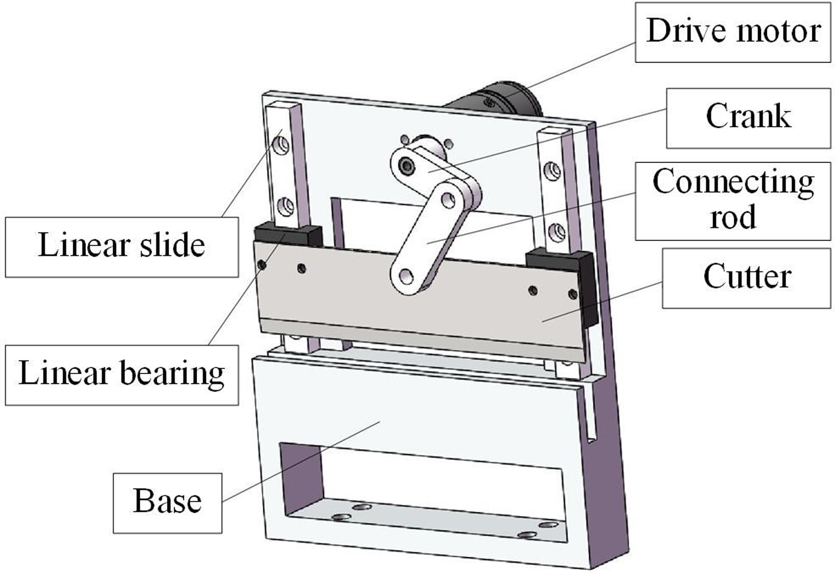
Schematic diagram of shearing mechanism.
When the feeding mechanism and walking mechanism are working, the falling of the cutting blade will hinder the robot's walking, leading to motor blockage or mechanism damage. The installation position of the proximity switch is shown in Figure 13. To prevent interference between the insulation skin and the cutter, a normally closed proximity switch is installed on the side of the cutter bracket to detect the position of the cutter. When the cutting blade is pushed out, the proximity switch will output a signal to the main controller, which will output a brake signal to the feeding mechanism and walking mechanism motors, and shield the control signals of the feeding mechanism and walking mechanism. When the cutting blade returns to its original position, the proximity switch remains normally closed and the remote control resumes control of the feeding mechanism and walking mechanism.

Schematic diagram of proximity switch.
Storage box
The storage box is used to store the insulating skin used for the wrapping. The cross-section of the storage box is designed as a parallelogram so that the insulating skin can smoothly bypass the distribution network line, while the center of gravity is kept on the symmetrical plane of the robot. The side plates of the storage box have been processed with two rows of through-holes, which can reduce the weight, play the role of ventilation, reduce the influence of crosswind on the robot, and can clearly see the residual amount of insulating skin in the material box (Figure 14).

Schematic diagram of storage box.
Insulation wrapping process
As shown in Figure 15, the working process of the insulation wrapping robot is divided into three stages: preparation stage (Figure 15(a) and (b)), wrapping stage (Figure 15(c)–(e)) and end stage (Figure 15(f)).

Workflow of insulation wrapping robot.
Preparation stage: Figure 15(a) shows the preparatory state of the robot before it wraps online. The insulating skin is loaded in the storage box. At the same time, the insulating skin is introduced into the feeding mechanism through the guiding mechanism on the top of the frame and then stuck into the supporting mechanism through the walking mechanism (Left subfigure of Figure 15(a)). The clamping claw of the supporting mechanism is opened. In order to leave space for the robot to wrap online, the lifting mechanism is located at the bottom (right subfigure of Figure 15(a)). Figure 15(b) shows the process of the robot wrapping online. The construction workers use the insulated support rod to install the robot on the power distribution line (left subfigure of Figure 15(b)). The two wheel frames of the robot's walking mechanism are on the distribution line.
Wrapping stage: When the robot starts to wrap, as shown in Figure 15(c), the clamping claw of the feeding support mechanism is closed by the remote control system (left subfigure of Figure 15(c)), and the lifting mechanism rises to the appropriate position (right subfigure of Figure 15(c)). Figure 15(d) shows the process of the robot wrapping the insulating skin. The walking mechanism, feeding mechanism and fastening mechanism are started at the same time. When the robot moves forward, the insulating skin is fed continuously, and the insulating skin is clamped after passing through the fastening mechanism (right subfigure of Figure 15(d)). Therefore, the robot can wrap the insulation around the distribution line. Figure 15(e) shows the end of the insulation modification process. When the package is finished, the driving parts of each mechanism of the robot stop and the cutting mechanism runs to cut the insulating skin (left subfigure of Figure 15(e)). After that, the cutting mechanism stops. The walking mechanism, feeding mechanism, and buckle mechanism continue to operate, and then wrap the remaining insulating skin on the distribution line (right subfigure of Figure 15(e)).
End stage: The robot continues to run and completely wraps the excess insulation skin around the distribution line. The insulating skin leaves the fastening mechanism, and then the insulating package ends (right subfigure of Figure 15(f)). Then, the clamping claw of the supporting mechanism is opened, and the lifting mechanism is lowered at the same time. Finally, the robot is removed from the distribution line, and the wrapping work is finished.
Control system design
Hardware composition and function of control system
The hardware of the robot control system is composed of an embedded control center, a motion control unit, a sensing detection unit, a remote control and data transmission unit, and a power supply module, as shown in Figure 16.
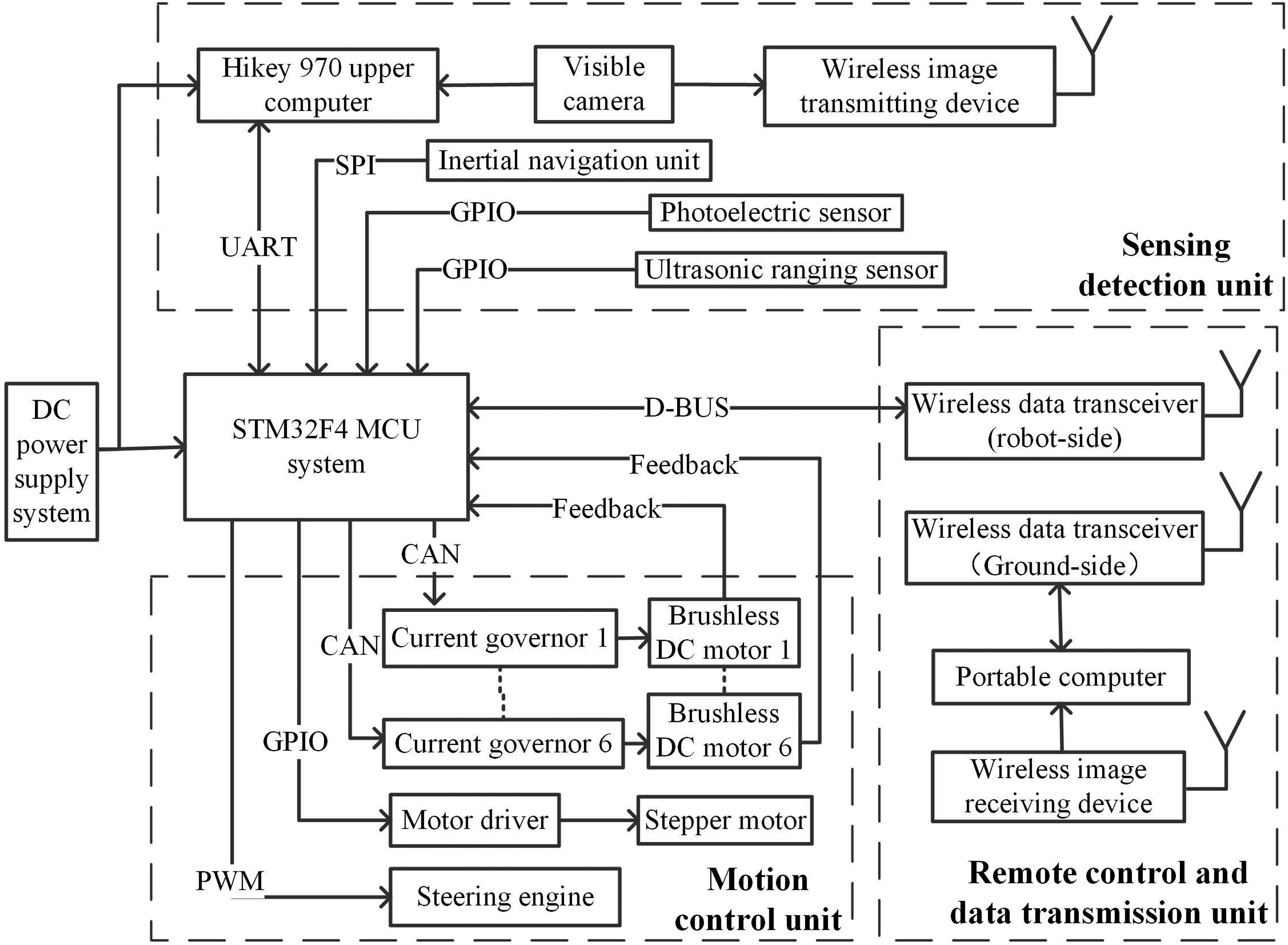
Block diagram of hardware composition and function of control system.
The embedded platform is selected for the robot motion control system, and the control chip is STM32F427. The data communication between STM32F427 and external devices mainly uses CAN, UART and SPI interfaces.
The motion control unit consists of six brushless DC reduction motors, a steering gear, and a stepper motor. Each DC motor is equipped with a current governor, and the stepper motor is equipped with a driver.
The sensing detection unit mainly includes vision detection system, inertial measurement sensor, ultrasonic sensor, and photoelectric sensor. This unit mainly collects the image information of the robot insulation wrapping effect and the body posture and position information.
The remote control and data transmission unit includes signal wireless transceiver modules and image wireless transmission modules. The power supply unit is composed of lithium-ion battery and step-down module.
Software design of control system
The software system of the insulation wrapping robot is the core of the control system. The motion control, data communication, and sensor data processing of the robot are all completed by the software system. Therefore, the software design of the robot needs to meet the requirements of stability and reliability. In this paper, The FreeRTOS real-time operating system is transplanted into the main controller of the insulation wrapping robot to schedule tasks.20,21 The software system structure of the insulation wrapping robot based on the FreeRTOS operating system is shown in Figure 17.

Software system structure diagram of insulation wrapping robot.
According to the work requirements, the tasks of the robot are divided into five levels according to priority, which are the highest priority tasks: system initialization tasks; higher priority tasks: motion control tasks; high-priority tasks: data transceiver/analysis tasks; general priority tasks: communication tasks with the ground console; low priority tasks: module offline monitoring tasks. Task scheduling is used to manage the tasks that the robot needs to complete. By defining the priority of the task, high-priority tasks are executed first. The task execution conflict is avoided, and the stability and reliability of the control system are improved.
Application of machine vision
The robot transmits the image information collected by the visible camera to the portable computer in real time, but manual inspection may affect the accuracy of inspection because of fatigue, lack of experience, and other factors. Therefore, the computer vision system is more reliable for the automatic identification of wrap results. Visual recognition can improve work efficiency and ensure the quality of the wrap.
In order to detect the quality of the insulation package, the fixed focus camera is used and installed under the distribution line. At the same time, the distance between the camera and the power distribution line remains unchanged. Determine whether the insulation skin is correctly bent through computer vision processing algorithms.
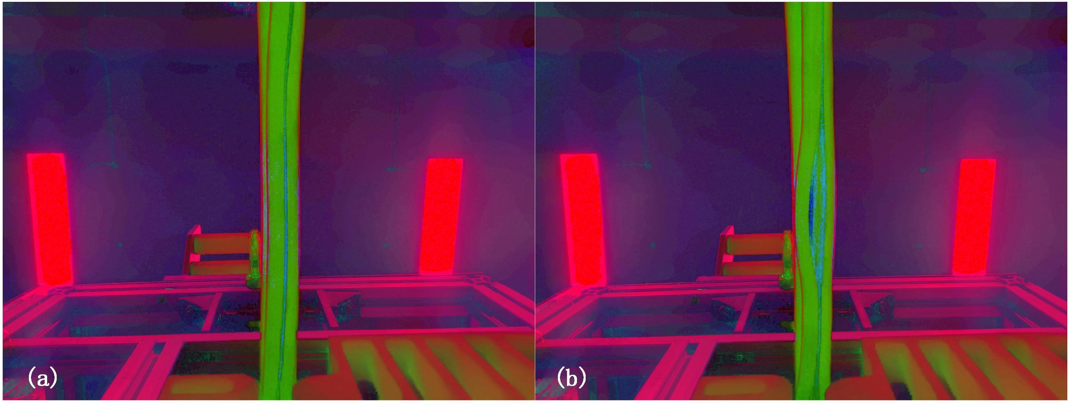
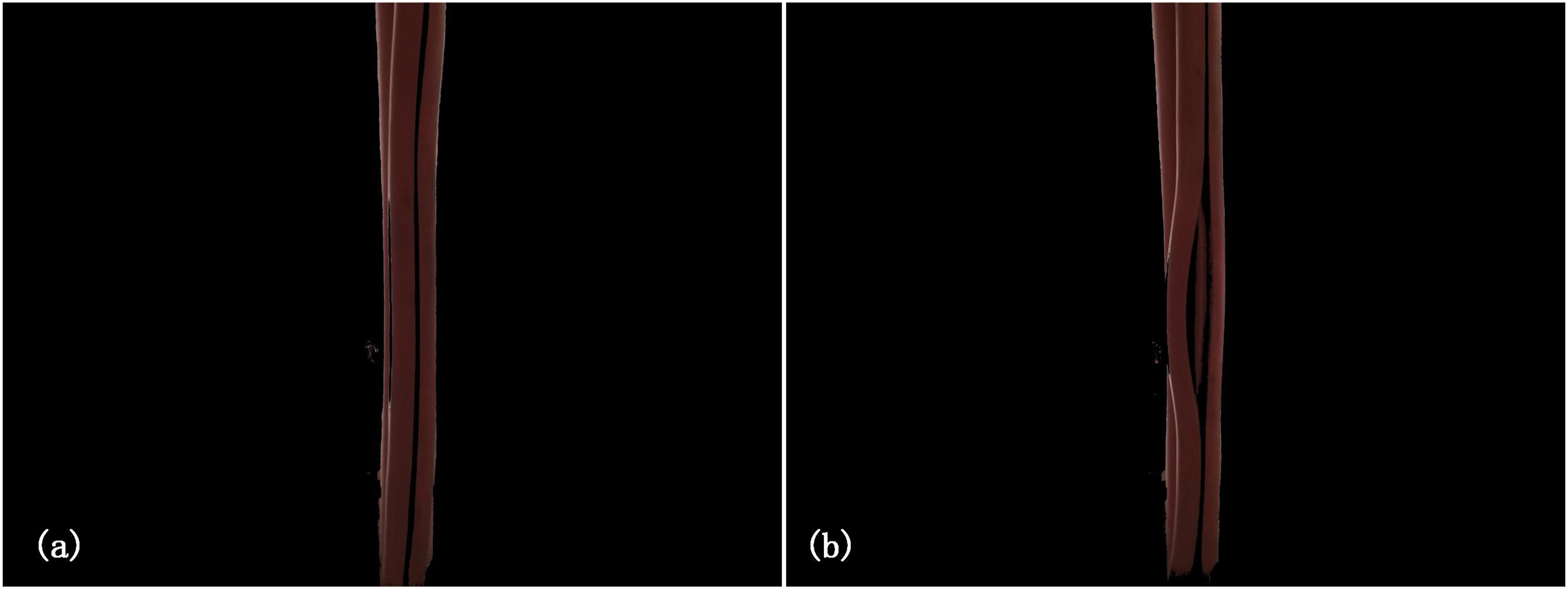
During the operation of the robot, the successful picture of the insulating skin wrapping is shown in Figure 18(a), and the picture of the failure of the insulating skin wrapping is shown in Figure 18(b). According to the characteristics of the collected image information and the detection purpose, the image processing process is shown in Figure 19.

(a) Image of successful insulation wrapping; (b) image of failed insulation wrapping.

Processing flow chart of robot vision system.
Image preprocessing
In order to reduce the influence of noise as much as possible, Gaussian filter is used in image preprocessing. The Gauss function is as follows,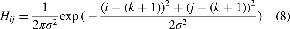
HSV color feature extraction
The most convenient method to extract the insulating skin features in the image is to separate the red area of the insulating skin. Therefore, this paper transforms the image from RGB color space to HSV color space.
22
The formula of transforming RGB color space into HSV color space is
Images transformed from RGB space to HSV space. (a) Successful insulation wrapping; (b) failed insulation wrapping.
Images after feature segmentation. (a) Successful insulation wrapping; (b) failed insulation wrapping.
Insulation skin wrapped detection algorithm
Using the YOLOv7 single-stage object detection model 24 to detect the results of insulation skin wrapping, the insulation skin feature segmentation image is used as the input image of the network, reducing the interference of irrelevant features on the target detection network and improving the convergence ability of the network. If the edge sheath wrapping is detected, have the robot reverse a certain distance and start wrapping again. Figure 22 shows the structure of the YOLOv7 object detection network.
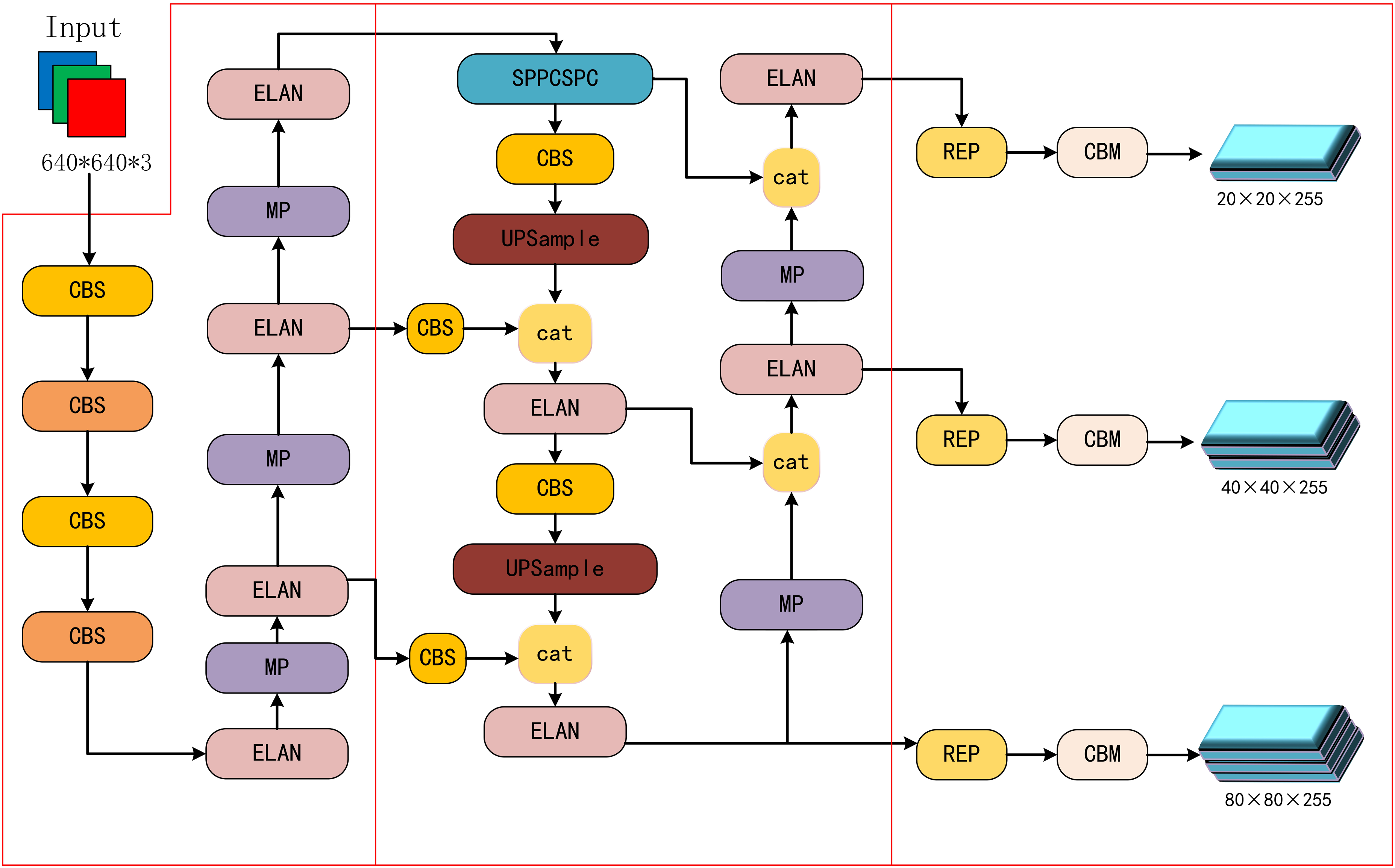
The structure of YOLOv7 object detection network.
An efficient ELAN module 25 was adopted in the Yolov7 detection model. By using a dense residual structure and expanding, transforming, and fusing cardinals, the learning ability of the original network is enhanced, avoiding the destruction of the stable state of the original gradient path caused by infinite superposition of computing units. By controlling the shortest and longest gradient paths and using feature map concatenation, the network can learn more features and have stronger robustness. Figure 23 shows the structure of the ELAN module.
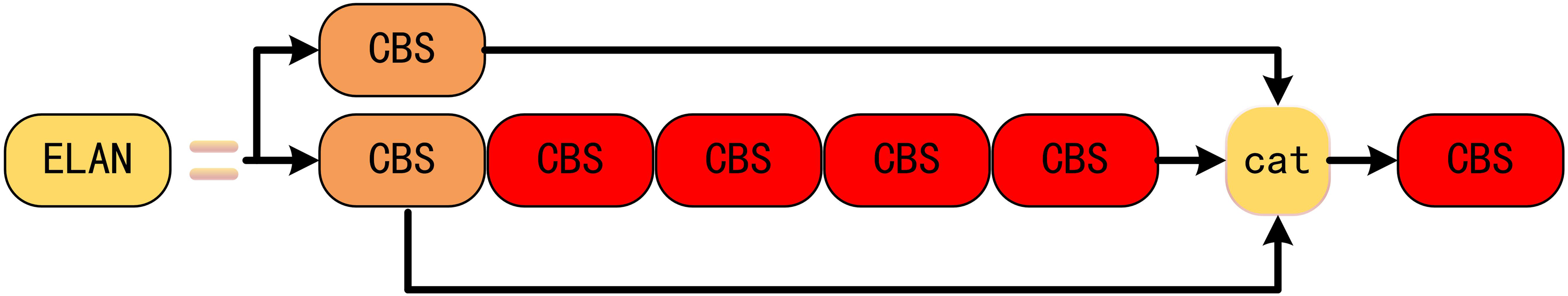
The structure of ELAN module.
The SPPCSPC module divides the features into two parts, one of which is subjected to conventional convolution processing, and the other is subjected to SPP structure 26 processing, using four different scales of maximum pooling with four receptive fields to distinguish between large and small targets. Finally, the two parts were concatenated into feature maps to reduce computational complexity while ensuring accuracy. Figure 24 shows the structure of the SPPCSPC module.
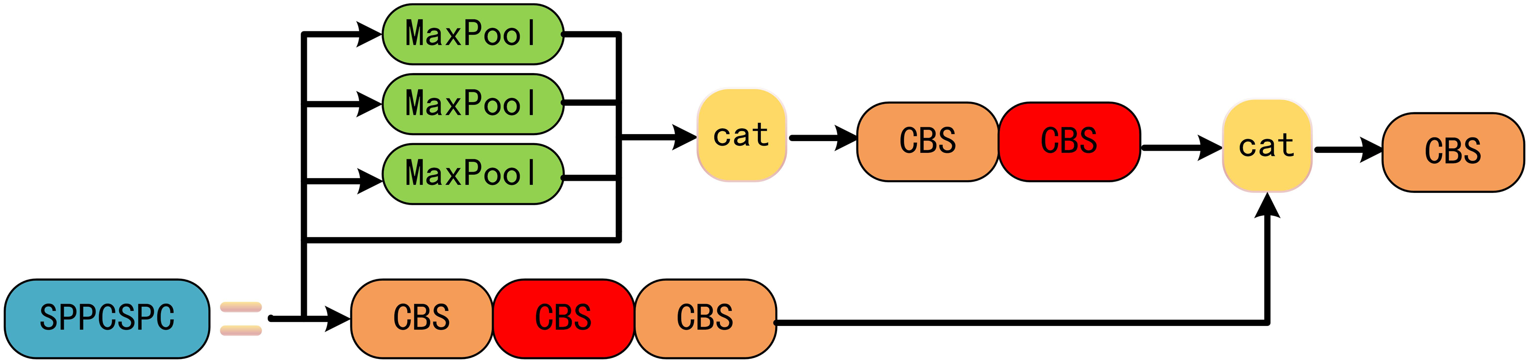
The structure of SPPCSPC module.
The MP module 27 uses two downsampling methods, namely maximum pooling and 1 × 1 convolution, to perform two branches separately. Finally, the two branches are concatenated for feature maps, avoiding the problem of feature loss caused by a single downsampling method. Figure 25 shows the structure of the MP module.

The structure of MP module.
During the dataset establishment phase, manual buckle closure was used to simulate the success or failure of the buckle as a training set image. The label box represents the opening of the insulation sheath. To improve the robustness of the training results, the dataset is subjected to data augmentation, random augmentation is performed in HSV space, and the original image is rotated, translated, and scaled. The training set images were preprocessed for feature segmentation, and the insulation sheath area in HSV space was preserved through masking to simulate the actual target detection of insulation sheath feature segmentation images. Figure 26 shows the original images of the training set and the actual training images after mask processing.

Training set image. (a) Original training set image; (b) training set images after mask operation.
During the training, 200 epochs were trained on 300 training set images, and the training loss results, accuracy, and recall obtained from the training are shown in Figure 27. For the accuracy of training, when the epoch was 197, the highest recall and precision were 0.97 and 0.96, respectively. By using insulation sheath feature segmentation images for training, interference information is removed, and the object features in the training set are clearer. Due to the use of masks in actual insulation sheath detection, only the insulation sheath area is retained, reducing interference information does not weaken the robustness of the network.

Training loss curve and evaluation index curve. (a) Rectangle box loss and confidence loss curve; (b) precise and recall curve.
The YOLOv7 training results using the masked dataset are shown in Figure 28, and the prediction box can fully contain the failed areas of insulation sheath wrapping.

YOLOv7 network prediction results. (a) Input image of object detection network; (b) detect results of insulation skin wrapping failure.
Image 28 shows the detection results of the YOLOv7 object detection network trained on a dataset of insulation skin wrapping conditions that filter irrelevant information. After filtering the training set and actual detection images through HSV color space, the network can capture the most effective features without being disturbed by other features in the scene. At the same time, this method significantly reduces the difficulty of creating datasets and has a certain reference value for training other network models.
Prototype and engineering application of robot
The main technical specifications of the insulated wrapping robot are summarized through prototype making and field test, as shown in Table 1.
The robot prototype is shown in Figure 29(a), and the pictures of the prototype operation in the test site are shown in Figure 29(b) and (c). The details of the insulation wrapping effect are shown in Figure 29(d). Aiming at the wrapping efficiency and climbing ability of the wrapping robot, a lot of experiments have been done on the simulated and actual lines. The experimental results show that the two-wheel driving mode provides enough driving force for the robot. The friction coefficient between the walking wheel and the insulating skin is 0.52, greater than 0.27, and the maximum climbing angle is 15 degrees higher than the design requirement. The driving wheel can adapt to different conditions with a V-shaped structure; insulating skin can be adapted to the fastening mechanism to realize the function of bare wire wrapping; the rotation speed of each motor keeps a certain linear relationship to realize the robot wrapping at a speed of 5 m/min; the center of gravity of the whole robot is arranged in the underneath suspended packing box, effectively avoiding the occurrence of overturning and disconnecting of the robot in the case of strong wind.

(a) Test site with simulated lines. (b) and (c) Pictures of prototype operation in the test site. (d) The effect of robot wrapping insulation skin.
The robot prototype is shown in Figure 30(a), and the starting installation position of the insulation wrapping experiment is shown in Figure 30(b). The proposed robot is applied to 10 kV overhead distribution line. The whole process of robot insulation wrapping is shown in Figure 30(c) and (d). Through the field engineering application results, the proposed robot can realize the insulation repair of overhead distribution lines.

(a) Photo of robot prototype. (b) The starting installation position of the insulation wrapping experiment. (c) and (d) Engineering application of robot in the running 10 kV distribution line.
Conclusion
In conclusion, this paper designs an insulation wrapping robot for the distribution lines, which breaks through the existing technology and proposes a new method of wrapping overhead wires. An insulation wrapping robot is a kind of robot running on high voltage wires, which can replace humans to complete the insulation transformation of bare distribution lines. First, the mechanical structure of the robot is designed. According to the field situation of the transmission line and the characteristics of the insulation skin used for wrapping, a set of mechanical mechanisms is designed to cooperate with each other to complete the wrapping of the wire. Second, machine vision technology is used to automatically detect the wrapping effect. Third, the wrapping experiments are conducted in the laboratory and the running distribution line. The field experiments show that the wrapping robot can significantly improve the efficiency and quality of insulation reconstruction, and effectively avoid power failure and personal injury.
Footnotes
Declaration of conflicting interests
The authors declared no potential conflicts of interest with respect to the research, authorship, and/or publication of this article.
Funding
The authors disclosed receipt of the following financial support for the research, authorship, and/or publication of this article: This work was supported by the National Natural Science Foundation of China (grant number 52175519, 61801402).