
Abstract
It is essential to efficiently perform collision detection for robotic manipulators obstacle-avoidance planning. Existing methods are excellent when manipulator links are simple and obstacles are convex. But they cannot keep the accuracy and the efficiency at the same time when manipulator links or obstacles are nonconvex. To decrease the computing time and keep a high accuracy, this article presents a collision detection method based on point clouds and stretched primitives (PCSP). In traditional methods, obstacles are often represented either by a convex body or enormous amounts of points. But this needs a trade-off between the accuracy and the computing time when obstacles are concave. In the proposed method, we represent obstacles and complex manipulator links as stretched geometric bodies while simple manipulator links are enclosed by capsules with different sizes. The stretched body is constructed by the original point cloud from sensors but it only requires a small number of points to approximate the original object. We conducted the simulation experiment in our specific scenarios, and the results indicated that PCSP required less computing time while maintaining a high level of accuracy compared to existing methods. We also conducted standard benchmark tests in general scenarios, which showed that PCSP had advantages over libraries based on bounding volume hierarchies when concave objects are close together. Finally, we implemented PCSP for a manipulator obstacle-avoidance motion planning in a real-world environment, which demonstrated that PCSP was effective.
Introduction
The growing use of robots equipped with manipulators is being proposed to improve industrial manufacturing, agricultural production, and daily life. Requirements for manipulator motion planning are becoming more and more stringent. Manipulator motion planning aims at a feasible path given a start position and a goal position.
1
That is often performed in its joint space,2–4 a configuration space (C-space). Each configuration clearly represents the pose of manipulator in its workspace. The dimensionality of the space matches the number of joints, which is also known as the manipulator's degrees of freedom (DOFs).
5
Given a configuration, it is only subject to either
Obstacle-avoidance motion planning has been one of the most major issues in the robotics field and numerous approaches have been proposed. In different robots, most of researches were focused on unmanned ground vehicles (UGVs),10,11 unmanned aerial vehicles (UAVs),12–17 and unmanned underwater vehicles (UUVs).18–20 For a UGV to operate in dynamic environments, Khan et.al
10
presented a proximal planning and control formulation approach. Each obstacle was represented by a circle with an estimated radius, and obstacle avoidance constraints were formulated by distance away from the center of an UAV. For multiple UGVs in a changing environment, Tran et.al
11
introduced a distributed virtual leader-follower formation control strategy and then generated a local steering force for UGVs to avoid obstacles, in which UGVs were treated as points and obstacles were discretized into grid cells. For UAVs in a multiobstacle environment, Huo et.al
14
proposed a collision-free model predictive control (MPC) algorithm. To guarantee the safety of UAVs and make the online optimization problem computationally tractable, they handled collision avoidance constraints using a plane to separate polyhedral approximations of obstacles trajectories from the UAV trajectory. For a large swarm of UAVs with coverage constraints in complex urban scenarios, Arul et.al
15
proposed an efficient collision avoidance method named as LSwarm. To reduce the computation burden and ensure scalability, they constructed a Look Up Table to select a collision avoidance velocity that maximized the conformity of an agent to an optimal path. LSwarm was also applied into comparison of different building avoidance strategies to solve the multiagent urban dynamic coverage problem.
16
For multiple UAVs tracking a single ground target in high-rise buildings areas, Kim et.al
17
presented an optimal algorithm considering collision avoidance and target tracking, which prevented collisions by adding additional acceleration commands that maximized distances of UAVs. For a biomimetic underwater vehicle in dynamic environments, Lv et.al
18
designed a fuzzy artificial potential field method with a velocity component to ensure obstacle avoidance. Based on the position and velocity of the underwater vehicle and a circle obstacle, the method planned a path through the moving circle obstacle without collision. For multiple AUVs cooperative motion planning, Hadi et.al
20
presented a decentralized deep reinforcement learning algorithm that directly mapped end-to-end sensing data to the desired collision-free speed and steering commands. It is convenient for these above robots to perform collision detection in motion planning. (1) The robot is regarded as a point and position information of obstacles are explicit in C-space. In this case, it is determined directly whether the robot overlaps with its surrounding obstacles. (2) The robot is represented by a convex geometric body while obstacles are enveloped by other convex geometric bodies. In this case, it is enough to perform collision detection based on typical bounding box methods. However, there are disadvantages when these two methods are employed into manipulator motion planning. Although the whole manipulator can be considered as one point in the C-space, it is commonly hard to separate
Many schemes have been proposed to guarantee the manipulator obstacle avoidance. A general method is on the basis of “artificial force field” proposed firstly by Khatib.
21
By this method, obstacles are described as repulsive poles and the goal position is described as the attractive pole. Then, obstacle avoidance planning is incorporated into an optimization problem.22,23 However, it is mainly employed in manipulator executing but not in motion planning. Saha et.al
24
proposed a small-step retraction method to help probabilistic roadmap (PRM) planners find paths through narrow passages for industrial robots aiming at welding or painting. The method implicitly constructed a fattened free space by thinning the geometric models of objects based on the Medial-Axis Transform technique, in which the new planner was faster than the pre-existing PRM planner. However, the medial-axis approximation to thin object was treated as a precomputation step, which was computationally expensive. For robotic machining of a wind blade, a fast global collision detection method was presented based on Feature-Point-Set and bounding volumes.
25
However, it was specially designed for large curved components, and offline programming technology was necessary to establish the Feature-Point-Set of the machining area. For robots with planar manipulators, it is widespread to make obstacles or other robots orthogonally project onto
In brief, many obstacles-avoidance schemes are designed for manipulator motion planning. However, there exists inadequacy for these studies. In these studies, either obstacle model is too coarse to reduce computational burden or the topic of collision detection is not discussed completely. These actually influence the performance of manipulator obstacles-avoidance motion planning.
It is the geometry intersection judgement that plays an irreplaceable role in collision detection. The most common geometric body is the bounding volume containing the bounding sphere (BS),32–34 the aligned axis bounding box (AABB),32,33,35 the oriented bounding box (OBB),32,33,36 and the discrete orientation polytope (k-DOP).32,33,37 It is fast for them to perform collision detection. However, they are limited the simple environment and regular objects. Method directly using the point cloud from sensors is suitable for every scenario and can have quite high accuracy. 38 But it is at the cost of a significant amount of computing time. Extra efforts have to be made in a trade-off between computing time and the number of points. 39 Gilbert–Johnson–Keerthi (GJK) method is widely implemented in geometry intersection judgment, 40 and several improvements have been made.41–43 But it is mainly used to perform intersection judgment or calculate the minimum distance among convex geometries.7,26 In addition, one pseudodistance calculation method based on convex plane polygons (CPPs) 44 was also proposed for manipulator motion planning. In the method, obstacles are represented by numerous polygons and manipulator links are described by cylinders with different sizes. CPPs method is suitable for concave polytopes and can reach a high accuracy. However, it will take much time when the polytope has lots of faces or the link has a complex shape.
To decrease the computing time and keep a high accuracy, this article presents a collision detection method based on point clouds and stretched primitives (PCSP). PCSP treats obstacles as stretched geometric bodies based on the sampled point cloud or the known three-dimensional mesh model. Simple manipulator links are represented by capsules with different sizes while complex manipulator links are treated as stretched bodies. In this case, PCSP represents concave objects or curved objects with a higher precision than the typical bounding box and has less points than the original point cloud.
In the following, the second section elaborates the proposed method, containing objects representation and detection algorithms. Simulation experiments are performed in the third section, in which two accuracy indexes and the computing time of PCSP are evaluated. In the fourth section, PCSP method is implemented for a manipulator in a real-world overhead-line scenario, which demonstrates PCSP is an effective collision detection method for manipulator obstacle-avoidance motion planning. At last, the fifth section presents the final conclusion.
Method
Objects representation
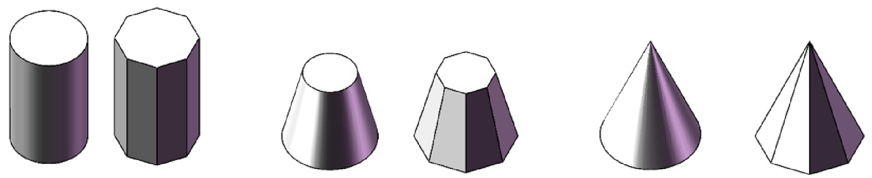
It is important for collision detection to represent objects with an appropriate shape. The stretched body is selected considering shapes of most objects in products manufacturing, industrial maintenance, and daily life. Carefully observing the surroundings, the stretched body can be employed for desks, workbenches, shelves, computers, and trash can. As illustrated in Figure 1, the stretched body has a high degree of approximation. The manipulator was usually described by cylinders.7,29,44–47 But for most manipulators, links are connected by rotational joints. When the link is rotated, the end sweeps a surface. It is more intuitively reasonable for manipulator collision detection to model the link using the capsule. With the capsule, some invalid path may also be avoided in manipulator motion planning. When an obstacle intersects with the surface, the path between the near configuration and the sampled configuration may be invalid. If so, it occurs for the cylinder model that plenty of time has been consumed when the collision configuration was detected. Furthermore, the capsule is simple in structure, where it is only a geometry body swept by a sphere along a line segment. During geometry intersection testing, it is convenient than the cylinder to process the capsule end shape. Hence, it is better to approximate a simple manipulator link using the capsule than using the cylinder. Except for simple links, we also consider links with complex shape and the end effector. As illustrated in Figure 2, stretched geometric bodies are generated with known 3D model of manipulators. Based on the above, the collision detection between a manipulator and obstacles is converted to the spatial relationship between capsules and stretched geometric bodies.

Objects representation with stretched geometric bodies.

Manipulator representation with capsules and stretched geometric bodies.
Construction of a stretched geometric body from the point cloud contains the direction selection and the primitive extraction. It is easy to construct the stretched geometric body if the best direction is given. More generally, we select the best direction from three principal orientations. Principal component analysis (PCA) is a statistical technique that allows us to analyze the distribution of points and to identify its main axes of variation. By applying PCA to the point cloud, we can calculate the eigenvectors and eigenvalues of the covariance matrix. By analyzing the eigenvectors obtained from PCA, we can determine the principal orientations of the object in 3D space. As illustrated in Figure 3, we got projections in three principal orientations based on PCA and then the best direction was determined by the least volume.

Construction of the stretched geometric body for a bunny.
To extract the stretched primitive, we project the original point cloud into a plane and process it as a binary image Find the top-left foreground pixel, mark it as Starting from Set Let Set Repeat steps (5) and (6) until

Contour extraction of a binary image.
Thirdly, we select the stretched orientation where the estimated volume is the smallest. We use the following area formulation to estimate the volume of a stretched body, which is derived based on the Green's theorem.
Collision detection algorithms
We use capsules to represent simple manipulator links while generate stretched geometric bodies from the original point cloud. The collision detection between capsules and stretched bodies is mainly divided into three stages. As illustrated in Figure 5, we selected a general stretched body to describe the collision detection. (1) If the capsule is completely located away from the side of obstacle along the stretched direction in Figure 5(a), return no collision. If it is illustrated as Figure 5(b), go into the second stage. (2) In the stretched direction, analyze the projection profile of geometry body that is a sheared capsule by two end faces of the stretched body. (3) On the projection plane, if there exists overlap area between the sheared capsule profile and the end face profile, return collision. If not, return no collision. Details for every stage are the followings (Figure 6).

The capsule representing a manipulator link and the stretched geometric body representing an obstacle. (a) The 3D view and (b) the side view.

Two position relationships between the capsule and the stretched geometric body. (a) Absolutely no collision and (b) uncertain collision state.
We use the radius r and the axis line

We formulate two end planes of the stretched obstacle as:


Combined with the above three equations, we get the intersection points of the line


Projection profiles of a capsule body sheared by two parallel planes.


The projection profile is composed of circular arcs, elliptical arcs, or segments. As illustrated in Figure 8, The profile of capsule body, named

A projection profile and a stretched geometric primitive in the projection plane.
For the curved parts of

We sample the arc from


We use the stretched geometric body to represent the complex link while capsule representation is not suitable. Compared with the capsule, it is difficult to analyze the projection profile in advance because the stretched has various shape. But we can get it based on primitive extraction in the Objects representation section. Main steps for collision detection of two stretched bodies are followings.
As illustrated in Figure 9(a), one stretched body is completely on the side of the other one and noncollision is determined. As illustrated in Figure 9(b), it is intersectant for two stretched bodies along one stretched direction. Shear one stretched body by two end faces of the other one and then project it along the stretched direction. On the projection plane, if the projection profile is out of the bounding box of the stretched primitive, noncollision is determined; otherwise, proceed to the next step. Sample points from the projection profile in the bounding box. As illustrated in Figure 9(c), all sampled points are out of the stretched primitive, noncollision is determined; otherwise, collision is determined, as illustrated in Figure 9(d).
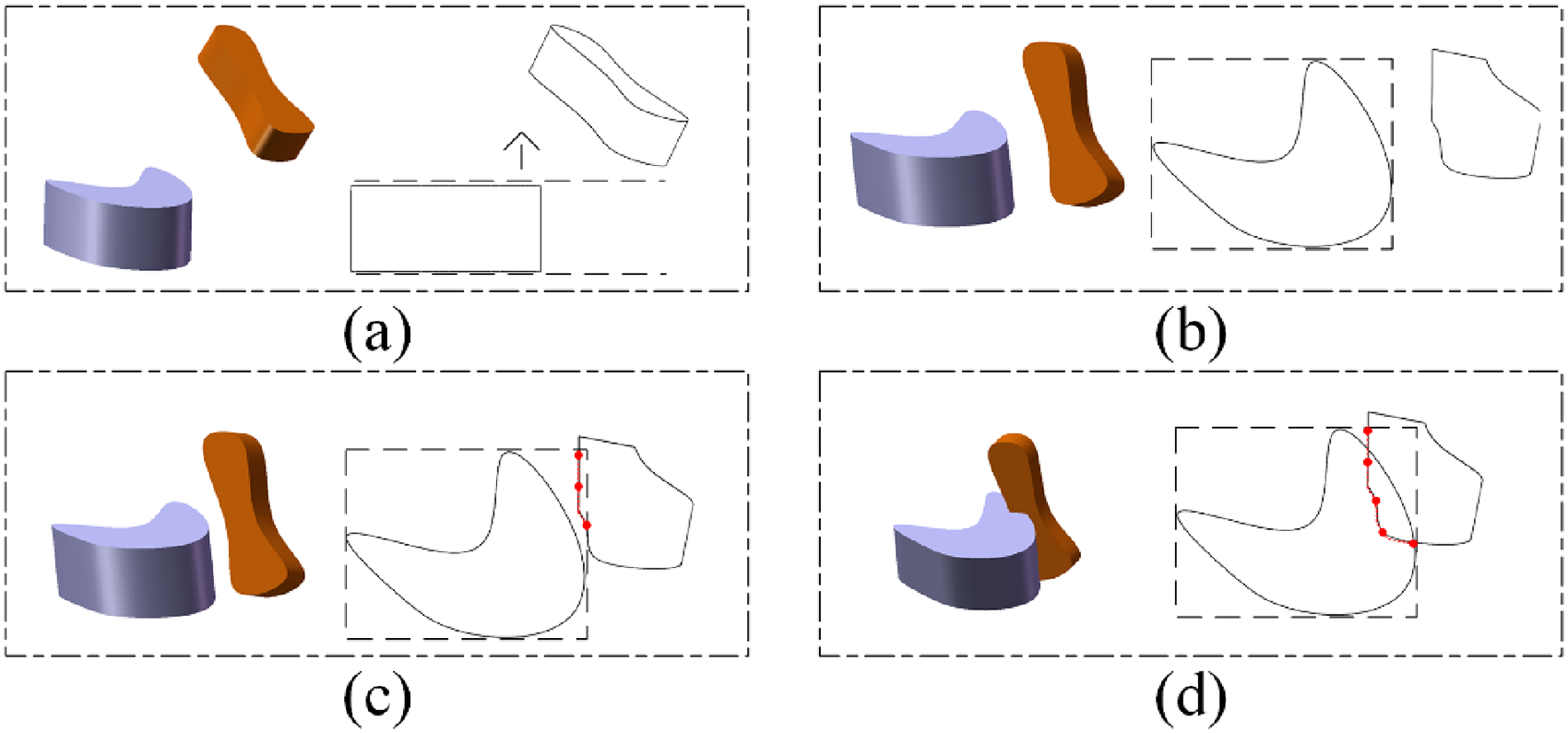
Collision detection between two stretched bodies.
Simulations
To evaluate performance of PCSP method, other typical methods were simulated and compared. They are respectively based on CPPs, GJK, KDtree, k-DOP, OBB, and AABB. The CPPs method uses cylinders to represent manipulator links and uses numerous convex plane polygons to represent surrounding objects, where the collision detection is determined based on spatial relationship between cylinder generatrix and polygons. The GJK method approximates an object using a convex hull and is widely applied to obstacle-avoidance motion planning of robot manipulators. KDtree method directly utilizes the original point cloud, which is theoretically suitable to any scenarios and can attain the 100% accuracy at the expense of running time. So, the accuracy performance of PCSP was mainly evaluated on the basis of it. The k-DOP method uses the fixed direction convex hull to approximate all objects. OBB uses orientation bounding box to approximate all objects while it has a fast collision detection. AABB uses align-axis bounding box to approximate all objects while its construction is the fastest.
All of the experiments were performed on a computer with 11th Gen Intel(R) Core i5-1135G7 2.40 GHz CPU, 16.0GB RAM, Windows10 Operating System.
As shown in Figure 10, an application scenario for robotic manipulators was set up to evaluate the performance of collision detection methods. First, we randomly generated links and end effectors in the application scenario. Second, we classified them into positive states (collision with obstacle) and negative states (no collision with obstacle) using high-resolution point clouds, which was at the cost of high computational time. Finally, we utilized these states to evaluate the true positive rate (TPR), the true negative rate (TNP), and the computational time of collision detection methods. The application scenario in Figure 10 was set up based on an overhead transmission line and contained four lines, four hydraulic clamps, four dampers, and one spacer. In the simulation, 1000 manipulator links and 1000 end effectors were randomly generated for each state. The random sampling space was 0 to 6 m at x-axis, 1.5 to 2.5 m at y-axis, 0 to 1 m at z-axis. The radius of the links ranged from 0.005 to 0.1 m and the length of the links ranged from 0.1 to 1 m, which covered the size of most of manipulator links. The resolution of the point clouds was set as 0.001 m, which was acceptable for the real-world application.

An application scenario for robotic manipulators to evaluate the performance of collision detection methods. (a) The scenario contained four lines, four hydraulic clamps, four dampers, and one spacer. The red arrow represented x-axis, the green arrow represented y-axis, and the blue arrow represented the z-axis. (b) The random generation of capsule links for the simulation in the scenario. (c) The random generation of end effector shapes for the simulation in the scenario.
We firstly selected optimal parameters for mentioned methods in our work. There are two major parameters for CPPs. The one is the number of generatrix to approximate the cylinder link and the other one is the number of polygons to approximate the curved surface. For example, eight polygons were used to approximate the common curved surfaces in Figure 11. We selected the number of polygons and set it from 4 to 13 while the number of generatrices was set as 100. The simulation results were illustrated in Figure 12. The TPR and the TNP considerably increased at the beginning and leveled off with the number of polygons. Larger the number of polygons is, higher they can reach. The TPR finally was higher than the TNR because we used a larger geometric body to envelope the original object. The TPR and TNR are more than 99.0% when the number of polygons is more than 8. But there was no evident increase from 8 to 9, and the time expense was in proportion to the number of polygons. So, eight polygons were selected for the CPPs to approximate a curved surface. Obstacle representation based on the CPPs was illustrated in Figure 13(b).
Curved surfaces approximated by eight polygons.
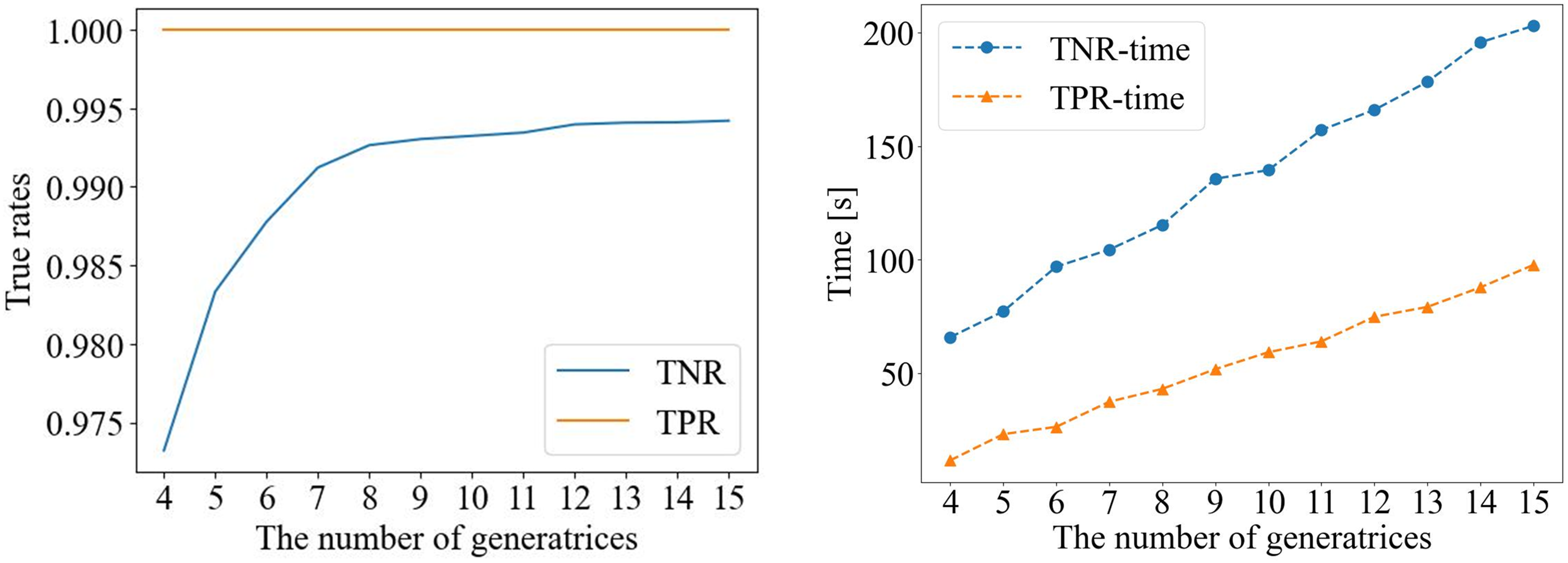
Performance of CPPs with the numbers of generatrices and polygons. CPP: convex plane polygon.
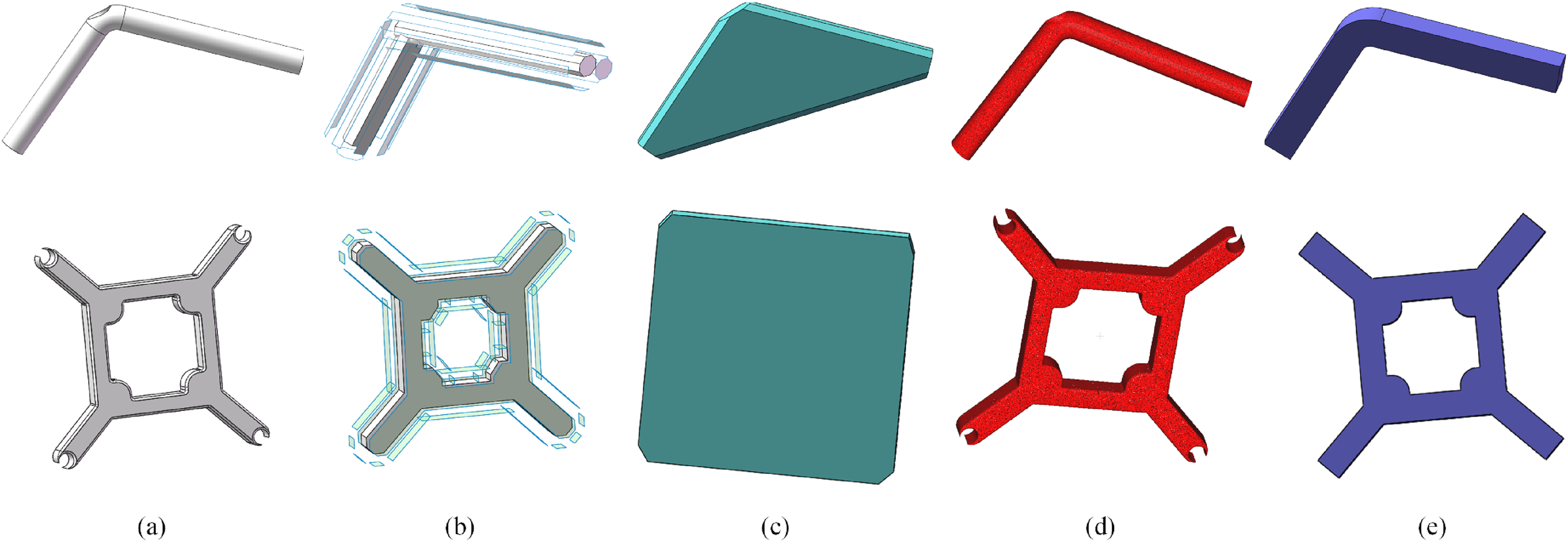
Obstacle representation for different methods. (a) Original models; (b) models for CPPs; (c) models for GJK; (d) models for KDtree; and (e) models for PCSP. CPP: convex plane polygon; GJK: Gilbert–Johnson–Keerthi; PCSP: point clouds and stretched primitives.
For GJK, the parameter is the number of directions to envelope an obstacle by a convex hull, and obstacle representation was illustrated in Figure 13(c). The parameter for KDtree was the number of layers to construct a tree, and the obstacle was represented by the point cloud, as illustrated in Figure 13(d). The parameter was the number of sampling points for PCSP, and all obstacles were processed into the stretched geometric body in Figure 13(e). Procedures of determining the optimal parameter of each algorithm are shown in Figure 14. Simulation results are shown in Table 1, which recorded the TPR, the TNR, and the time expense of four methods in the overhead-line scenario.
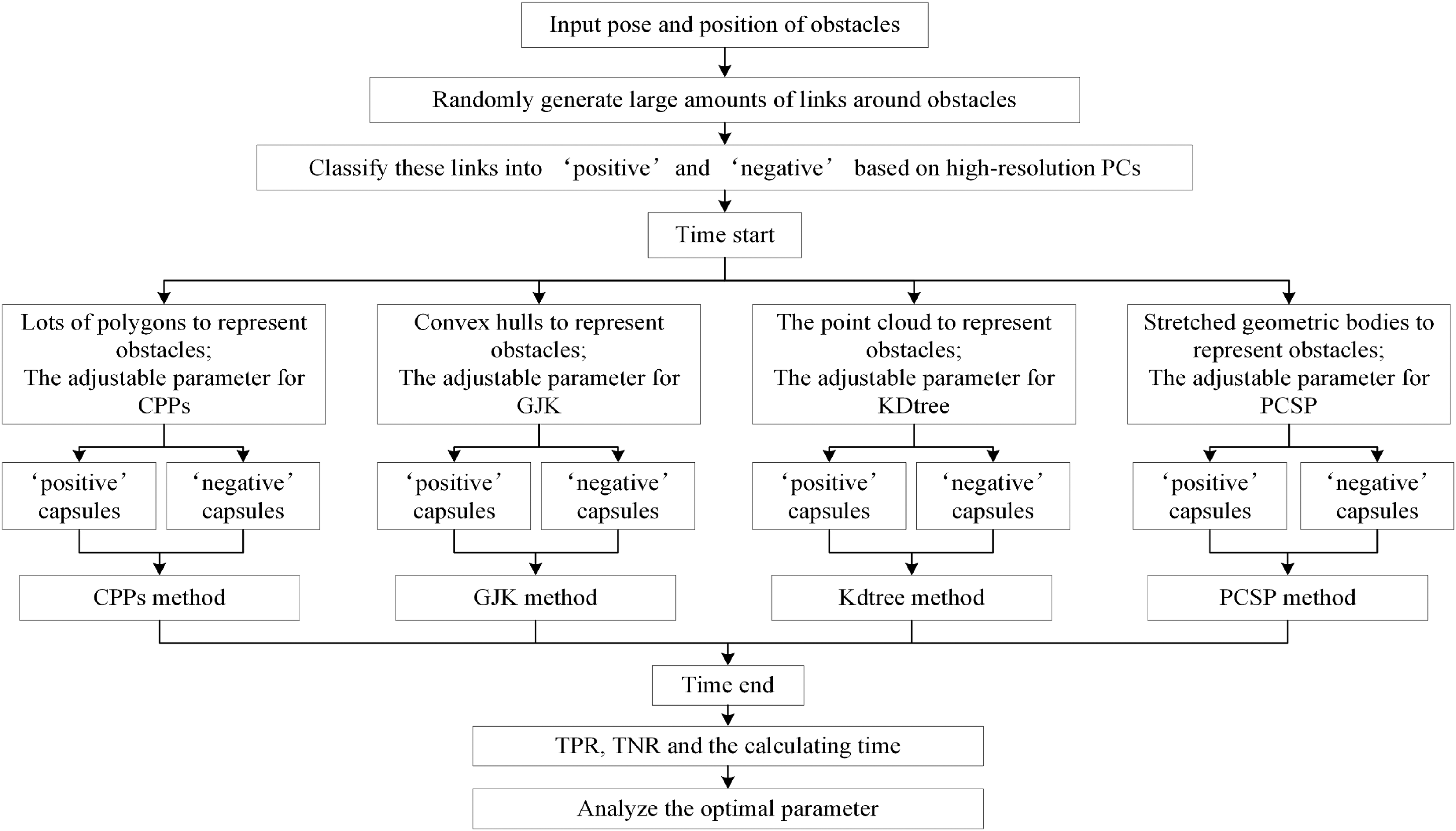
Procedures of determining the optimal parameter of different methods.
Parameters selection for different methods.

CPP: convex plane polygon; GJK: Gilbert–Johnson–Keerthi; NG: number of generatrices; ND: number of directions; NL: number of layers; NS: number of sampled points; PCSP: point clouds and stretched primitives; TNR: true negative rate; TPR: true positive rate.
All methods reached 100% TPR as long as we gave an enough high parameter, and GJK always kept at 100% because of its large bounding volumes. However, it is quite different when it comes to TNR. For the CPPs method, the TNR decreased with the number of generatrices and finally reached 99.1%. For the GJK method, the TNR increased with the number of directions and only reached 89.8%. For the KDtree method, the TNR always kept at 100% because it substantially sampled some critical points from the point cloud to perform the collision detection. For the PCSP method, the TNR decreased with the number of sampling points and reached 98.8%. The upper of the TNP depends on the degree of approximation to the original object. It is potential to reach 100% but generally computationally expensive when numerous polygons or points are used, such as CPPs and KDtree methods. By contrast, there is accuracy loss but it is fast when bounding volumes are used, such as GJK and PCSP methods. As shown in Table 1, we selected the parameter for each method, in which the accuracy holds steady. In this case, GJK and PCSP have TPR time less than 2 s and have TNR time less than 6 s, whereas CPPs and KDtree have TPR time more than 10 s and have TNR time more than 30 s. Furthermore, the proposed PCSP has higher TNP than GJK although they have similar time expense.
The end effector was a concave polyhedron, which was quite different from the capsule-shape link. By contrast, all methods spent more time to perform collision detection because of extra model processing. For CPPs, each face of the polyhedron was treated as the unfolded cylinder surface, in which the polyhedron was approximated by numerous generatrices. For GJK, the polyhedron was divided into three convex bodies. For KDtree, it was still based on the point cloud but its time expense was still the most. For PCSP, the projection profile was extracted along the stretched direction of obstacles. However, PCSP still had a good comprehensive performance. In terms of TNR time, PCSP was 9.518 s, which was similar to GJK but obviously less than CPPs and KDtree. In terms of the TNR, it was about 98.6% similar to CPPs and KDtree but obviously higher than GJK.
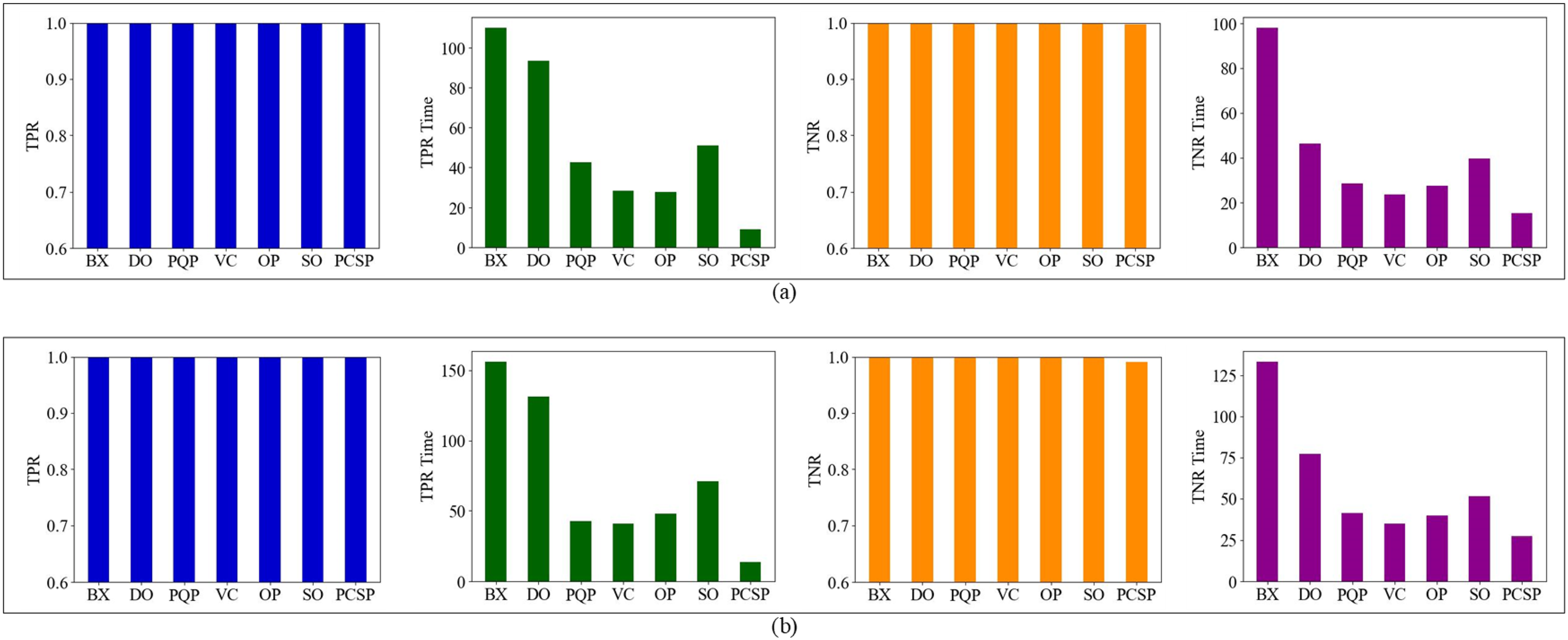
We selected the optimal parameter for all methods to further estimating the PCSP, in which the true rate was steady and computing time was not much. The parameter was 24 for CPPs, 14 for GJK, 18 for KDtree, and 50 for PCSP. In the simulation, we implemented all methods to perform collision detection for the manipulator in the overhead quadruple-line scenario. As depicted in Figure 15, two manipulators were modeled, in which one was a self-made manipulator named as JKPT and the other one was a commercial manipulator named as HRE10. We randomly generated 1000 configurations for every manipulator while each configuration was labeled as “positive” or “negative” by high-resolution point clouds. Our proposed method was suitable for different robotic manipulators, which approximated the end effector and complex links by stretched geometric bodies and treated simple links as capsules. The comparison of our method with other methods is shown in Figure 16.

Two manipulators and their links representation. (a) A self-made manipulator named JKPT. (b) A commercial manipulator named HRE10.
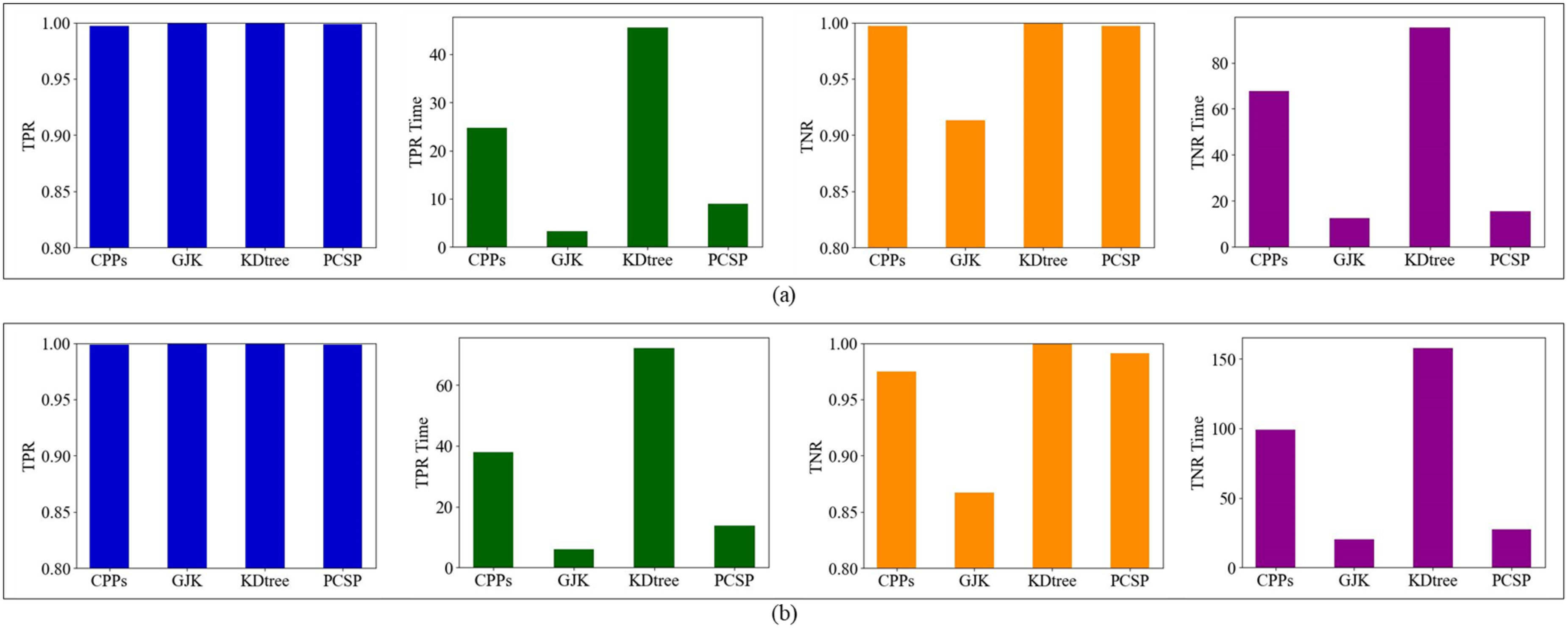
The accuracy and the computing time of different methods: (a) for JKPT and (b) for HRE10.
Figure 16(a) displayed the results of all methods for JKPT. Each method achieved a 100% TPR, but they are different in TNR and computing time. KDtree achieved a perfect 100% TNR at the cost of the most computing time. Conversely, GJK was the most time-efficient but exhibited the lowest TNR. Both CPPs and PCSP demonstrated a 99.9% TNR while also requiring less time than KDtree. Notably, PCSP demonstrated a TNR time of 20 s, which was comparable to that of GJK method. Figure 16(b) displayed the results of all methods for HRE10, whose links are more complex than those in JKPT. The TNR of CPPs and GJK exhibited reductions of over 5%, but PCSP only experienced a slight decline of 0.4%. Although KDtree maintained a 100% TNR, its time expense was five times greater than that of PCSP. Hence, PCSP features a high TPR, a high TNR, and low time expenses. We also applied typical bounding-volume methods, containing k-DOP, OBB, and AABB. In this article, we used the 18-DOP, which has been shown to be the best. 37 As illustrated in Figure 17, these bounding-volume methods were faster than PCSP, but they sacrificed a significant amount of TNR to achieve a 100% TPR. Specifically, the TNR of these methods applied to the HRE10 was less than 80%. The hierarchical technique was commonly utilized to improve the accuracy of these bounding-volume methods. As illustrated in Figure 18, we applied six freely available collision detection libraries that were based on bounding volume hierarchies, and they had 100% TPR and 100% TNP. The abbreviations for the libraries are as follows: BX = BoxTree, 49 DO = Dop-Tree, 50 PQP = Proximity Query Package ,51,52 VC = V-Collide, 53 OP = Opcode, 54 SO = FreeSOLID.55,56 BX, OP, and SO are based on AABB, while PQP and VC are based on OBB. The DO library is based on k-DOP that uses discrete oriented polytopes as bounding boxes. However, they spent more time than PCSP that approached 100% accuracy, in which VC was over 1.5 times as much as PCSP, although it spent the least time than other libraries. Therefore, PCSP is more suitable than the other methods when planning a manipulator with concave links or end effectors in a quadruple-line scenario.

The accuracy and the computing time of bounding volume methods: (a) for JKPT and (b) for HRE10.
The accuracy and the computing time of bounding volume methods with the hierarchical technique: (a) for JKPT and (b) for HRE10.
Most of the collision detection algorithms are very sensitive to specific scenarios. Therefore, it is necessary for our proposed method to evaluate the performance in general scenarios. Trenkel et al. 33 presented a standardized benchmarking suite for collision detection to make fair comparisons between algorithms. In this article, we also utilized the suite to evaluate the performance of our proposed method, where the dataset was downloaded from the website. 57 Unlike the above specific scenario that tested 16 pairs for JKPT and 24 pairs for HRE10, we simply tested a model against a copy of itself by the standard suite in general scenarios.
Comparison results are illustrated in Figure 19, in which our proposed method was compared with six freely available collision detection libraries. BX, OP, and SO are based on AABB, while PQP and VC are based on OBB. DO library is based on k-DOP. We can find that all algorithms have their special strength and weakness in different objects. For the castle and the grid, they had approximatively regular shapes while the AABB-based libraries behaved well. For the apollo and the ATST, they had concave shapes and lots of small details while the OBB-based libraries and our proposed method behaved well. The DO library combines the fast test of the AABB with the tight approximation of the OBB. As expected, it ranked between the other two kinds of libraries in most of the test scenarios. However, for the ATST with a more concave shape, the DO library performed much better than the other libraries.

The results of the benchmark in different scenarios, the castle with 127131 vertices, the grid with 414720 vertices, the apollo capsule with 163198 vertices, and the ATST walker with 20132 vertices. The x-axis denoted the relative distance between the objects, where 1.0 was the size of the object. Distance 0.0 meant that the objects were almost touching but did not collide.
Compared to the six libraries, our proposed method performed best for objects with concave shapes like the apollo and the ATST. Although it behaved much worse than other libraries for the collision detection of a pair of castles, it spent similar calculating time to other objects. For all objects, our proposed method behaved consistently in terms of calculating time, and it converged when the relative distance was more than 0.08. Hence, our proposed method is not sensitive to the shapes of objects and mainly influenced by the relative distance between a pair of objects. The main drawback of our proposed method is that it may spend a little more time than other libraries when the distance is large. As is well-known, if the bounding volume of an object does not intersect a volume higher in the tree, then it cannot intersect any object below that node. Thus, collision detection libraries based on BVHs perform very efficiently when a pair of objects is far apart. In contrast, our proposed method is inferior to these libraries when objects are far apart, because its contour extraction procedure increases the minimum time. However, the increase has a little impact on manipulator obstacle-avoidance planning because objects in manipulator's workspace are generally concave and close together. To sum up, our proposed method is more appropriate when a pair of concave objects is close together.
As for the dependency on the complexity of the objects, Trenkel's study 33 indicated that the libraries had no general tendency. We conducted a similar test for our method in different resolutions of these objects. As illustrated in Figure 20, the calculating time of our proposed method exhibited nearly linear with the number of vertices at the beginning, and then it reached to a plateau. The performance is as expected. A small number of vertices results in a simplified model and a simple contour, which enables efficient procedures of the contour extraction and the latter collision detection. A large number of vertices will increase the calculating time due to the detailed shape. However, a huge number of vertices have little impact because most of them are projected into a pixel before the contour extraction. It is helpful for implementation that our method has the above dependency on the complexity of the objects. In general, more vertices are expected to provide accurate collision detection, although fewer vertices require less time. In particular, an original mesh model or a point cloud from sensors is always redundant to represent an object. Hence, our proposed method has advantages in practical application.

The dependency of the collision detection time on the complexity of the models in different scenarios. The distance was fixed to 1% relative to the object size. The x-axis denoted the number of vertices divided by 1000.
Implementation
In our work, we hope a manipulator with X-ray device to detect four clamps fixed on overhead lines. As shown in Figure 21, the interval of the four lines is 450 mm while the width of X-ray end effector is 300 mm. The clamp has a concave shape. It was infeasible when we directly used bounding volume method, and it was inefficient when we directly used the original point cloud. So, PCSP was implemented to reconstruct the surrounding objects, and provided the obstacle-avoidance path for a manipulator. As shown in Figure 22, we recognized four clamps and obtain its original 3D points by the Intel RealSense D435I camera, and then PCSP generated the stretched body from the original point cloud while performed collision detection for autonomous motion planning. To achieve a good performance of motion planning in the narrow workspace, the motion planning involved two stages. In the first stage, a feasible path was planned based on an adaptive rapidly exploring random tree, which coped well with the narrow workspace in the quadruple-line scenario. 58 In the second stage, we generated a smooth and collision-free motion based on the numerical optimization, in which the planned feasible path was approximated by a quintic polynomial trajectory whose coefficients were solved by convex optimization algorithms. Figures 23 to 25 illustrated the planned motion for our self-made manipulator that was composed of three translational joints and two revolute joints. For the planned motion, the minimum distance between the manipulator and surrounding objects was shown in Figure 26, which indicated PCSP provided an obstacle-avoidance path for the manipulator. Furthermore, the manipulator successfully executed the planned motion. As shown in Figure 27(a) to (d) showed the process of detecting the first clamp; Figure 27(e) to (g) showed the process of detecting the second clamp; Figure 27(h) to (j) showed the process of detecting the third clamp; Figure 27(k) to (m) showed the process of detecting the fourth clamp; Figure 27(n) to (p) showed the process of returning the zero state.

The overhead four lines, four clamps, and the X-ray end effector.
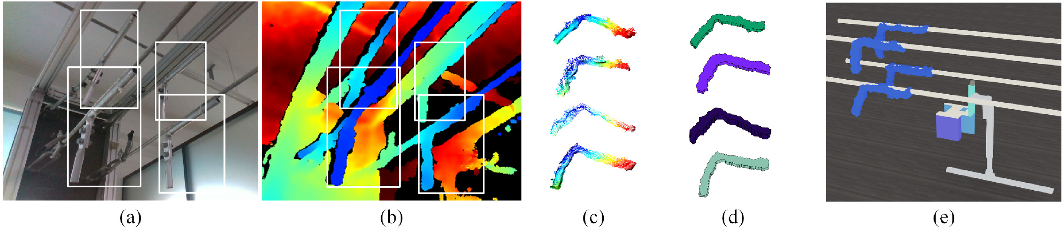
Stretched geometric bodies construction for clamps and motion planning for the JKPT. (a) The RGB image. (b) The depth image. (c) Point clouds of four clamps. (d) Stretched geometric bodies of four clamps that were generated by PCSP method. (e) Overhead scenario reconstructed by the PCSP for obstacle-avoidance motion planning. PCSP: point clouds and stretched primitives.

Position curves of three translational joints and two revolute joints.

Velocity curves of three translational joints and two revolute joints.

Acceleration curves of three translational joints and two revolute joints.

The minimum distance between the manipulator and surrounding objects for the planned motion.

The motion process of detecting four clamps. (a) to (d) The process of detecting the first clamp. (e) to (g) The process of detecting the second clamp. (h) to (j) The process of detecting the third clamp. (k) to (m) The process of detecting the fourth clamp. (n) to (p) The process of returning the zero state.
Conclusions
In this article, a collision detection method based on the PCSP is presented to improve the performance of manipulator obstacle-avoidance motion planning. This method contains objects representation and geometry intersection judgment. In the PCSP method, obstacles and complex links are enveloped by the stretched geometric bodies and simple manipulator links are treated as capsules with different sizes. Geometric primitives are extracted from the original point cloud. Collision detection between the manipulator and surrounding obstacles is converted to intersection judgments among simple geometries. PCSP is able of coping with concave obstacles directly. Experimental results indicated that PCSP had a low computing time and kept a high accuracy. Compared with state-of-the-art collision detection methods that have a high accuracy, PCSP is three times faster than the KDtree, two times faster than CPPs, while it has 100% TPR and 98% TNR. A standard benchmark test showed that PCSP was superior to libraries based on BVHs when concave objects are close together, and had advantages in practical applications where the number of mesh vertices or points from sensors was huge.
The main disadvantage of PCSP was that it is inferior to other methods based on the bounding box when objects have convex shapes or a pair of objects is far apart. PCSP has a higher minimum time because of the contour extraction procedure, whereas other methods perform very efficiently if a pair of convex objects is far apart. As has been analyzed for simulation results, the proposed method is appropriate in narrow workspaces so that it can be easily applied in environments with multi-manipulators or a large number of static obstacles. However, for multiple robots like UAVs, the workspace is generally large and dynamic obstacle avoidance is required. In addition, it is more challenging for a deformable object to dynamically construct its shape. To address these issues in general scenarios, we think it is a possible strategy to tightly integrate the proposed method with the hierarchical technique and the velocity obstacle concept, which is also part of our future work.
Footnotes
Author contributions
All the authors contributed to the study conception and design. PY collected the data, performed the analysis, and wrote the manuscript. FS, DX, and RL commented on previous versions of the manuscript and critically revised the work. All authors read and approved the final manuscript.
Declaration of conflicting interests
The authors declared no potential conflicts of interest with respect to the research, authorship, and/or publication of this article.
Funding
The authors disclosed receipt of the following financial support for the research, authorship, and/or publication of this article: This work was supported by the Electric Power Research Institute from the Yunnan Power Grid Co Ltd, Kunming, China (Project No. YNKJXM20180730) and the Natural Science Foundations of China, Yunnan Power Grid Company (grant number 61573117, 61673128).