In this article, an adaptive iterative learning control (AILC) scheme has been proposed to enhance the accuracy of the dynamic path tracking of 6-degrees of freedom industrial robots. Based on the memorized data and current feedback from a three-dimensional visual measurement instrument, an adaptive algorithm is developed to update the time-varying control parameters of the AILC scheme iteratively. A new compensation signal is calculated to adjust the control inputs produced by the dynamic path tracking control module at each time interval. Through the adaptation algorithm, the identical initial conditions can be relaxed to some extent with the AILC scheme. Moreover, the stability analysis of the proposed AILC scheme is presented. Experimental results on FANUC M20iA, using C-Track 780 as a photogrammetry sensor, demonstrate the superior performance of the developed AILC scheme in terms of pose accuracy, disturbance rejection ability, and control performance.
In aerospace manufacturing, robot manipulators are extensively employed to repeat program-planned tasks and the task paths for them tend to be repetitive. It is the scenario for the researchers to apply iterative learning control (ILC) strategy. Many early research works on ILC, such as Arimoto1 and Bien and Huh,2 require some priori information of the system and rely on the two-dimensional contraction mapping theory. The principle of ILC is to acquire better performance through iteratively adjusting control input to the plant based on the status error and control information of previous iterations by Bristow et al.3 The performance of ILC is improved as the states’ errors converge to zero asymptotically along the iteration axis. Both transient response and tracking performance can be improved by ILC especially for repeating disturbances and system model uncertainty. In comparison to a feedback controller, ILC can avoid the lag in the transient phase since the previous information enables ILC to anticipate the control adjustment. ILC is similar but superior to a feedforeward control for overcoming the unknown repetitive disturbances. Actually, ILC can be regarded as a feedback control in the iteration domain, as a result it can be robust to the system model uncertainty. However, ILC cannot excel in non-repeating noise or disturbances comparing to a feedback control. Therefore, ILC combined with a feedback control can be appropriate for both repeating and non-repeating disturbances.
Inspired by the research on Lyapunov and Lyapunov-like methods in control fields, an adaptive ILC (AILC) method has emerged in recent decades. The AILC method is designed to estimate the uncertain parameters of robot manipulators iteratively. For instance, a robust AILC method for three-link de-icing robot manipulator is introduced to predict the desired control torques with switching adaptive gain from iteration to iteration by Ngo and Tran4 as tracking the desired trajectory. In the research work,5,6 the unknown parameters can be updated in time domain during each run and the repeated disturbances can be overcome along the iteration axis. However, the same issue for the AILC method in these research as that for the traditional adaptive control method is the requirement on the constant unknown parameters. To address this issue, the AILC method with time-varying parameters is proposed for nonlinear systems through iterations, for example, by Xu,7 Liu et al.,8 Lee et al.,9 and Huang et al.10 For instance, according to Liu et al.,8 external disturbances are estimated by ILC updating law, while uncertain parameters are adaptively compensated along time axis for a 2-degree of freedom (2-DOF) manipulator. Unfortunately, for a complex nonlinear system such like a 6-degree of freedom (6-DOF) industrial robot, the preliminary conditions such as Lipschitz continuous condition, is not applicable. Based on a comprehensive review of existing literature, there is very few research targeting 6-DOF industrial robots and providing experimental exploration.
The dynamic path tracking (DPT) control scheme presented by Shu et al.11 is essentially a feedback control. The transient performance of the DPT control scheme is not ideal due to startup acceleration. Also, unexpected vibrations appear for the DPT control scheme when the end-effector of the industrial robot is moving with higher speed. In this article, an AILC scheme is proposed to pursue dynamic path tracking with high accuracy and superior control performance for 6-DOF industrial robots. An adaptive updating law for a parameter vector including time-varying parameters through iterations is designed. The time-varying parameters may implicitly contain the information from the system dynamics and repeated disturbances. The experimental results on a 5-DOF CRS255 robotic manipulator at speed 1.41 mm/s presented by Tayebi and Islam12 show high frequency oscillations existing in the control inputs on 25th iteration. The oscillations are attributed to the noise accumulation and low velocity approximation in the measurement. In this article, an adaptive Kalman filter is applied to provide well-filtered real-time estimations of the poses and velocities of tool center point (TCP) of the end-effector. In addition, the AILC scheme is integrated with the DPT control scheme to reject both repeating and non-repeating disturbances.
One common problem in the ILC is that the initial conditions of state errors are random which cannot be set as identical in each iteration. The worst case of five types for initial conditions mentioned by Xu7 is that the initial errors are randomly variable but subject to constant limits. The reconstruction of initial reference by using a rectification method is presented to overcome existing initial errors in a neuro AILC scheme.13 In this article, initial conditions are random and bounded while initial errors are generated by the first round of the DPT control. The DPT control has been verified to be effective for suppressing the path tracking errors under certain small values and repeatable to a great degree. Therefore, although identical initial conditions cannot be satisfied, the initial errors can be initialized to be less than the max errors achieved by the DPT control module. The path tracking accuracy with the DPT control scheme can be up to mm for position and for orientation when the moving speed of the end effector is around 25 mm/s by Shu et al.11 The proposed AILC scheme can be robust to the initial shifts. The AILC scheme aims to compensate the DPT control scheme for obtaining better transient performance and path tracking accuracy through iterations. Moreover, the stability of the AILC algorithm is analyzed in this article. On the other hand, the distance error for path tracking of the end-effector with the AILC control scheme can be < 0.1 mm at speed 50 mm/s due to the improvement of the transient performance and consistent convergence for both position error and orientation error along the iteration axis.
The rest of this article is organized as the following. First, the problem statement includes the dynamic state equations of 6-DOF manipulators, relevant properties. Second, the control configuration of the AILC scheme in parallel with DPT scheme, AILC algorithm and stability analysis are presented. Then, the experiments on FANUC M20iA by using C-track 780 to provide visual measurements are implemented and the demonstration of the experimental results proves the effectiveness of the AILC scheme. Finally, the concluding remarks and future works are given.
Problem statement
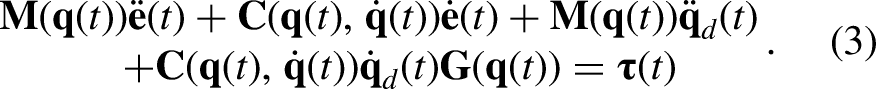
The general dynamic model of 6-DOF manipulators14 is described by the following equation:
where , , and represent the robot joint angles, velocity, and acceleration, respectively; is a positive-definite and symmetric inertia matrix; denote centrifugal and Coriolis torques, respectively; is the gravitational torques; and denotes control torques.
At the same time, equation (1) has the following common properties14:
Property 1: is the positive-definite, symmetric, and bounded as . and are existing positive constants.
Property 2: is the skew-symmetric, and . is a positive constant.
Property 3:. is positive constant.
Property 4: The left part of equation (1) can be written in a linear form to the system parameters as
where is regressor matrix can be obtained when , , and are available, is the vector of h system parameters.
Define , and is the desired reference. Then, the error dynamics can be written as follows:
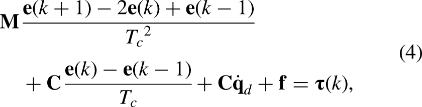
Assume that . The discrete form of equation (3) can be written as follows:
where for convenience, , , and denote , , and respectively; which is bounded according to Property 1 and 3.
According to the observation of the experimental results introduced by Shu et al.,11 the end-effector fails to initially follow the desired path with high accuracy. It is assumed the finite time span T for each iteration is constant. The aim of the AILC scheme is to reduce during through iterations. Accordingly, path tracking accuracy can be further improved by integrating the AILC scheme with the DPT control scheme. At the same time, system parameters vector is assumed to be unknown. On the other hand, the adaptive Kalman filter (AKF) algorithm designed by Shu et al.11 is utilized to real-time filter the pose measurements obtained from visual measurement instrument (VMI) in the implementation of the AILC scheme. The sampling interval of the VMI is denoted as . Ideally, can be regarded as a constant. However, tends to be variable. Assuming that represents a fixed filter interval. is a strategy to reduce the influence of time delay resulted from the irregular sampling interval.
AILC for DPT
Figure 1 demonstrates the control configuration of dynamic path tracking by using the AILC scheme to compensate the DPT control scheme. Comparing to the control configuration of the DPT control scheme, the significant difference is the upper block including the AILC module and learning memory. Based on the saved pose error information and control input of former iteration, the AILC algorithm module produces control input of current iteration to compensate the control input of the DPT control module. The adaptive vector of the AILC algorithm is designed to include time-varying parameters which can be updated through iterations and reflects the system dynamics and repeated disturbances without knowing the system parameters. In order to reduce the noise effect, an adaptive Kalman filter is utilized for processing pose estimation. Moreover, the function of path analyzer is used to obtain current desired pose according to the desired path and current pose of the end effector.
Control configuration of the AILC scheme integrated with the DPT control scheme for dynamic path tracking of industrial robots. AILC: adaptive iterative learning control, DPT: dynamic path tracking.
AILC algorithm
The state error at time k for iteration m is defined as . Then, the control objective of the AILC algorithm is when . can be obtained as follows:
where and are the current estimated pose from AKF and the desired pose. The error dynamic equation (6) for joint i, in iteration can be written as follows:
where . Then, according to equation (8), the ideal controller for joint i can be designed as follows:
where are control gains. related to system parameters is assumed to be unknown. the AILC law is designed to compensate the control input of DPT control module as follows:
where is the estimation of and .
Stability analysis
The stability proof of the proposed control algorithm through iterations can be based on positive definite Lyapunov-like energy function (LEF) by ensuring monotonic decreasing of LEF under some conditions which has been introduced by Xu15 and Tayebi.16
Let . The Lyapunov-like function candidate for each iteration between can be defined as follows:
Submitting equation (12) into equation (8), can be obtained as follows:
Moreover, when , using equation (13), can be updated as follows:
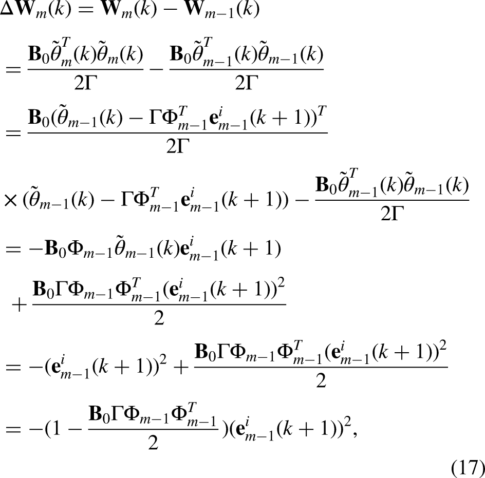
According to equations (14) to (16), the iteration-decreasing trend of along the iteration axis can be proved as follows:
which is less than 0 if only . Therefore, when . According to equation (15), when , it is clear that .
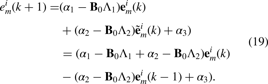
On the other hand, when , the control law equation (12) becomes
Using equation (8), the closed-loop dynamics becomes
Define , , and , then one has
Apparently, if only , are selected such that the eigenvalues of A are within the unit circle, then equation (19) is stable, and is bounded.
In conclusion, the closed-loop system with the proposed AILC scheme can be stabilized within each iteration over the time span T. Additionally, the iterative control process consistently converges when as . Consequently, dynamic path tracking with high accuracy can be achieved after a limited number of iterations with the proposed AILC scheme.
Experimental results
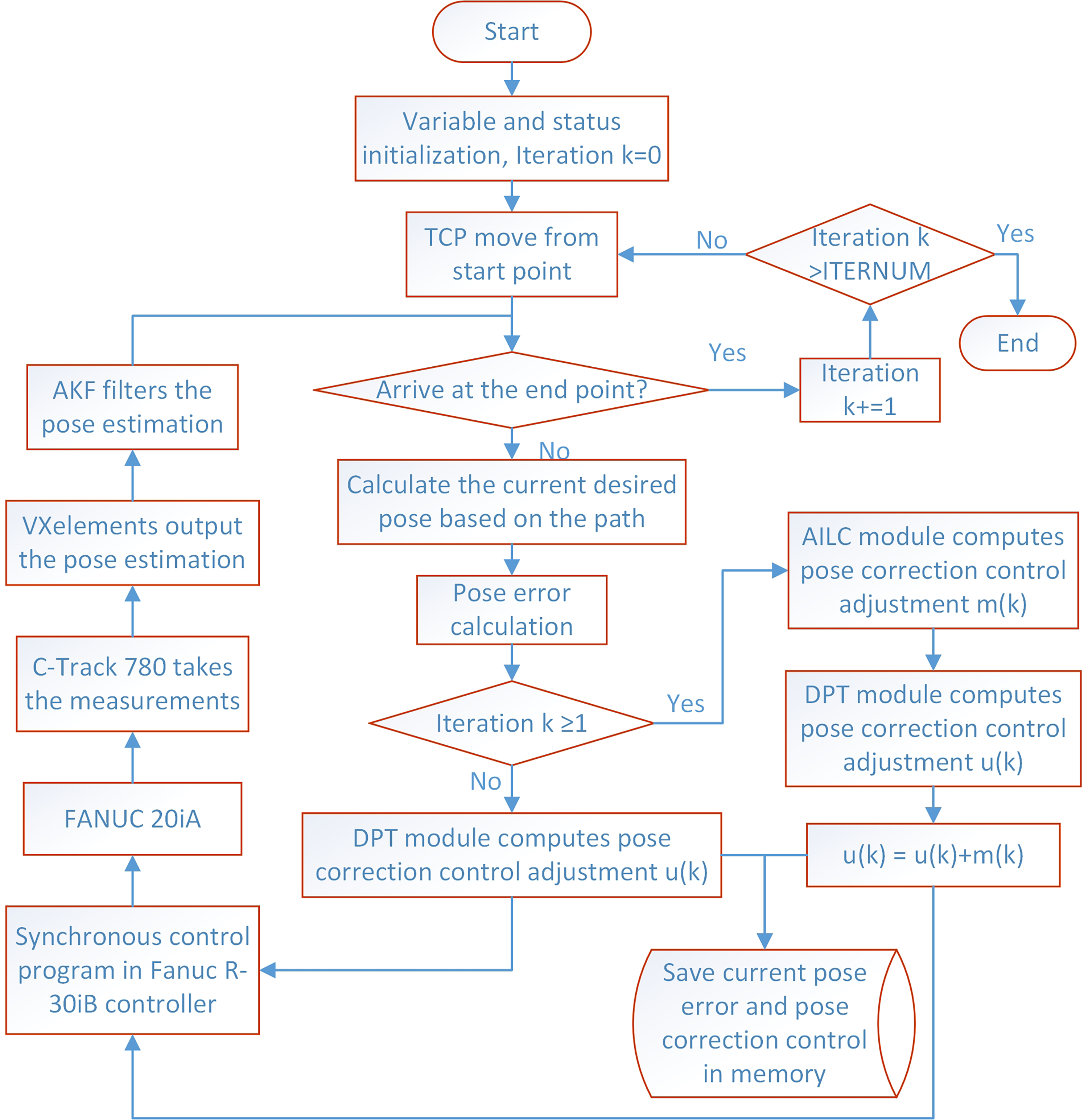
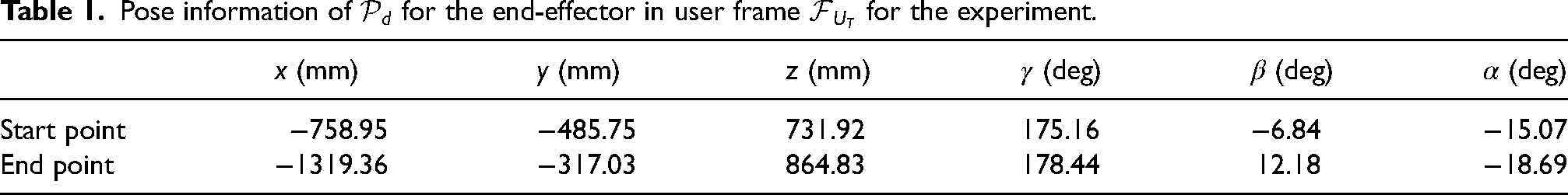
In order to verify the efficiency of the proposed AILC scheme (Figure 2), some experiments have been carried out for controlling the TCP of the end-effector to move along a typical desired task path in the workspace of FANUC M20iA. Figure 3 demonstrates the experimental setup and the inclusive hardwares. FANUC M20iA, Figure 3(a), is a serial actuator including six rotational joints with maximum payload at wrist 20 kg, while the end-effector attached to the tool flange of FANUC M20iA is demonstrated as Figure 3(b). C-Track 780 as shown in Figure 3(c) is a dual-camera photogrammetry sensor, which can provide real-time three-dimensional measurements. The reflectors sticked on the end-effector work as image features for C-Track 780 to detect the pose of end-effector. The desired task path is described in Table 1. The experimental results are showcased across three scenarios: without dynamic path correction, with the DPT control scheme alone, and with the AILC scheme integrated. The control flowchart for implementing the AILC scheme is shown in Figure 2.
Control flowchart for implementing the adaptive iterative learning control (AILC) scheme.
Experimental setup, (a) FANUC M20iA, (b) end-effector with adhesive reflectors, and (c) C-Track 780 on a tripod.
Pose information of for the end-effector in user frame for the experiment.
x (mm)
y (mm)
z (mm)
(deg)
(deg)
(deg)
Start point
−758.95
−485.75
731.92
175.16
−6.84
−15.07
End point
−1319.36
−317.03
864.83
178.44
12.18
−18.69
Parameters initialization
The maximum updating frequency of C-Track 780 for measuring the pose of a object with VXelements is 29 Hz. Accordingly, the filter interval of AKF is initialized to be 12 ms which is approximately close to s. Based on the testing on C-Track 780, the sampling interval with VXelements is not strictly s and the time difference between two continuous sampling intervals can be in ms. Compared to the control interval configured by Shu et al.,11 for the experiments to implement the AILC scheme is set as 3 times of the sampling time in order to generate rapid control signal to accommodate the higher moving speed of the end-effector. The moving speed of the end-effector applied in this research is 50 mm/s, while the moving speed of the end-effector for the experiments to verify the DPT control scheme by Shu et al.11 is 25 mm/s. Control gains and for six axes are set as and , respectively. Adaptive learning parameters are initialized as 0 and positive learning gain is selected as 1.5. Greater values of the learning gain parameters may accelerate the convergence rate. However, the influence of the noises appearing through iterations can be magnified and cause vibrations for the movements of the joints. The worst case is the divergence of the learning process.
The analysis of experimental results
Path tracking without dynamic path correction
The first experiment is conducted for the TCP of the end-effector moving along at speed 50 mm/s without dynamic path correction and the error analysis of the experimental results are demonstrated in Figures 4 to 6. According to Figure 4, the maximum distance error at speed 50 mm/s without dynamic path correction is over 2.5 mm, which is greater than the maximum distance errors at speed 25 mm/s by Shu et al.11 The divergence patterns of position error along the x and z in user frame are similar. However, the divergence range of position error along the z-axis is up to 2.541 mm which is much greater than the maximum error 0.628 mm along the x-axis. Moreover, there are obvious vibrations shown on the position error along the y-axis in Figure 5 although the maximum error along the y-axis is < 0.2 mm. The maximum divergence range of orientation error without dynamic path correction is up to 0.254° which is from the rotation angle around x-axis of despite of the fact that the desired orientation is unvarying along . On the other hand, the experimental results without dynamic path correction validate the observations by Shu et al.11 that tracking different paths exhibits different error patterns and the distance error increases with higher tracking speed.
Distance error for FANUC M20iA moving forward along at speed 50 mm/s without path correction.
Position error for FANUC M20iA moving forward along at speed 50 mm/s without path correction.
Orientation error for FANUC M20iA moving forward along at speed 50 mm/s without path correction.
Path tracking with the DPT control scheme
Then, the second experiment for the TCP of the end-effector to track at speed 50 mm/s with the DPT control scheme alone is conducted and Figures 7 to 9 demonstrate distance error, position error, and orientation error, respectively. Compared to the experimental results of the first experiment without dynamic path correction, the maximum distance error with the DPT control scheme has been significantly reduced to < 0.3 mm. Also, position error and orientation error for each axis are improved to a great extent with dynamic path correction of the DPT control module and the convergence time is < 5 s. The vibrations on position error along the y are apparently suppressed. However, the expected accuracy of robot manipulation for aerospace manufacturing is < 0.20 mm according to the standard process specifications in the aerospace industry.17 As the moving speed of the end-effector for path tracking in this experiment is twice of the speed preset in the experiments of Shu et al.,11 the desired accuracy 0.20 mm is difficult to be achieved with the only help of DPT control.
Distance error for FANUC M20iA moving forward along at speed 50 mm/s with the dynamic path tracking (DPT) control scheme alone.
Position error for FANUC M20iA moving forward along at speed 50 mm/s with the dynamic path tracking (DPT) control scheme alone.
Orientation error for FANUC M20iA moving forward along at speed 50 mm/s with the dynamic path tracking (DPT) control scheme alone.
Path tracking with the AILC scheme
The objective of the third experiment is to implement the AILC scheme to verify the efficiency of the AILC algorithm. As shown in Figure 1, the AILC scheme is integrated with the DPT control scheme. The first iteration of the third experiment is executed to initialize the parameters of the AILC algorithm automatically and it is the same as the second experiment. The iterative learning process starts from the second iteration. The definition of average error of each iteration is given as below:
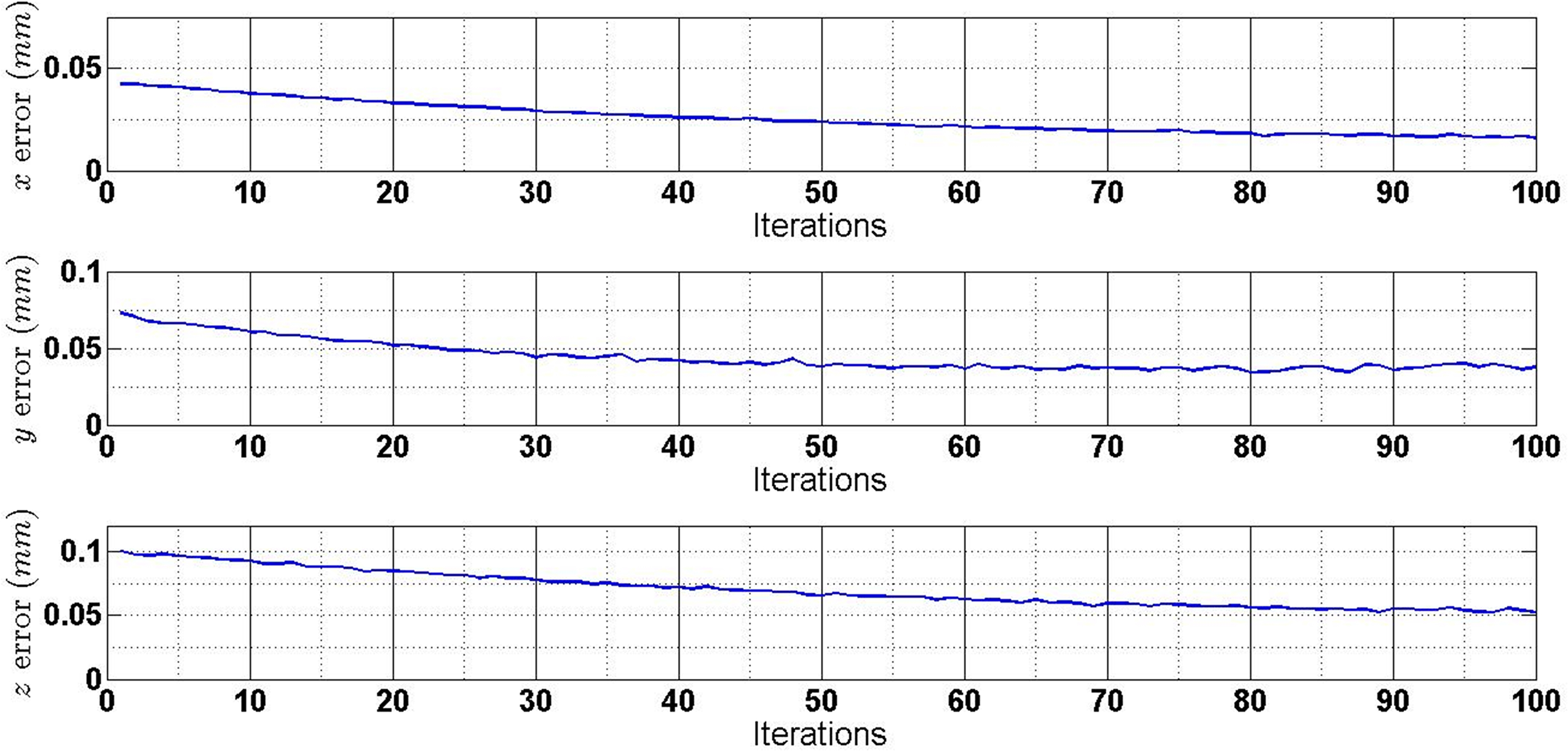
where A denotes the average error; k and n are discrete time index and maximum time index for each iteration, respectively. According to equation (21), average distance error, average position error, and average orientation error can be derived for each iteration. Figures 10 to 12 present the gradual converging process of average distance error, average position error, and average orientation error along the iteration axis. The total iterations demonstrated in these figures are 100. As shown in Figure 10, apparent decreasing trend of average distance error can be observed from around 0.14 mm to < 0.08 mm. The average position error, as shown in Figure 11, is gradually reduced to be < 0.025 mm for the x-axis, 0.05 mm for the y-axis, and the z-axis through iterations, respectively. At the same time, the average orientation error is converging continuously while average error and average error are < 0.015° and average error is < 0.01° at iteration 100. Figures 13 to 15 demonstrate the distance error, position error, and orientation error in the last iteration, that is, iteration 100. Compared Figure 7 with Figure 13, the distance error is stablely decreased along the entire time axis with the AILC scheme. Moreover, the maximum distance error with the AILC scheme is < 0.18 mm and the distance error after 5 s is keeping < 0.11 mm. Similarly, the maximum values of position error and orientation error with the AILC scheme are all lowered and they are controlled steadily to smaller value after 5 s comparing with the experimental results of the second experiment. Especially, the vibrations on both position error and orientation error with the AILC scheme are efficiently reduced so that the control process is observed to be smooth.
Average distance error of each iteration for FANUC M20iA moving forward along at speed 50 mm/s with the adaptive iterative learning control (AILC) scheme integrated.
Average position error of each iteration for FANUC M20iA moving forward along at speed 50 mm/s with the adaptive iterative learning control (AILC) scheme integrated.
Average orientation error of each iteration for FANUC M20iA moving forward along at speed 50 mm/s with the adaptive iterative learning control (AILC) scheme integrated.
Distance error of last iteration for FANUC M20iA moving forward along at speed 50 mm/s with the adaptive iterative learning control (AILC) scheme integrated.
Position error of last iteration for FANUC M20iA moving forward along at speed 50 mm/s with the adaptive iterative learning control (AILC) scheme integrated.
Orientation error of last iteration for FANUC M20iA moving forward along at speed 50 mm/s with the adaptive iterative learning control (AILC) scheme integrated.
Comparison of three experiments
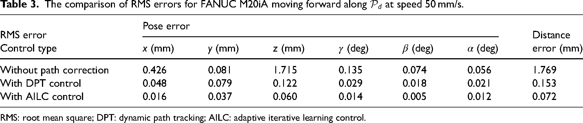
Through the comparison of some features in three aforementioned experiments, the advantages of the AILC scheme for enhancing the accuracy of FANUC M20iA can be recognized. First, the maximum pose error and distance error of the end-effector during the entire path tracking process, that is, when FANUC M20iA moves from the start point to end point of at speed 50 mm/s, are identified and presented in Table 2. It can be observed that the maximum errors of each item in each column of Table 2 are decreased significantly. Moreover, as shown in Figures 4 to 9 and Figures 13 to 15, the maximum errors definitely occur in the initial 5 s. Therefore, the comparison of the maximum errors verify that the transient performance has been significantly improved using the AILC scheme to compensate the DPT control scheme. The RMS errors of the pose and distance error from three experiments are listed in Table 3. Similar to the maximum errors in Table 2, the RMS errors for both the position and orientation errors can be significantly reduced. Table 4 gives the percentage accuracy improvement of each item based on the results demonstrated in Table 3. Most of the position errors and orientation errors can be decreased over except that the accuracy of , orientation around the z-axis of user frame, can be improved as much as , while the overall distance error can be reduced up to .
The comparison of maximum errors for FANUC M20iA moving forward along at speed 50 mm/s.
The accuracy improvement with the AILC scheme integrated superior to the DPT control scheme alone for FANUC M20iA moving forward along at speed 50 mm/s.
In this article, the AILC scheme in parallel with the DPT control scheme is proposed to enhance both transient and steady performances of dynamic path tracking for 6-DOF industrial robots with high accuracy. The AILC algorithm updates the time-varying parameters adaptively and further optimize the control signal generated by the DPT control module over successive iterations. The proposed AILC scheme is validated on a typical 6-DOF industrial robot, FANUC M20iA, through a series of experiments under different conditions (without path correction, with the DPT control scheme alone, and with the AILC scheme integrated).
Analysis of the experimental results demonstrates significant enhancement with the AILC scheme compared to the DPT control scheme alone. First, the transient control performance is improved with the AILC scheme. After certain limited iterations, high path tracking accuracy can be achieved with the maximum distance error reduced to < 0.2 mm when the TCP of the end-effector is following the desired path at speed 50 mm/s. Second, the pose accuracy can be consistently confined to < 0.1 mm for position and 0.05° for orientation after iterations. Additionally, the repetitive disturbances are mitigated within certain iterations so that the vibrations can be significantly reduced. Therefore, the AILC scheme proposed in this article is verified to be effective. Future work includes the application of the AILC scheme to the other types of industrial robots such as ABB and KUKA, as well as exploring its possibility in various industrial applications.
Footnotes
Declaration of conflicting interests
The author(s) declared no potential conflicts of interest with respect to the research, authorship, and/or publication of this article.
Funding
The author(s) received no financial support for the research, authorship, and/or publication of this article.
ORCID iD
Tingting Shu
Data Availability Statement
Data sharing not applicable to this article as no datasets were generated or analyzed during the current study.
References
1.
ArimotoS. Mathematical theory of learning with applications to robot control. Adapt Learn Syst Theory Appl1986: 379–388.
2.
BienZHuhKM. Higher-order iterative learning control algorithm. In: IEE proceedings D (Control theory and applications), volume 136. IET, pp. 105–112.
3.
BristowDATharayilMAlleyneAG. A survey of iterative learning control. IEEE Control Syst Mag2006; 26: 96–114.
4.
NgoTQTranTH. Robust adaptive iterative learning control for de-icing robot manipulator. J Rob Control (JRC)2024; 5: 746–755.
5.
ChienCJTayebiA. Further results on adaptive iterative learning control of robot manipulators. Automatica2008; 44: 830–837.
6.
XuQYWeiYSChengJ, et al. Adaptive ILC design for nonlinear discrete-time systems with randomly varying trail lengths and uncertain control directions. Int J Control Autom Syst2023; 21: 2810–2820.
7.
XuJX. A survey on iterative learning control for nonlinear systems. Int J Control2011; 84: 1275–1294.
8.
LiuKChaiYSunZ, et al. An adaptive iterative learning control approach based on disturbance estimation for manipulator system. Int J Adv Rob Syst2019; 16: 1729881419852197.
9.
LeeRSunLWangZ, et al. Adaptive iterative learning control of robot manipulators for friction compensation. IFAC-PapersOnLine2019; 52: 175–180.
10.
HuangDChenYMengD, et al. Adaptive iterative learning control for high-speed train: a multi-agent approach. IEEE Trans Syst Man Cybern Syst2019; 51: 4067–4077.
11.
ShuTGharaatySXieW, et al. Dynamic path tracking of industrial robots with high accuracy using photogrammetry sensor. IEEE ASME Trans Mechatron2018; 23: 1159–1170.
12.
TayebiAIslamS. Adaptive iterative learning control for robot manipulators: experimental results. Control Eng Pract2006; 14: 843–851.
13.
ZhangHYanQCaiJ, et al. Initial-rectification neuro-adaptive iterative learning control for robot manipulators with input deadzone and nonzero initial errors. IEEE Access2023; 11: 22441–22449.
14.
SpongMWHutchinsonSVidyasagarM. Robot modeling and control. John Wiley & Sons, 2020.
15.
XuJX. The frontiers of iterative learning control-II. Syst Control Inf2002; 46: 233–243.
16.
TayebiA. Adaptive iterative learning control for robot manipulators. Automatica2004; 40: 1195–1203.
17.
DevliegR. High-accuracy robotic drilling/milling of 737 inboard flaps. SAE Int J Aerosp2011; 4: 1373–1379.