
Abstract
The practicality allied with technological and logistical advances led customers increasingly to join e-commerce. This phenomenon was even more expanded during the COVID-19 pandemic. Because of the growing demand for logistic services, warehouses must adapt and seek faster and more efficient processes. A means to achieve that is to use mobile robots in transportation-related tasks. However, their effectiveness is only achieved if the system has an efficient work distributor. This research developed a centralized coordination architecture using the island model genetic algorithm for multi-robot logistic task allocation. The coordination receives, allocates, and monitors tasks performed by robots with different payload capacities and average speeds. The architecture was developed upon the robotic operating system. Thus, any robot with a robotic operating system-based internal system can work under the coordination of this architecture. On the results, the task scheduler, developed in previous work, had the evaluation complemented. The scheduler based on the island model genetic algorithm allocates more tasks than the standard genetic algorithm when using the same heuristic. Regarding coordination architecture, the system successfully managed a group of robots in a simulated environment. It also detected and notified failures during task execution. Therefore, this system provides a complete task scheduling, allocation, and monitoring solution.
Introduction
E-commerce is the fastest-growing retail market because of its practicality. 1 This growth has expanded even further because of the COVID-19 pandemic, as people prefer to maintain social distancing by avoiding public places and crowded areas. Consequently, the online market has become an even more attractive platform for purchasing. Additionally, the increasing use of e-commerce platforms has been boosting the growth of the logistics industry.
The logistics industry has been quickly growing,
Parallel to the growth in the logistics sector, the field of mobile robotics has been attracting significant attention from researchers in recent years. Robots with navigation skills, known as mobile robots, can replace humans in various scenarios due to their locomotion abilities. Already developed applications of mobile robots include 4 : surveillance, planetary exploration, patrolling, reconnaissance, industrial automation, museum guides, personal services, intervention in extreme environments, and transportation.
The continuous growth of e-commerce demands logistic processes that are increasingly reliable and efficient. Mobile robots emerge as an excellent solution to enhance logistic tasks and reduce costs. They are less susceptible to failures when compared to humans and can work for uninterrupted hours, limited only by their battery levels. Additionally, using environment models, mobile robots can quickly determine the location of goods and navigate autonomously to retrieve them.
A typical multi-supplier automated warehouse has product procurement, storage, and delivery stages. 5 In the procurement stage, once goods arrive in the warehouse, the order integrity and damages are verified. Also, if these products arrive on oversized pallets, they may be broken down into smaller amounts and then tagged with radio frequency identification. After identification, the products are stored in racks. These racks are distributed over extensive areas and must be handled efficiently. When a delivery order is received, the products are collected and bundled. Typically, a centralized coordinator determines the number of robot pickers and deadlines to procure products from the warehouse. Then, the goods can be packed, shipped, and the order fulfilled.
To perform pickup and delivery within an automated warehouse, the multi-robot system beyond the robots must have some coordination system. The system receives several orders and turns them into logistic tasks. Then, the tasks have to be allocated to robots capable of successfully performing them. The allocation process typically involves mechanisms of auction or optimization.
6
The multi-robot task allocation (MRTA) process can be defined as allocating
Depending on the application requirements, the MRTA can have different characteristics regarding how tasks are performed and how robots perform tasks. Gerkey and Matarić 7 proposed a taxonomy to classify MRTA problems as follows:
In single-task (ST) robots problems, each robot performs one task at a time. In contrast, multi-task (MT) robots can execute tasks simultaneously. In single-robot (SR) tasks problems, each task requires exactly one robot to execute it. However, in issues with multi-robot (MR) tasks, multiple robots may need to be applied. Instantaneous assignment (IA) means that tasks are allocated without planning for future allocations. Whereas in the time-extended assignment (TA), future allocations can be planned using information about robots, tasks, and the environment.
Several approaches can solve MRTA problems. Among them are market-based and optimization-based techniques. The traditional market-based approach is the auction, and among optimization-based approaches are genetic algorithm (GA), particle swarm optimization, and ant colony optimization.6,8 The GA is one of the most powerful meta-heuristics because it explores three key ideas: using a population of solutions as a space search, recombining two or more solutions through crossover operators to generate new and potentially better solutions, and the population’s active diversity improvement to maintain pressure in exploration.
9
In some cases, the vast search space requires additional concepts to enhance solution diversity and, consequently, exploration effectiveness. The island model genetic algorithm (IMGA) is an example. In this GA’s improvement, islands with their population and genetic operators (e.g. crossover, mutation, and elitism) allow migration of solutions to improve the genetic variability, leading the algorithm to solve more complex problems.
The approach proposed in this article complements the work previously started by Cechinel et al. 10 and solves MRTA problems with ST robots, SR tasks, and TAs using an IMGA. The present work developed a centralized architecture to coordinate a group of robots executing logistic tasks. This architecture uses the task scheduler proposed in the previous paper, which defines the ordering of the tasks and the robot responsible for each one.
Contributions
Simple and efficient centralized coordination approach for heterogeneous mobile robots with different payloads, energy consumption, and average speed. A coordination system that schedules and allocates tasks using the system proposed by Cechinel et al.
10
which optimizes the total load transported by the team of robots and battery consumption. This is achieved while considering constraints on task deadlines, robot payload capacity, and battery level, which were previously unseen in state-of-the-art systems. Combining the coordination architecture with the scheduler guarantees robots will satisfy battery constraints and deadlines of tasks. However, unforeseen events might occur, and the proposed coordination system can detect and notify the system’s user about failures. Aggregating the coordination architecture to the scheduler allows the system to operate in an online manner, which would not be possible using only the scheduler proposed by Cechinel et al.
10
The set of features encompassed in this work contributes to dealing with complex logistic tasks more efficiently and reliably.
Related work
Developing a MR system includes modeling robots, tasks, and the environment. Robots and the coordination system use these models to exchange information to minimize task execution costs and fulfill constraints. Following are described issues that authors consider in their approaches regarding models of robots, tasks, cost function, and environment.
In robot modeling, task allocation parameters are utilized to predict task feasibility further than control and cinematic issues. In some approaches, speed can be constant during navigation,11,12 but others can use current and expected speed combined with position. 13 The battery consumption must have constraints once each task must be performed by a robot with enough battery to complete it.14,15,11 A discharge factor is normally employed based on the distance or time to estimate the battery consumption. 11 Also, the system could use multiple discharge factors depending on status such as waiting, navigation (without payload), and task execution. 13 Additionally, a minimum energy threshold can be defined. Thus, when a robot finishes a task, it goes to a recharging station if its battery level reaches the threshold. 15
Logistic tasks can be modeled as simple pickup and delivery16,12 or be composed of multiple locations. 15 In some scenarios, it would be interesting to have deadlines to complete tasks 11 or constrain the payload loading time. 12 Besides that, the time and energy required to complete a task can be estimated and measured during execution. 13 Thus, the system self-evaluates and improves its predictions. When the multi-robot system has robots with different payload sizes, it is important to represent the minimum payload required to perform the task. 12
When using AMRs, a MR logistic system can adopt grid maps, a widespread technique, as environment representation,16,15,11,17 but reinforcement learning is an alternative if it is impossible to get a priori map. Thus, the robot can learn the paths on-demand while navigating the environment. 17 Besides that, the system must store coordinates of locations such as product racks, packing stations, and recharge stations to compose tasks.16,15,11,12 Some environments will have shapes more complex than others. A complexity coefficient of the environment can be applied to estimate battery consumption more precisely. 15
The fitness function for GAs, or the bid for auctions, represents the cost to perform a task. The cost representation may be simple relations of distances18,16,19 or multi-criteria considering variables such as time, distance, energy, and resources needed to accomplish a task.14,13 Besides that, the system may aim to minimize battery consumption globally and for each robot. 15 In addition, besides minimizing the cost related to task execution, the system can perform work balancing between robots.17,20 Finally, when humans work together with robots, performing similar tasks, it is interesting that robots perform tasks with heavier payloads, leaving lighter tasks to humans. 12
Several approaches have been proposed for MR logistic task allocation in the last few years. However, two techniques stand out as primary choices among researchers, the GA14,18,16,15,17 and auction.13,19,17 Other techniques, such as constraint programming 11 and simulated annealing, 12 also were used for the same porpoise. It is worth highlighting a diversified set of approaches to MR task allocation. Rossi et al. 21 presented a list of algorithms used for this purpose, such as artificial potential functions, state machines, behavior composition, and density-based control, among other centralized and decentralized optimization algorithms.
Badreldin et al. 6 conducted a comparative analysis between marked-based and optimization-based approaches in task allocation. Considering the comparison between the auction and GA approaches, the study results revealed the GA approach exhibited superior scalability compared to the auction approach. However, the auction approach showed a higher capability in assigning tasks to robots based on their specialized skills or capabilities. In task allocation scenarios with strict deadlines, both techniques yielded similar outcomes. Lastly, when the parameters of tasks or robots were subject to stringent constraints during the optimization, where parameter values and their constraints necessitated minimal or no discrepancies, the GA approach encountered challenges in achieving a solution convergence.
Multi-robotic systems must have a coordination system allowing agents to collaborate in conducting tasks or sharing resources. 22 This process allocates/schedules tasks and ensures that each robot executes them safely. Coordinating multi-robotic systems has several challenges, such as operating in dynamic and unpredictable environments, inconsistent information, unreliable and limited communication, human interaction, and system component failures. 23 The coordination system usually adopts a centralized or distributed architecture.
The centralized approach uses a single agent to coordinate the robot team. The central agent receives the tasks, requests information from the robots and the environment, and then determines how to distribute the tasks and monitor their execution. This agent can obtain optimal or close to optimal task allocation/scheduling results using all available information about agents, environment, and tasks. However, the system has a central control module, and its failure might lead to global failure. The system can be inefficient for large groups of robots because of the high demand for communication and the difficulty in detecting environmental changes. Therefore, this approach best manages small/medium groups of robots and environments where global information is easily collected.
Distributed coordination systems are fast, flexible to change, and robust to failure. However, agents only have local information about the environment and other agents. Therefore, the system might obtain suboptimal solutions that need to meet optimization requirements. Rarely do applications that use this approach deal with complex tasks or efficiency requirements. However, these approaches can select the robot most able to perform a task easily. In this approach, agents communicate with each other and, based on their local knowledge, determine which task or tasks each one will perform.
Highlights on similarities and differences
Regarding robot modeling, we adopted constant average speed during navigation. However, our method updates the robot’s average speed according to the time spent during task execution. We also considered the battery constraints, thus ensuring that each task must be performed by a robot with enough battery to complete it. Our system computes battery discharge considering the time spent on the duties. Besides that, each robot has its own battery threshold to define when recharging.
We modeled the logistic tasks as simple pickup and delivery. Although each task has its deadline, the payload loading time is defined as a robot’s constant. Our system uses parameters from the robot modeling to estimate the feasibility of the tasks, which is a common approach in the related works. Each task has its payload represented as a number of units, and a task must have at least one unit of payload.
We adopted a grid map to represent the environment for the navigation system. The map is built a priory. We also use graphs to represent it in the optimization. The graph is based on the coordinates of locations, such as product racks, packing stations, and recharge stations. However, we do not make complex distinctions between environments.
Badreldin et al. 6 found that GA is not good with task allocation optimization subject to stringent constraints. In this scenario, the space search is often vast, and the available solutions are limited. Therefore, it is necessary to enhance the GA’s exploration ability. The IMGA does that by having several islands with independent populations and genetic operators, which allows the migration of individuals among islands. This technique improves genetic variability, thus allowing the GA to deal with more stringent constraints.
The related works have shown that approaches considered payload constraints, battery level consumption, and task completion deadlines. However, the battery consumption is not directly minimized in the cost function. Typically, speed or time are minimized, and the authors claim that energy consumption also will be minimized. However, if the logistic system has robots with discharge factors significantly different, these approaches may not be ideal. It was also noticed that constraints on task deadline, robot payload capacity, and battery level are not treated together. Combining these restrictions with measuring robots’ minimum average speed allows for allocating tasks more precisely. Cechinel et al. 10 implemented a scheduler considering all these restrictions, simultaneously minimizing battery consumption and meeting task deadlines. Their scheduler also uses the IMGA, which enables efficient management of scenarios with stringent constraints. This article complements their work by proposing a centralized coordination architecture that receives, schedules, and allocates tasks using their scheduler, sends them to the robots, and monitors the execution of the tasks.
Approach
The architecture’s general operation is divided into four elements: users, database, coordinator, and robots. Following, each one of these elements will be discussed. Figure 1 shows a scheme of components that interact with each other. Each arrow means that the pointed component can receive data from the pointer one. For instance, each robot in the group of robots can read data from the database. On the other hand, the Coordinator can receive and send data to the database.

Scheme of the general functioning of the proposed architecture. Robots with green symbols are free. Robots with list symbols are busy.
The system registers and follows up on information regarding the environment, robots, and tasks in the user view. For instance, the environment has locations that can be visited, robots have average speed and their position in the environment, and tasks can be a set of locations with a status and conclusion time.
The database, as usual, stores information about all architecture components. Information regarding robots and tasks is updated on demand because the coordinator uses this information to perform the task allocation process. The coordinator and database can run on different machines without losing functionality.
The coordinator searches in the database from time to time to assign or cancel tasks. If there are tasks to be assigned, the coordinator searches for available robots. A robot is available if it is properly working and not performing a task. To do so, it sends a broadcast message to all robots in the system. After that, free robots will respond with their data that can be used in the task allocation process. This information is saved in the database by the coordinator. Then, the system tries to assign the set of tasks for the group of free robots using its task allocator. The coordinator is also responsible for checking robots’ failures. It is done by sending periodic checking messages to the robots. When the coordinator detects a failure in a robot or task, the user is notified to take contingency measures.
When a MR system robot is initialized, all its robotic operating system (ROS) packages are first started. After that, it requests current values from parameters that represent it. These parameters can change between initialization because the robot can receive an upgrade. Subsequently, the robot becomes available to perform tasks. Before performing an assigned task, the robot checks if it knows all locations in the task and, if necessary, requests the database for the missing information. During task execution, the robot shares information on which part of the task was already performed and its conclusion status. Besides that, the robot also emits alerts to failures and when it goes to charge its battery. Finally, when the robot finishes its tasks, it will notify the coordinator and navigate to its parking station.
Assumptions and limitations
Before going further with the modeling and other architecture’s components, we present the following assumptions and limitations:
The system performs tasks in an indoor environment. The environment must be previously mapped. Its locations for picking up, delivering, and recharging the battery must be identified. The robot needs only to reach a recharge station to start recharging its battery. There is an efficient communication means between the coordinator and the robots. The robots only communicate with the coordinator. They see each other as simply obstacles. The coordination system only detects failures:
The user defines what to do with tasks unscheduled during the scheduling process. If a robot fails during a pickup step, the user must decide whether the task will be reassigned in the following scheduling process. If a robot fails during a delivery step, the robot will remain stationary, and the user must physically check the robot and perform contingency actions, which include deciding whether the task will be reassigned in the following scheduling process. The scheduler needs a multicore processor to be efficient. However, having more than 36 cores might be unnecessary because the system runs parallel with a maximum of 36 islands.
Modeling
The system’s modeling is divided into environment, robots, tasks, and restrictions. Also, it presents the entity-relationship model of the database used in the system. Below is the list of symbols used in the modeling (Tables 1 to 4).
List of symbols related to environment modeling.

List of symbols related to robot modeling.

List of symbols related to task modeling.

List of symbols related to restriction.

Environment
The modeling of the environment is composed of the coordinator’s view and the robots’ view. The coordinator’s environment is a complete graph, and the robot’s environment is a grid map. A complete graph optimizes the distance calculation between locations in the task allocation process. Thus, the task allocator consults an adjacency matrix, which represents the complete graph, to get distances used to estimate time and energy spent during task execution. Figure 2 shows an example of a complete graph representing an environment. This hypothetical environment has four locations, and the distance between these locations are the numbers over the graph edges.

Example of the complete graph.
The coordinator’s view must be formalized because it is used in task allocation. The environment, or set of locations 


Because of the simplicity and effectiveness of ROS packages for mapping, localization, path-planning, and navigation, using grid maps, they were used to represent the environment in the robots. Besides that, it is necessary to estimate distances between locations during task allocation, which is done using global path-planning algorithms for grid maps. The global path planner receives the environment’s grid map as input, which has all fixed obstacles. Then, the system uses the path found by the path planner to compute the path length between each location. A path is a list of coordinates called waypoints. The system calculates the distance between each waypoint using the Pythagorean theorem. The sum of the waypoints’ distances represents the path length. Considering that the environment’s physical characteristics (e.g. shelves and parking stations) do not change over time, this process runs only once. Therefore, the database keeps the distances between each location. If a user adds a new location to the environment, it is necessary to compute the distance from each previously saved location to this location and contrariwise.
Robot
A robot Fixed attributes:
Variable attributes:


This work claims to schedule and allocate tasks to heterogeneous robots. In the present work, heterogeneous robots are robots with different maximum payload (
Some of the presented attributes deserve additional consideration. The
Task
The tasks have the same representation for both the coordinator and the robots. A task Fixed attributes:
Variable attributes:


The attribute
Restrictions
Before defining the system’s constraints, it is necessary to define the task queue and the necessary time and energy to perform a task. Equation (18) formalizes the task queue for a robot 


Database
The system’s database is an important part of the approach. The system can recover from unexpected coordination failures using the database. For instance, a coordination backup server can retrieve the system’s status before the failure. Then, it can continue following the execution of tasks and checking the robots’ status. Therefore, as the approach is centralized, the system is expected to have backup servers for coordination and a database in a real application.
Figure 3 shows the entity-relationship diagram of the system’s database. The database design considered the models of environment, tasks, and robots. Besides the system’s models, the database stores parameters used during task scheduling and coordination in the

Entity-relationship model of the system’s database.
In addition to the
The meanings of the columns in the
Coordination
The coordination system handles task scheduling, task allocation, task execution follow-up, and robot monitoring. The coordination system uses five components to perform its activities: task, robot and location controller, task scheduler, and general controller. Figure 4 shows the interconnections between internal and external coordination components.

Components of the coordination system in blue are the coordination system’s internal components.
The general controller initializes the system and allows information exchange between controllers. When the system starts, the general controller puts the threads of controllers to run. These threads check robot status, verify tasks to schedule or cancel, and follow-up on task execution.
The task controller periodically search tasks in the database to be scheduled or canceled. The efficiency of the task scheduler is affected by the number of tasks and robots in the scheduling. Therefore, there are inferior and superior limits to the number of tasks and robots in the scheduling. Thus, the scheduler works in its best range of the number of tasks and robots. The task controller maintains a list of tasks in execution for task monitoring. Each task on the list has a countdown timer that marks the expected time for the next status update. If the system receives a delayed status update, the countdown timer for the robot’s following tasks remains the same. However, in this case, the robot probably is late in its duties. Consequently, it will have less time to complete its remaining tasks. This situation might result in a future failure of one or more of the robot’s following tasks. If the coordinator does not receive a task status update before the timer stops, the coordinator sends a message to check the responsible robot. Then, if the robot does not respond, the coordinator declares failure in the task. If the failure comes from the pickup stage, the user is notified, and the task can return to the task pool. However, if the failure comes from the delivery stage, then the user is notified and must perform all needed contingency actions. Tasks can also fail in unexpected situations, such as an obstructed path or missed deadline. In these cases, the robot sends a failure notification to the coordinator.
The robot controller monitors the status of robots in the system. At the beginning of the allocation process, this controller searches for free robots. Then, the free robots answer with a message containing data used in the allocation. Besides that, the robot controller has a list containing all the system’s robots. It also has a countdown timer that marks the expected time for the next status update. An update to a robot can be a change in a task that it is performing, a request to recharge the battery or a response to the robot verification message. If the controller does not receive an update on a robot’s status, it sends a verification to the robot. Then, if it does not receive a response, the robot’s status is changed to failure. In this case, all tasks in the robot execution queue are again inserted into the allocation waiting list. The robot’s monitoring is redundancy in failure detection. While the task controller monitors each task in execution, the robot controller monitors robots and, consequently, all tasks allocated to each robot. Therefore, if the system does not receive an update from a robot, all tasks allocated to the robot are declared as failed. It also allows the detection of failures during battery recharge since the robots need to respond to periodic update requests. If a robot does not respond to them, the system detects a failure and notifies the user.
The location controller maintains the list of locations and the distance table used during the task allocation process. Locations can be removed or added at any time. Therefore, the distance table must follow these changes. Thus, when necessary, the location controller uses the global path planner to compute distances between locations.
The task scheduler is the only one that does not interact with external components. To allocate tasks, first, it receives a list of tasks to be allocated from the task controller, a list of free robots from the robot controller, and the distance table from the location controller. Then, using this information runs the optimization process using IMGA. After the optimization, the task scheduler provides a list of scheduled tasks and, eventually, a list of non-scheduled tasks. This list defines the execution order of the tasks and also the robot responsible for each one of them. The user receives notifications about non-allocated tasks to decide when to allocate them again.
Messages
The system uses three types of messages to coordinate: communication, robot data, and task queue. A communication message has type and data fields. Some messages of communication have request and response stages. Table 5 shows the data field’s communication messages and potential values.
Communication messages with type code and potential values in the data field.

Below are described the scenarios where each of the communication message types is used:
Type 0: Used by task and robot controllers to verify if a robot is still working. When a robot receives this message, it responds with the same message containing its identifier in the data field. Type 1: A message sent by the robot controller to find free robots. Free robots respond with a robot data message. Type 2: A robot sends this message to the coordinator when it needs to recharge the battery. If there are specific locations to recharge batteries, the coordinator sends a response with a location identifier. Type 3: The coordinator sends this message to the robot when a user requires to cancel a task. When the robot receives this message, it sends an echo to confirm the cancellation. Types 4 to 7: Message sent by the robot to the coordinator in the pickup step (4) and delivery step (5), when it finishes a task (6), or when it fails to execute a task (7).
When a robot receives a message of type 1 (search for free robots), if the robot is free, the robot returns information to be used during task allocation. Table 6 shows a message with robot data.
Example of the robot data message.

The last type of message is the task queue. It is a vector of tasks, where the sequence in which tasks appear on the vector is the sequence in which the robot must perform the tasks. The scheduling system can receive tasks with the same pickup and delivery location. Nothing prevents these tasks from appearing in the same task queue message. Table 7 exemplifies a task queue message.
Example of task queue message.

Internal robot system
The internal robot system allows communication with the coordinator, performing tasks, and navigation. Figure 5 shows the components of the system: navigation stack, general controller, and controllers of task, robot, and location.

Interconnection diagram of the internal robot system. In blue and gray are the parts developed in this work. In white is the robotic operating system (ROS) navigation stack.
The system uses a hybrid control paradigm, where the global path planner is deliberative and the local is reactive. Also, the system’s modules are of the functional class. Therefore, the modules have well-defined functions that combined result in more complex functionalities. Besides that, the sensors can be accessed by any system’s module using the respective sensor topic. Thus, the system has reactive communication with the environment.
The robots in the system use ROS to perform navigation. Therefore, the general controller sends destination coordinates to the ROS’s navigation stack. Then, the ROS manages path planning, motion control, and obstacle avoidance, thus ensuring safe navigation between pickup and delivery locations. ROS can use several path-planning and localization algorithms to perform the navigation. In this work, it was chosen the most popular algorithms in the ROS community. Dijkstra for global path-planning, dynamic-window approach (DWA) for local path-planning, and adaptive Monte Carlo localization (AMCL).
Since the coordinator’s task scheduler does not consider robot collision avoidance or access to shared locations, the local path planner deals indirectly with part of the coordination process. For instance, when two robots need to pass through the same corridor, their local path planner will avoid a collision. Besides that, more than one robot can try to access the same location simultaneously. In this situation, the robot that is parked will continue its loading/unloading process. The robot that wants to reach the location sees the other robot as an obstacle. Since it cannot reach the location, it will wait for the path to become clean from a safe distance configured in the DWA algorithm. This situation might cause the executing task to miss its deadline.
The task controller maintains the list of tasks to be executed. Therefore, it adds or removes tasks in the robot’s task queue
Managing robots’ proprioceptive information is the responsibility of the robot controller. It keeps updated information about the battery level, minimum average speed, current location, and the parking to recharge the battery. At the end of each task, is computed the average speed, and if necessary, the controller updates the minimum average speed. At the initialization of the system, the robot controller reads the robot’s minimum average speed, battery discharge factor, battery threshold, payload maximum loading/unloading time, and parking station from the database. Also, before performing a task, it verifies if the robot can perform it, considering the time and battery required. One may point out that the battery threshold may reach a level where the robot can’t perform any tasks. In this case, the robot will keep consuming the battery even if parked. Thus, eventually, it will reach the threshold required to recharge the battery. Note that the system can receive several chunks of tasks. Therefore, the system will probably receive a task that this particular robot can perform.
The system allows inserting and removing new locations at any time. Therefore, the distance table has to be updated along with these modifications. Constantly requiring this information in the database would be costly. Thus, the location controller updates its list of locations and distance table when the robot needs to navigate to an unknown location or parking station.
The communication between robots and coordination uses ROS topics. Also, the communication module is integrated into the general controller. Thus, when new messages arrive, the general controller interacts with the other controllers and answers the coordinator.
Following is a working overview of the internal robot system. First, the general controller receives a task queue through the communication module. Then it forwards the tasks to the task controller. Since the robot has tasks in its task queue, the general controller requests to the task controller the next task to be performed. Then, the general controller partitions the task into pickup and delivery. If a location is unknown, the location controller updates the list of locations and the distance table. After that, the robot controller checks if the robot can finish the task. Then, the general controller sends the coordinates of the pickup location to the ROS and informs the coordination about performing the task. When the robot arrives at the pickup location, the general controller notifies the coordinator and then informs it about performing the delivery. Finally, when the robot finishes the task, it notifies the coordination about the conclusion. In failure in one stage or the need to recharge the battery, the system notifies the coordinator that will take care of the contingency actions.
Task scheduler
This work uses the IMGA to allocate a task set to the system’s group of heterogeneous robots. In the traditional GA, the population of chromosomes goes through selection, crossover, and mutation, aiming to optimize a fitness function. Differently, the population is divided among islands in the IMGA. Each island implements a traditional GA with its own population. All populations have the same size and are generated randomly at the beginning of the optimization. Also, the islands can have different selection methods, crossover, and mutation. Thus, the system can benefit from the characteristics of different genetic operators during the search for a solution. The crossover operation can occur freely between individuals belonging to the same island. However, the crossover between individuals from different islands is prohibited. Also, periodically occurs individuals’ migration between islands to improve genetic variability. One benefit of the IMGA is the capacity to explore more than one region in the search space and improve genetic variability because of migration. 25 However, the migration can also impair the time performance because of its complexity.
The task scheduler used in this work was proposed by Cechinel et al. 10 This method was designed to use the IMGA to allocate tasks with deadlines in MR systems. The robots can have different payload and speed capacities. Also, the system schedules tasks optimizing robots’ energy consumption and battery level usage.
Figure 6 shows the elements of the IMGA in the approach. After receiving a list of tasks and robots from the general controller, the manager forwards this information to the islands, and randomly initializes each population. Then, the iteration loop begins with each island launched as a thread.

Scheme of the island model genetic algorithm used in this work.
Each island aims to allocate the tasks performing a traditional GA optimization in an iteration. The islands bound the optimization with sub-iterations (generations of the traditional GA), sub-iterations without improvement in the population, and a global maximum time limit. When all islands finish their execution in an iteration, the manager verifies if a result was found. Then, the manager returns the result to the general controller, which sends it to the robots. Otherwise, the best individuals migrate between islands, and a new iteration begins. Eventually, when the system reaches the maximum number of iterations or time limit, the system might not have found a result where all tasks were allocated. In this case, the manager returns the solution found to the general controller and informs the non-allocated tasks. The found solutions use the message type task queue (see Table 7). Typically, the system will generate one task queue for each robot given as input for the algorithm. The robots must perform the tasks in the sequence they appear in the solution.
Parameters related to the task scheduler such as elitism, mutation, migration, and others, are listed in the database as
For more details about chromosome representation, crossover, mutation, and migration, see Cechinel et al. 10 The paper explains the details of the implementation and justifies some choices of genetic operators.
Results and discussion
This article proposes a system that uses heterogeneous robots to perform logistic tasks. The approach uses the task scheduler proposed by Cechinel et al. 10 The previous work showed that nine islands performed better in allocating tasks than the others. Therefore, to complete the previous publication, the “Scheduler comparison” subsection compares the scheduler using 36 islands with a reduced version using just nine islands and the traditional genetic algorithm. After that, the “Simulation results” subsection evaluates the behavior of the proposed logistic system in a simulated environment. All experiments were conducted on a computer equipped with an i7-7700 CPU, 16 GB of RAM.
Scheduler comparison
This experiment aims to compare the scheduler’s performance. The experiment varied the number of tasks and robots participating in the allocation. A random group of tasks and robots were created for each repetition ensuring that the group of tasks could be performed by the robots. The experiment used the parameters obtained in the parameters’ definition experiments by Cechinel et al. 10 The parameters used are described in the sequel:
Number of repetitions: 1000; Number of iterations: 30; Number of sub-iterations: 50; Elitism: 5%; Mutation: 25%; Population on each island: 10 times the number of tasks; Migration: 5%; Stop criteria (islands): number of generations (sub-iterations), complete solution found, and 25 generations without improvement in the fitness function; Stop criteria (manager): number of iterations, complete solution found, and time performing optimization greater than Percentage of complete solutions (PCSs): the percentage of repetitions that all tasks were allocated.
Example: considering 1000 repetitions and 998 of them with all tasks scheduled. Average rate of tasks allocated (ARTA): the average rate of tasks allocated considering all repetitions.
Example: Considering two repetitions and ten tasks. In repetition one, nine tasks were scheduled. In repetition two, eight tasks were scheduled.
Average time to allocate tasks (ATATs): the average time to perform the optimization process.
We used the following performance criteria:
Figure 7 compares the percentage of complete solutions found by the three versions of the scheduler. The scheduler using 36 islands stood out as the best option. It found more complete solutions than nine islands and the traditional GA version. Therefore, the participation of all islands, which improves genetic variability, positively affects the capacity to find solutions.
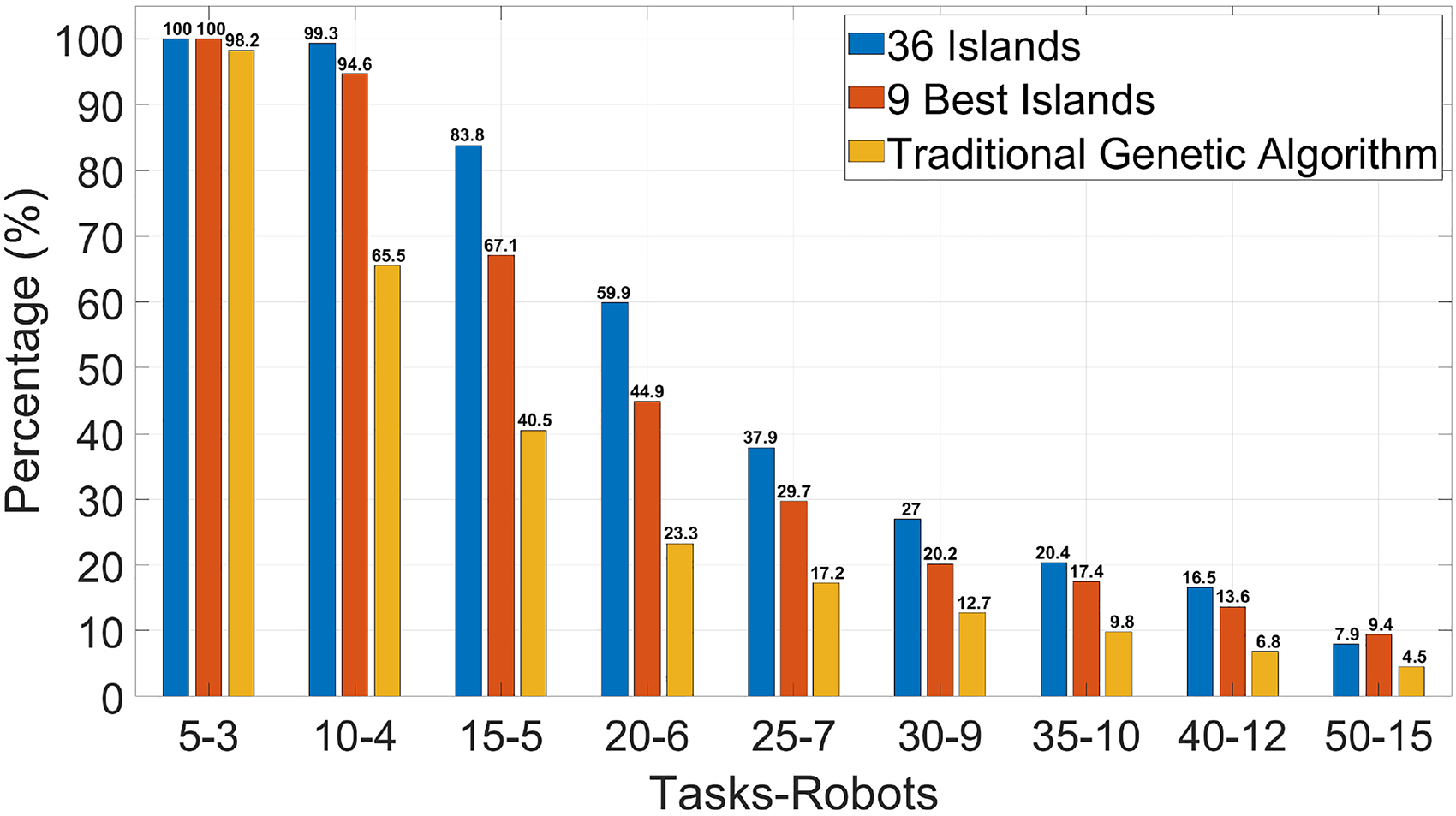
Percentage of complete solutions.
Based on Figure 8, it can be seen that all three versions have an elevated average percentage of allocated tasks. However, in practical applications, when a task scheduling fails, the task goes through one or more scheduling attempts. Also, the lower the percentage of complete solutions found, the greater the feedback of tasks to the queue of tasks waiting for allocation. Thus, even using only nine islands, the IMGA has better results than the traditional GA.

Average percentage of allocated tasks.
The last analyzed aspect, shown in Figure 9, was the average time to find a complete solution. Although the version with 36 islands finds more complete solutions and allocates more tasks on average, it also demands significantly more time. As the computer used in the experiment has only four cores, the islands could not be executed completely in parallel. However, even with this limitation, the approach using only nine islands finds solutions in less time than the traditional GA.
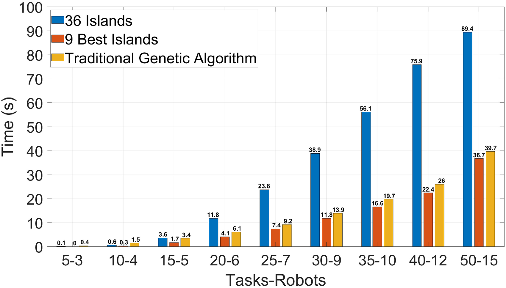
Average time to allocate tasks.
Increasing the number of cores, the IMGA with 36 islands could achieve time results similar to the one with nine islands. The experiment was conducted using a computer with four cores. Considering that all islands have the same running time and the system is not preemptive. Although this is not completely true because the system is preemptive, and the islands have slight variations in the running time, it is a fair approximation to make the following analysis. When using nine islands, the system behavior is to run four islands two times and then the remaining island. Therefore, the running time is equivalent to having three islands running in a single-core processor. When using 36 islands, the system behavior is to run four islands nine times. Therefore, it is like having nine islands running in a single-core system. Thus, if the system with 36 islands runs in 12 cores, it would be equivalent to three islands in a single core, which would probably make the running time similar to nine islands in a four-core system. In conclusion, with 12 cores, the IMGA with 36 islands could provide better solutions with running time similar to the nine islands IMGA running in a four-core machine.
Simulation results
This section explores the experiments in a simulated environment. Figure 10 shows the environment created in the gazebo simulator to evaluate the system. This environment has
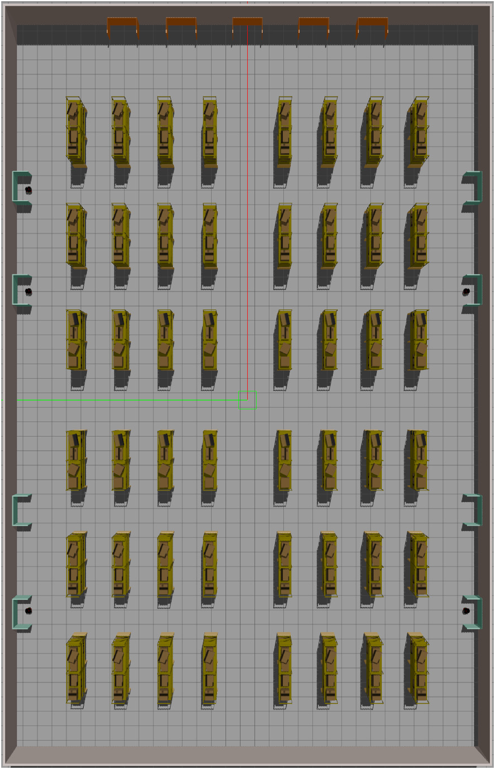
Simulation in the Gazebo simulator. In green, the parking lots. In orange are the delivery locations. In yellow are the shelves that represent pickup locations.

Grid map with locations marking. In red, the robot’s identifier is parked at that location. In green are the pickup locations. In blue are the delivery locations.
Table 8 shows parameters from the five robots used in the experiment. There are two robots with low payload capacity, two with medium, and one with high capacity. Analogously, there are two robots with low battery consumption, two with medium, and one with high battery consumption. Besides that, all robots have the same initial minimum average speed. To simplify the simulation, the robots simulate the pickup and delivery waiting for
Initial robots’ data used in the simulations.

Table 9 lists the tasks executed in the experiment. These tasks were created for the robot
List of tasks to be allocated in the simulations.

The experiment was repeated 10 times with the same groups of tasks and robots. The system returned to its initial condition, except for the minimum average speed, at each repetition. The experiment aimed to validate the system’s operation. Therefore, the system should allocate all tasks to the expected robots and coordinate the task execution while detecting failures.
All tasks were allocated in each repetition of the experiment. However, on the second and fifth repetitions, one task failed in execution, tasks 1 and 9, respectively. Both failures occurred because a delivery robot blocked the robot from trying to arrive at a pickup location. Consequently, the task being performed missed its deadline. This kind of failure happens because the robots see each other as obstacles that block the way. Figure 12 shows the effect of the failure in the second and fifth repetitions. There is an increase in total time to complete the tasks because the robot tried to perform the task for a while before informing the coordinator about the failure.

Time spent to perform all tasks.
Figure 13 shows the evolution of the minimum average speed in the repetitions. The minimum average speed is a parameter that must have its initial value cautiously defined. The robots can update the value each time they complete a task. If the new value is much smaller than the initial and other robots have values significantly bigger, the robot can be under-used in the next allocations. This situation may occur because, from the task scheduler’s perspective, this robot takes longer to complete tasks when compared to other robots, impacting its ability to meet deadlines. In the 10th iteration of the experiment, robot

Variation of minimum average speed by the robot.
Figure 14 shows the sum of the battery levels consumed to complete all tasks. Because of this, the values are above 100%. The fifth, sixth, and 10th executions had the biggest battery consumption. This result is justified in Figures 15 and 16, which shows the robots’ tasks list, their execution sequence, and the battery spent performing each one. Figure 16 can be compared with Figure 15, which graphically illustrates the design scenario. This figure can be compared with Figure 15, which shows the design scenario graphically. Robots

Total amount of battery spent.

Design scenario for robots’ tasks list, their execution sequence, and the battery spent performing each one.

Robots’ tasks list, their execution sequence, and the battery spent performing each one. Tasks shaded in red failed to be executed.
Conclusion
Mobile robotics has been an ascending research area. This area has several research fields: modeling and control, autonomous navigation, mapping, human–machine interaction, MR cooperation, intelligent decision-making systems, and task allocation/scheduling. Mobile robots can perform repetitive tasks that are sometimes unhealthy, which helps prevent human injuries. Logistic tasks are repetitive and have high aggregated value. Thus, industries have already been using this technology. However, developing a complete logistic system is complex and can involve all fields mentioned above.
This work aimed to contribute to MR task allocation and coordination for logistic systems. An IMGA was used for task scheduling in this research. The scheduler was proposed in previous work and incorporated into the coordination architecture proposed in this article. The system’s centralized coordination allows for allocating and monitoring tasks and detecting failures during task execution.
The proposed approach was evaluated regarding the scheduler and the coordination. First, the evaluation of the task scheduler by Cechinel et al. 10 was complemented. The article compared the scheduler with the traditional GA and a version using only nine islands. The scheduler using 36 islands had better results in both cases, except for the time performance. However, analyzing the results, it is possible to conclude that using a computer with a larger number of cores, the complete version probably would have the best result in all aspects.
Due to computational limitations, the system was simulated using five robots and fifteen tasks. In this scenario, the coordinator could allocate and monitor tasks and detect failures in their execution. During the experiments, two task failures failed, both related to the robots’ internal system. The robots could not arrive at the pickup location, resulting in a task failure. Once the robots see each other as obstacles, the navigation system has to generate a failure of navigation when it cannot arrive at a location. Despite these two flaws during task execution, the robots successfully performed the rest of the tasks.
Some limitations were discovered during the experiments. Therefore, we propose the following future work:
Module for robots detection and communication: Two tasks failed because the robots’ internal system detected other robots in the environment as obstacles. Therefore, a communication module between robots could be developed so that they can decide whether to wait for the other robot to leave the location or if the location is obstructed by an obstacle, causing the task to fail. Coordination decentralization: As the task allocation/scheduling system executes 36 islands in parallel, these islands could be executed on idle robots within the system. This could reduce computation time since each island would be the responsibility of a different computer, decreasing the competition for resources during optimization execution. Additionally, with a decentralized coordination system, the database could become a hybrid, partially integrated into the robots’ internal systems. This would allow statistical information about the robot and its tasks to be stored in a local database. Task monitoring could also be performed by idle robots instead of a centralized agent. Failure recovery: The system is capable of detecting failures in the execution of tasks and robots, but it is not able to recover from them, which is currently the responsibility of the system’s user. In this context, a failure recovery module can be developed to automatically reallocate failed tasks. Flow and latency evaluation: The system managed a medium-scale group of robots. However, it was not evaluated how much it demands from the network in which it is inserted. It would be interesting to define the maximum number of robots and tasks that can be managed simultaneously. These questions can be answered through network throughput and latency evaluation, combined with a benchmark evaluation of the capacity to detect task failures in situations with a large number of robots.
Additional information
The source code and experiment data of this work are available in the GitHub repository: https://github.com/alankc/IMGA-System
Footnotes
Acknowledgements
The authors are grateful for the financial support granted by CNPq to this research at the Program of Post-Graduation in Automation and Systems Engineering of the Federal University of Santa Catarina. This study was financed in part by the Coordenação de Aperfeiçoamento de Pessoal de Nível Superior—Brasil (CAPES)—Finance Code 001.
Declaration of conflicting interests
The author(s) declared no potential conflicts of interest with respect to the research, authorship and/or publication of this article.
Funding
The authors disclosed receipt of the following financial support for the research, authorship, and/or publication of this article: The authors are grateful for the financial support granted by CNPq to this research at the Program of Post-Graduation in Automation and Systems Engineering of the Federal University of Santa Catarina. This study was financed in part by the Coordenação de Aperfeiçoamento de Pessoal de Nível Superior - Brasil (CAPES) - Finance Code 001.