
Abstract
Rehabilitation for stroke patients includes periodic arm exercises, but these require assistance by caregivers at the start of the exercise, which is a burden for caregivers. In this study, we have developed a system with three reaction wheel mechanisms, which can generate not only moments in each direction but also a larger moment than the output of a single axis by interlocking the axes. In addition, by using forced oscillation control, it is possible to assist the movement of the wearer's periodic arm swing even if the weight and output moment of the reaction wheel is not large. Although a large torque of 2.65 Nm is required for the system to swing the arm, it was confirmed that the developed device can be used to increase the amplitude of arm oscillation and achieve an oscillation frequency equivalent to that of a human arm swing, even with a single reaction wheel exerting a torque of 0.4 Nm.
Introduction
Daily exercise is important not only for health but also for the effective rehabilitation of humans. Especially in rehabilitation therapy, it is effective to have a caregiver assist the patient in exercising because the patient's motor functions are impaired. However, the physical burden on the caregiver is high because the caregiver himself or herself is responsible for adjusting the patient's burden. In recent years, COVID-19 has made it difficult for elderly people who need rehabilitation to have contact with their caregivers, making daily rehabilitation difficult, which not only reduces their mobility but also adversely affects their physical and mental health. 1
Therefore, a robotic system that supports the patient during rehabilitation instead of the caregiver is desired. Many rehabilitation-assist devices have been proposed, however, a smaller, lighter, and easier-wearing device is desirable for daily use. As a rehabilitation device for improving muscle strength, there are large training devices. For example, in the system developed by Yaskawa Electric Corporation, the wearer lies on their back and fixes their legs to the device, and the robot moves the legs of the wearer to perform rehabilitation. 2 However, it is difficult to provide daily assistance to patients at home because of the large space required for installation. On the other hand, the previous exoskeleton type is based on a structure in which multiple links are connected by rotary joints and are worn across the joints. Since it is attached to multiple parts of the body, it requires a great deal of effort to attach it to patients who already have reduced mobility. In addition, since the human joint structure is not strictly a simple single-axis rotation, it places a burden on the human joints due to inconsistency with the mechanism. For joints that rotate in any direction, such as the shoulder joint, trying to support rotation in all directions makes the structure more complicated and increases the weight. In addition, it is necessary to adapt the system to each part of the body to accommodate different body structures and body sizes of individuals, which inevitably results in high costs.
To create a smaller, lighter, and easier-to-wear device, we believed that a compact and lightweight device that can be attached to only one part of the patient's body and can present forces in multiple directions, and periodically generates external forces to generate resonance phenomena to assist the patient's movement, would be suitable. We focused on the reaction wheel mechanism, which is also used in satellites,3,4 to apply external force to the patient easily and arbitrarily. The reaction wheel mechanism consists of a rotating body such as a disk and a drive source that rotates the disk. When the disk is rotated, a moment is applied from the drive source, but since the disk itself has a moment of inertia, the drive source also receives a moment in the opposite direction from the disk following the law of action-reaction. By attaching the reaction wheel to the skeleton, an arbitrary moment can be applied to the body. Although the design and control methods of the reaction wheel mechanism have been studied in many previous researches,5–7 there is no case where it has been developed as a device attached to human limbs. To generate a large moment using the reaction wheels, it is necessary to install a large and heavy motor that can generate a high output. However, for daily use in rehabilitation, the device should be lightweight and easy to attach and use so that it will not be a heavy burden for the user. Even if the force generated by the device is small, periodic motion can be caused by forced oscillation.
In this study, we developed a straightforward forced oscillation system equipped with three reaction wheel mechanisms to generate moments in any direction in three-dimensional space (Figure 1). For decreasing the torque and light-weighting, we focused on the resonant motion of the body to assist periodic movements such as arm swings. Arm swing is important for speed and stabilization during human walking8–10 and may be of therapeutic value. 11 Even more remarkable is the fact that rhythmic arm movements have been shown to enhance and shape leg muscle activity, and cyclic training of the arm improves gait, physical performance, and neurophysiological integrity after stroke.12–14 Therefore, we performed an experiment assisting arm swing like that during human walking with the developed reaction wheel.

An equipped reaction wheel module.
As a contribution of this paper, we first proposed a three-axis reaction wheel-type assist device. By mounting the reaction wheel mechanism in each of the three orthogonal directions, moment generation in all directions is possible, and the mechanism can be simplified. In addition, there is no need to change the design for each part of the skeleton. In addition, since none of the reaction wheels were designed for use on human links, we developed a reaction wheel that is lightweight and can demonstrate large swing motion. To generate moments in all directions, a reaction wheel with three axes can not only control each reaction wheel independently but can also be interlocked to generate a composite moment in a specific direction. In addition, due to the principle of the reaction wheel, there is a limit to the amount of time it can continue to exert a moment in one direction, so safety is easier to ensure than with other devices. As a more noteworthy contribution, we have proposed a method of forcing the human body links to oscillate periodically. This method enables us to assist a large amount of motion with the small weight and size of the device without complicated control if the motion is periodic. In the future, it will contribute to rehabilitation by assisting periodic arm swing.
Related studies
Rehabilitation-assist devices
Many rehabilitation-assist devices have been proposed. As a rehabilitation device for improving muscle strength, supporting and keeping the patient walking, there is a large training device that can be installed. Schmidt et al. proposed upper and lower extremity robotic device to promote motor recovery. 15 Novandy et al. developed a gait rehabilitation robot which assist the lower limb motion through arm swing based on the arm and leg coordination. 16 Veneman proposed a gait rehabilitation device for assisting motion with electromyography measurements. 17 Stauffer et al. proposed the device enables an active muscular participation of the patient in the walking reeducation process. 18 Aliakbar et al. designed a cable-driven rehabilitation system for gait training. 19 Although many devices with such a system have been proposed, it is difficult to provide daily assistance to patients at home because of the large space required for installation.
A large rehabilitation device is used for patients whose motor skills have been significantly reduced, but for patients who have recovered to some extent, many wearable exoskeletal exercise assistive devices have been proposed so that they can recover their physical functions by leading daily lives equivalent to those of healthy people. The Powered Suit HAL, developed by CYBERDYNE, is now in use at medical institutions in Japan and is also being covered by medical insurance in the world. 20 Matsuzaki et al. and Lemus et al. proposed wearable control moment gyroscopes to support human balance,21,22 however; it was focused on supporting the torso of subjects and cannot generate the moment in any direction. Afzal et al. developed a reaction wheel device to deliver balancing cues for subjects with low torque in place of assisting.23,24
Rehabilitation-assist control methods
Various rehabilitation-assist control methods also have been proposed. Several studies have increased the robot's controllability and ensured patient motion precisely. Liang et al. proposed for rehabilitation robots to achieve assist control with second-order nonsingular terminal sliding mode control and adaptive neural networks. 25 Seyfi et al. proposed a robust control of a cable-driven rehabilitation robot for precise tracking. 26
Other studies include controls that measure the patient's condition and alter the assist to enhance rehabilitation effectiveness. Riener et al. proposed robotic-aided treadmill walking training with adaptive control which increases voluntary effort of patients. 27 Zhang et al. developed performance-based assist control for robotic upper-limbs rehabilitation. 28 On the other hand, some robots have utilized a forced oscillation with elasticity for obtaining the large power for jumping. Otani et al. proposed a jumping motion generation method for a humanoid robot utilizing the leg's joint elasticity. 29 In this study, we propose a forced oscillation control to generate large motion even when the exerted torque of the assist device is small, and we believe that it would be effective to combine it with the above controls.
Methods
Modeling of a reaction wheel and interlocked reaction wheels
First, the basic model of the reaction wheel is summarized, and then a method to amplify the moment in a specific direction by interlocking two axes and three axes is proposed. In addition, a forced oscillation control is proposed to assist the periodic motion. The moment generated by a single-axis reaction wheel in the direction of rotation is shown in equation (1):


Forced oscillation method
The control objective is not to increase controllability or accuracy but to create a resonant motion to increase the swing of the arm. If the joint torque when a human performs a specific movement can be reproduced sequentially by the moment by the reaction wheel, it is possible to make the human perform any movement. On the other hand, humans often perform cyclic motions, such as walking, and we thought that we could apply a moment to assist the motion more effectively by utilizing the resonance phenomenon if the motion is cyclic, such as arm swinging during walking while moderately relaxing. However, since measuring the detailed link length and moment of inertia of the arm for each user would increase the burden of use, this study proposes a forced oscillation control that only adjusts the moment markable timing according to the oscillation angle, like the resonance when a human rides on a swing.
The angular velocity norm of the reaction wheel attitude, when the reaction wheel is swinging with the link, is maximum when the link is at the lowest position and zero when the link is at the highest angle of oscillation. It was decided to detect the oscillation state using the angular velocity information of the reaction wheel unit and drive the reaction wheel to apply the moment during the period until the link rises from the lowest point and transitions to the highest point. The speed command value is given to rotate the reaction wheel in the positive direction when the arm is moving forward and to rotate the reaction wheel in the negative direction when the arm is swinging backward. The wheel rotation speed command

Design of a wearable 3-axis reaction wheel
In this paper, to assist the arm swing with the 3-axis reaction wheel, the required specifications for realizing the arm swing during human walking are set. When walking in humans, the average maximum swing angle of the shoulder joint in arm swing was around 0.3 rad, and the arm swing cycle was around 1.0 s.
30
In addition, the shoulder joint torque
As mentioned earlier, we considered the arm swing of a person walking to be a sinusoidal wave with a period of about 1.0 s and decided to calculate the peak value of acceleration. If the arm is considered as a pendulum and the shoulder joint angle is


Arm and a reaction wheel swing model.

Numerical simulation results for arm swing with the proposed control.
Mechanical design
The reaction wheel consists of a wheel to secure the moment of inertia, a motor to rotate the wheel, and a drive circuit for the motor. Since the reaction wheel uses the inertia force when the wheel is rotated, the torque exerted by the reaction wheel is the torque exerted by the motor, and the torque executable time of the reaction wheel is the time it takes for the motor to reach the maximum rotation speed.
To achieve both lightweight and power output without reducing controllability, the following points should be considered in the reaction wheel design. First, because it is directly related to the available executable torque, the motor and the motor drive circuit should be small and light, and capable of producing a large output. Second, the larger the moment of inertia of the wheel, the longer the inertia force can be applied to the human. However, since the moment of inertia of a wheel depends greatly on its mass, simply increasing the moment of inertia increases the mass of the wheel, making it difficult to wear the device on the patient. Therefore, the wheel of reaction wheel should be designed to be lightweight and have a large moment of inertia.
A three-axis reaction wheel was designed to satisfy the required specifications. For the motor, we used EC 45 flat brushless DC motor (Maxon Inc.), which is compact and lightweight, and the motor driver circuit is EPOS4 Compact 50/8 (Maxon Inc.). To increase the moment of inertia while keeping the wheel light, the mass should be concentrated far from the axis of rotation. By considering the performance of the motor and motor driver, the required exerted torque of the single-axis reaction wheel can be calculated from equation (1), and the moment of inertia required to ensure the acceleration time can be calculated as shown in equation (15), assuming that the acceleration command value


Parameters of the ring wheel.

Figure 4 shows the photo of a three-axis reaction wheel equipped with three axes of the single-axis reaction wheel. The developed reaction wheel has a cubic shape of 141 cm. The ring wheel is connected to the D-cut motor shaft with a set collar and rotated so that the reaction torque due to rotation acts directly on the motor mount, which in turn is directly loaded on the arm. The motor mount is attached to the arm by a clamping mechanism because it must be fixed so that the reaction torque is transmitted to the arm.

Photo of the reaction wheel module. (a) Outside. (b) Inside.
The system configuration for using the 3-axis reaction wheel and the control block diagram are shown in Figures 5 and 6. The entire system consists of a motor driver to drive the reaction wheel, an incremental encoder mounted on a BLDC motor, and a reaction wheel. The entire system consists of a motor driver to drive the reaction wheel, as shown above, an incremental encoder mounted on the BLDC motor, a high-power drive power supply for the reaction wheel, an IMU (Inertia Measurement Unit) sensor (LP-RESEARCH Inc.) to measure the posture of the arm wearing the reaction wheel in absolute space, and a PC to process the data and control the reaction wheel mechanism, and a PC that processes the data and controls the reaction wheel mechanism.

Schematic view of the proposed system.

Control diagram of the proposed system.
The PC and the motor driver are connected via USB, and the ROS node of the PC sends and receives data such as control command values with a period of 11 Hz. The PC and the IMU are connected via Bluetooth, and the independent ROS node of the PC communicates attitude data with a period of 100 Hz (Figure 7). In the RW-Controller node, the Reha_Controller generates the arm swing trajectory that instructs the human, and the Motion_Controller performs the coordinate system transformation from the human coordinate system to the motor coordinate system, etc., and issues instructions to the motor. The Lps_Controller node, which is provided by the developer of each part, communicates with the IMU, and the epos_hardware node communicates with the motor driver.
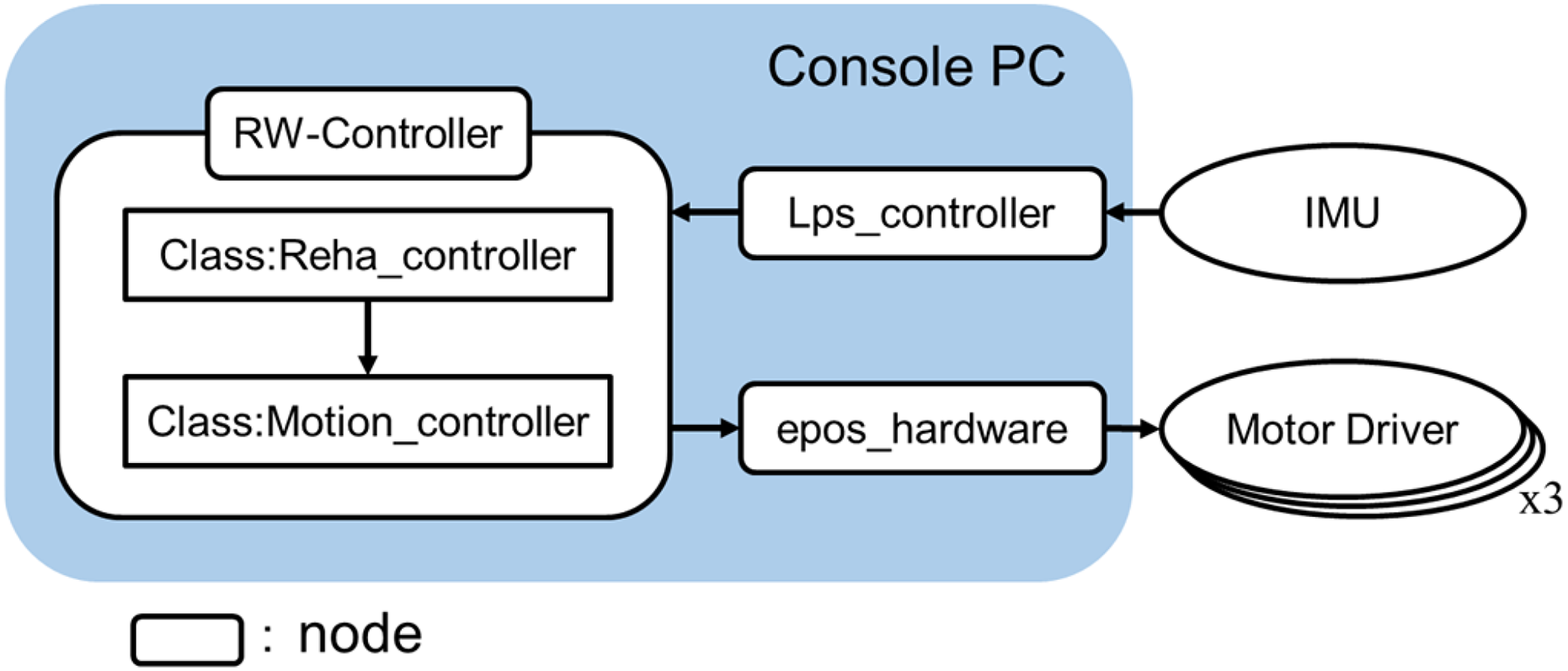
Schematic view of the ROS system.
Experiment
Evaluation of interlocked reaction wheels
We verified the output torque with interlocked reaction wheels. The developed reaction wheel device was placed on a 6-axis force/torque sensor, and moments were measured and compared when only a single reaction wheel and interlocked reaction wheels were driven.
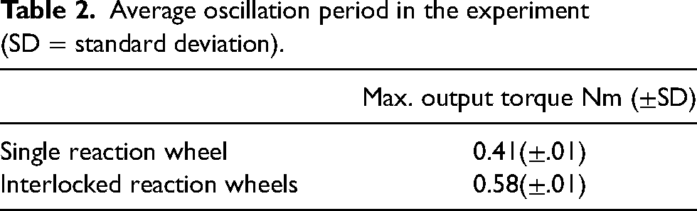
Table 2 showed the experimental results. Comparing the torque of a single reaction wheel with that of the Interlocked reaction wheels, the torque was 1.4 times higher, confirming that it can be operated as in equation (3).
Average oscillation period in the experiment (SD = standard deviation).
Forced arm swing experiment
We verified whether the proposed forced oscillation control can realize human arm swing. We attached a 3-axis reaction wheel to the upper arms of subjects (six healthy males in their 20s and three healthy females in their 20s) and asked them to lower their arms by relaxing them. After that, we instructed the participants to maintain the weakness of the entire arm as much as possible and presented the moment through forced oscillation control by the two reaction wheels. The presented torque was calculated in equation (16) using the motor current measured by the motor driver and controlled:
The photo of the experiment is shown in Figure 8, and the experimental results for each of the nine subjects are shown in Figure 9. The horizontal axis shows the time from the start of the control, and the vertical axis shows the arm swing direction posture of the reaction wheel. The results of several subjects are shown in Figure 10. The horizontal axis shows the time from the start of the control, and the vertical axis shows the arm swing and the output torque by one of two reaction wheels. The two reaction wheels each produce similar outputs of up to about 0.4 Nm each, giving a maximum combined torque of about 0.6 Nm to the swing direction. In each case, it took about 4 s to achieve the motion by the forced oscillation control, but it was possible to achieve the same level of arm swing as when walking, even if the subject was weak and only needed a force-saving assist.

Experimental photo of the forced oscillation experiment. (a) Initial condition (b) Arm oscillation.

Arm oscillation in the experiment (n = 9).
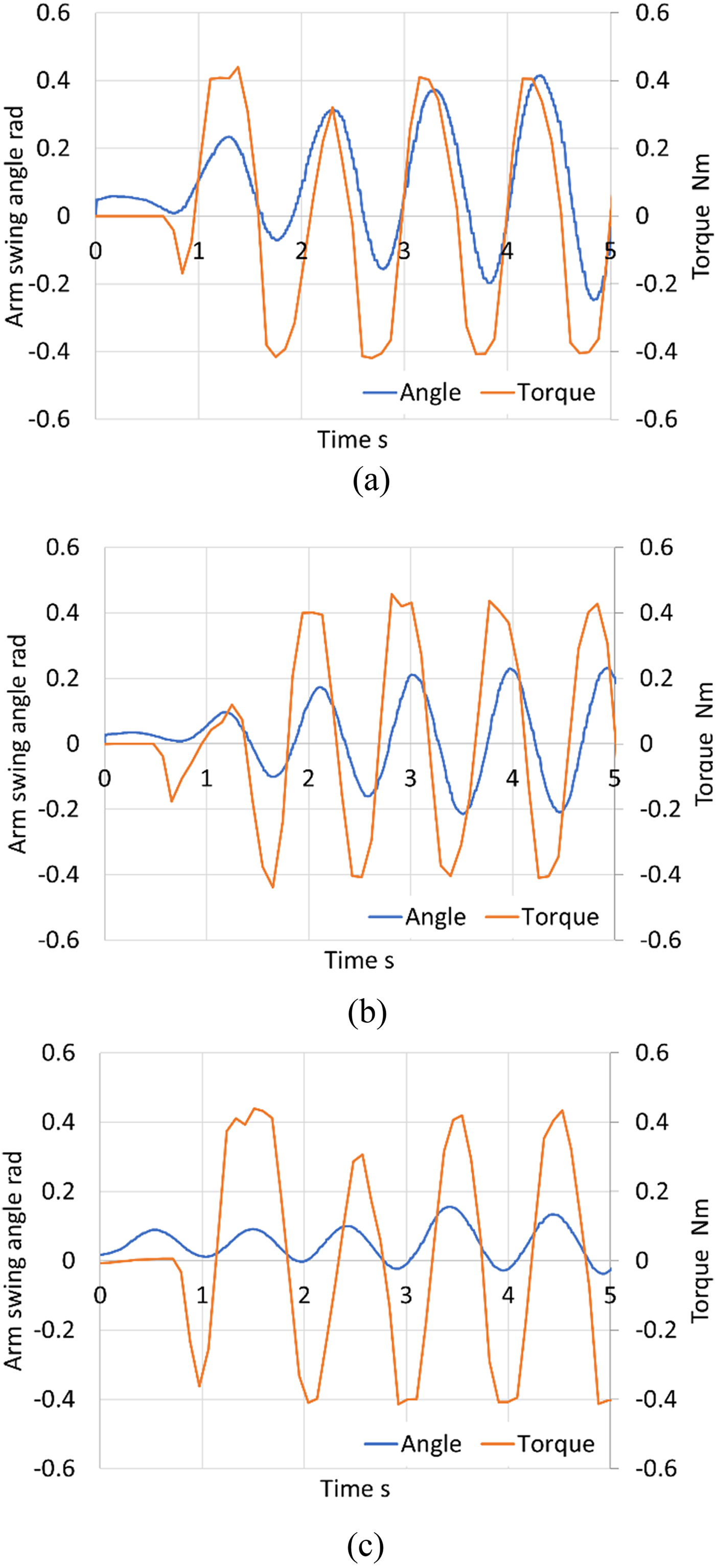
Arm oscillation applied torque. (a) Subject A. (b) Subject C. (c) Subject G.
Discussion
To solve the problem that a large torque of 1.87 Nm is required for one reaction wheel to swing the arm without using the forced oscillation control and the device becomes heavy, it was confirmed the forced arm oscillation control can be used to increase the amplitude of arm oscillation and achieve an oscillation frequency equivalent to that of a human arm swing, even with a single reaction wheel exerting a torque of 0.4 Nm. The average oscillation period and RMSE of arm swing angle between the simulation result with 0.6 Nm torque in Figure 3 and in four oscillations for each subject are shown in Table 3. Since the average period of oscillation was about the same as that of human walking, it was confirmed that the same arm swing was achieved not only in amplitude but also in period. On the other hand, the RMSE between the experimental and simulation results for the arm swing angle is a little large, but as can be seen in Figure 9, the phase shift between the experimental and simulated results increases little by little. It is thought that there was some torque exerted by the subject that was not included in the simulation. Since the degree of arm relaxation was not measured quantitatively, there is still a possibility that the subjects did not fully relax and rather lightly swung their arms following the oscillation. In particular, the time required for the amplitude to increase was shorter for subject A than for the other subjects. However, since all the subjects showed the almost same period of arm swinging with gradually increasing amplitude, and the experimental results were like the simulation results shown in Figure 3, it was considered that the system had the effect of assisting exercise rehabilitation, which was its original purpose. In the future, we will verify the relationship between the intensity of the assist and the exercise together with the measurement of the exerted muscle strength using muscle potential measurement. Moreover, to effectively generate resonance, it may be effective to incorporate fractional order control,33,34 which is often used in systems that include oscillation.
Average oscillation period in the experiment (oscillation numbers = 4, SD = standard deviation).

In this article, we proposed the configuration of a 3-axis reaction wheel and summarized the components as a device. If the motion can be limited, it is possible to use a single-axis reaction wheel to reduce the weight. However, in any case, a high-powered power source must be considered for use with a sufficient driving force, and a battery that can be carried on the wearer's back is necessary for mobility. As for the reaction wheel itself, it is possible to mount a higher-powered motor on the outside of the reaction wheel, and the reaction wheel can be made even lighter by using wires or a flexible shaft to transmit the power.
Conclusion
In this article, we proposed the configuration of a 3-axis reaction wheel and the forced oscillation control to assist periodic arm swing. Cyclic arm movement training improves gait, physical performance, and neurophysiological integrity after stroke. The merits of this study are the forced oscillation control and the interlocking reaction wheels that achieve larger motion with a smaller- and lighter-weight motor than previous systems. In fact, a torque of 1.87 Nm is required for arm swinging without utilizing resonance, but with the forced oscillation control, arm swinging could be achieved after several oscillations even with a torque of 0.6 Nm. On the other hand, as a limitation of this study, it is necessary to improve the output performance of the device itself and to design and verify the training operation method for practical use. In particular, to improve performance, it is desirable to study not only design issues such as increasing the power supply output and changing the motor driver to achieve higher output but also highly efficient arm oscillation control using electromyographic feedback or fractional order control.
In the future, we will proceed to verify the effectiveness of rehabilitation using this device. For further performance improvement, a high-powered power source must be used for a higher driving force.
Footnotes
Acknowledgments
This study was conducted with the support of the Research Institute for Science and Engineering, Waseda University; the Human Performance Laboratory, Waseda University; the Future Robotics Organization, Waseda University; and as part of the humanoid project at the Humanoid Robotics Institute, Waseda University. It was also financially supported in part by the JSPS KAKENHI Grant No. 21K17832. Further, 3DCAD software SolidWorks was provided by SolidWorks Japan K.K.; The authors thank all of these for the financial and technical support provided.
Data availability
All data analyzed during this study are included in this published article. The specific datasets are available from the corresponding author on request.
Declaration of conflicting interests
The author(s) declared no potential conflicts of interest with respect to the research, authorship, and/or publication of this article.
Funding
The author(s) disclosed receipt of the following financial support for the research, authorship, and/or publication of this article: This work was supported by the Japan Society for the Promotion of Science, (grant number 21K17832).