
Abstract
Aiming at the application of robots in service, medical treatment, rehabilitation, and other fields, a humanoid cable-driven hybrid robot by imitating the structure of human arm is designed in this article. The robot is composed of a cable–spool–pulley system, series mechanism, and coaxial spherical parallel mechanism, which can achieve six degrees of freedom movement in space. A challenge with cable driving is that the movement of the rear end joints (such as pitch and roll) can alter the length or tension of the cable driven by the frontend joints, resulting in joint coupling. This interference can lead to a decrease in the motion accuracy of the robotic arm. In addition, it also affects the durability of cables or mechanical components such as bearings and pulleys. Considering the joint motion coupling phenomenon caused by the cable-driven, the decoupling method is proposed, and the kinematic model of the robot is established. To solve the nonlinear coupling characteristics and the uncertainty of the dynamics parameters, a controller is proposed for the humanoid cable-driven hybrid robot, combining proportional-integral-derivative (PID) control based on decoupling method (DC-PID) and the double delay deep deterministic policy gradient (TD3) deep reinforcement learning algorithm. The trajectory tracking of the end-effector position and orientation are controlled by using DC-PID and TD3. And the simulation results show that the proposed control method has good trajectory tracking and convergence performance according to trajectory tracking error and training reward. Finally, the humanoid cable-driven hybrid robot prototype is developed. The experimental results of coupling compensation show that the average maximum error of the joint is reduced by 77.58% after considering the coupling compensation of the joint. The results of the controller validation experiments show that the DC-PID controller reduces the maximum error in each axis by 11.54%, 35.29%, and 40.16%, respectively, compared to the open-loop experiments.
Introduction
With the deepening of robot application, the traditional rigid robot gradually shows disadvantages due to the problems of low load–weight ratio, low energy efficiency, lack of flexibility, and so on when it comes to the requirements of medical treatment, rehabilitation, human–machine cooperation, and other fields. Therefore, it is necessary to innovate the robot structure. Cable-driven 1,2 is a robot drive method proposed in the late 1980s. Flexible cable (such as wire rope, and so on) has good flexibility and elastic buffer characteristics, and cable-driven can also provide a certain degree of feedback, allowing individuals to sense changes in the external environment during the interaction with the machine, thereby adjusting their movements and posture more flexibly and improving the safety and efficiency of human–computer interaction. 3 –5 Compared with the traditional connecting rod hinge drive, the motor and the robot joint rely on the flexible cable transmission force and torque, break through the hinge angle and telescopic length limit, so the motor and speed reducer can be installed outside the robot body, the inertia of moving parts can be greatly reduced and improve the dynamics performance and response speed of the motor and the driver. The end-effector is allowed to obtain higher speed and acceleration, 6,7 which can achieve higher working efficiency than the traditional rigid robot.
The cable-driven robot is complementary to the traditional rigid robot, which expands the application prospect of the robot in service, 8,9 medical rehabilitation, 10 –12 surgical treatment, 13 and so on. Lalithkumar 14 et al. investigated a flexible cable-driven single-hole surgical robot with a spring backbones and tubular luminal restraint; used a master-slave structure with tendon actuation to achieve robot function; and improved tendon routing, anchoring, and fixation based on the principle of cable actuation for the spring skeleton bending method. Li 15 et al. studied a cable–pulley transmission mechanism for surgical robot with back-drivable capability. Low friction and back-drivable, compared to conventional non-back-drivable mechanisms based on gear coupling, is achieved by means of differential cable driven method. KoreaTech introduced LIMS2-AMBIDEX, 16 a seven-degrees of freedom (7-DOF) flexible cable-driven robot in 2018. The part below the shoulder joint is only 2.63 kg, and all the driving motors are arranged at the shoulder joint, which greatly reduces the robot’s self-weight. Differently from the traditional rope-driven shaft rotation to achieve movement, the wrist joint uses the retracting and releasing of the rope to realize the working space of a half sphere in the space, which highly simulates the working range of the human wrist. Kim et al. 17 introduced a novel bio-inspired cable-driven knee orthosis, with the bio-inspired rigid joint structure, which is kinematically identical to the human knee joint shape on the medial and lateral sides, and it is possible to prevent the occurrence of abnormal load due to the misalignment as well as reducing the load transmitted through the musculoskeletal system.
In the research field of cable-driven or flexible robotic arm control schemes, various innovative methods and technologies have emerged. Some studies focus on optimizing the motion trajectory planning of cable-driven robots to enhance their motion efficiency and accuracy. Peng et al. 18 proposed a trajectory tracking framework for cable-driven robotic arms by combining dynamic feedforward control and proportional-derivative (PD) control, with active cable tension and end effector pose as optimization indicators. Xie et al. 19 presented a robust synchronous control scheme in the cable length space to achieve high-precision trajectory tracking of cable-driven robotic arms. Li et al. 20 proposed a method based on fuzzy control to adjust the stiffness coefficient of the robotic arm to enhance the robustness of cable-driven robotic arms. Fareh et al. 21 introduced an advanced robust disturbance rejection control for flexible link manipulators to track desired trajectories in joint space and minimize link vibrations.
With the continuous development of artificial intelligence technology, autonomous learning algorithms based on deep learning and reinforcement learning have been applied more and more widely. Among them, deep reinforcement learning (DRL) 22,23 provides a way to solve the trajectory planning problem of high-dimensional continuous state and motion space. In recent years, many researchers have used DRL algorithm to solve the problem of robot trajectory tracking control and path planning in complex environment. 24 –26 Zhao et al. 27 studied robot trajectory tracking control based on reinforcement learning and proposed a model based actor-critic learning, which effectively improved robot trajectory tracking accuracy and solved the problem of a long learning period of control strategy. In addition, Zhao et al. 28 also studied the robot impedance control based on reinforcement learning, which can effectively improve the stability of robot interaction with the environment. Zhong et al. 29 proposed a path planner for welding manipulator based on DRL, introducing an inverse kinematics module to provide prior knowledge for improving learning efficiency, while designing a gain module to avoid local optimal strategies. Wagaa et al. 30 developed different deep learning networks for solving the inverse kinematics problem of 6-DOF robotic manipulators. Zheng et al. 31 solved the problem of low convergence of action selection strategy and reward function at two levels to solve the difficulty of optimal strategy in trajectory planning when DRL is applied, designed a dynamic action selection strategy, and proposed a combined reward function combining artificial potential field method and time–energy function. Sun et al. 32 proposed a novel motion planning method based on DRL, called reconfigurable structure of deep deterministic policy gradient for mobile robots, which can adaptively change the network structure.
Based on the design concept of man–machine cooperation, high speed, and low inertia, this article designed a humanoid cable-driven hybrid robot (CDHR) driven by flexible cable with 6-DOFs to simulate the structure of human arm. Aiming at joint coupling phenomenon, decoupling method is proposed, and kinematic model is established to realize high-precision motion simulation. Due to the nonlinear coupling characteristics and the uncertainty of the dynamics parameters, combined with its hybrid characteristics, a controller is realized by combining DC-PID control and TD3 DRL, and the position tracking and orientation training simulation are carried out. Finally, the effectiveness of the decoupling method and the controller are verified by the trajectory tracking experiment.
Mechanical design and modeling
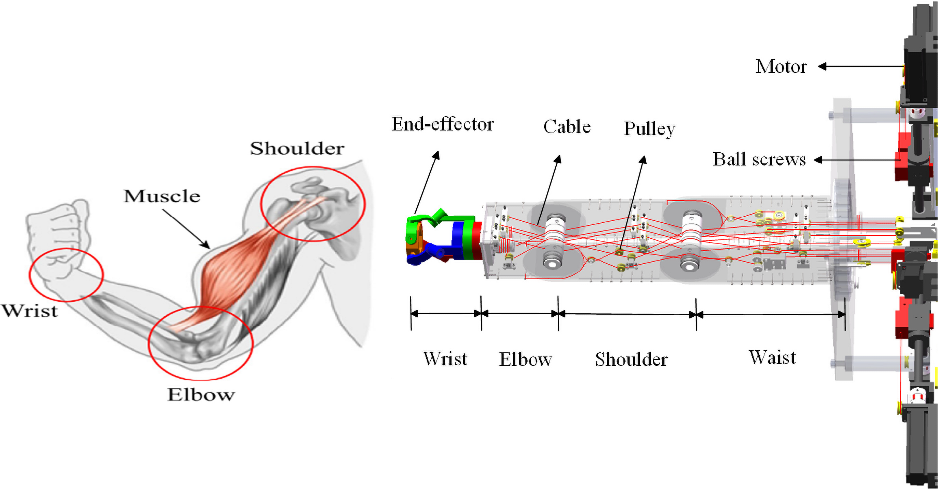
The novel humanoid CDHR designed in this article mimics the human arm, which is mainly composed of three parts: a cable–spool–pulley system, a series mechanism, and a coaxial spherical parallel mechanism (SPM). The overall structure is a humanoid arm with a spherical wrist, and the wrist has the full DOF of roll, pitch, and yaw. As shown in Figure 1 for three-dimensional (3D) model of the humanoid CDHR, the robot has the advantages of low self-weight, small moment of inertia, and good dynamics performance.
A three-dimensional model of a humanoid CDHR. CDHR: cable-driven hybrid robot.
To improve the safety of human–robot interaction, the robot is cable-driven, which guides the ropes through the guide grooves and guide wheels inside the robot, and realizes the coordinated expansion and retraction of 12 cables by controlling six groups of cable-driven units. Each pair of flexible cables is connected through a slider on the ball screw to achieve bidirectional motion of the joints. The internal wiring of the robot is shown in Figures 2 and 3. Figure 2 shows the routing of the cables that drive the parallel mechanism of the robotic arm. Considering that it would be difficult to discern the position and function of each cable if all the cable routings were displayed in a single image, we divided the cable routings based on different driving joints into subfigures (a), (b), (c), and (d) and differentiated them using different colors. The red, yellow, and blue cables in Figure 2 control the rotation of the base joints of the corresponding red, green, and blue links shown on the right side of Figure 9.
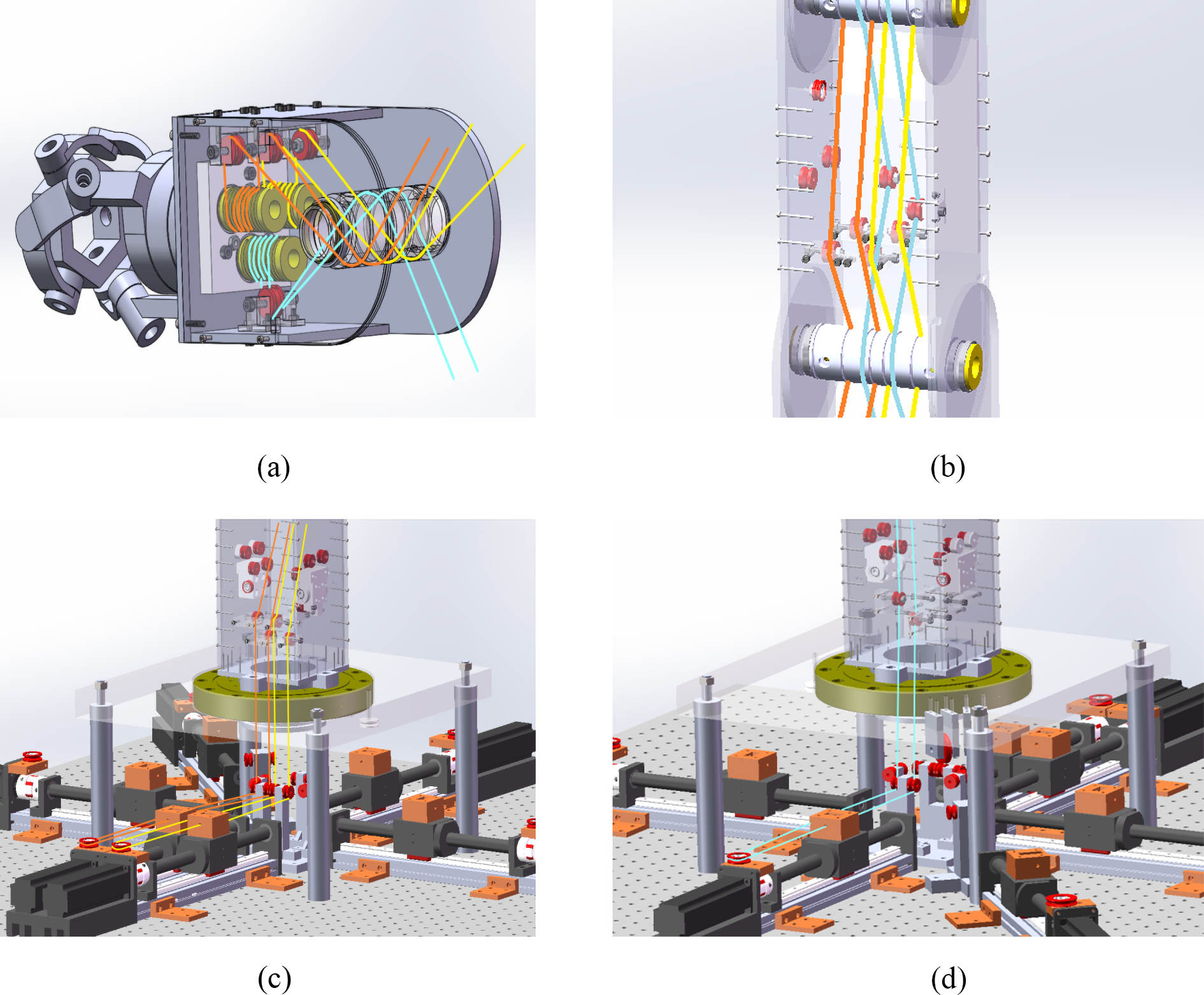
Overall wiring diagram of the parallel mechanism driving flexible cables.

Overall wiring diagram of the series mechanism driving the flexible cable.
Figure 3 shows the routing of the cables driving the serial mechanism of the robotic arm. Similarly, we have divided the cable routings based on different driving joints into subfigures (a), (b), (c), and (d) and differentiated them using different colors. The green and pink cables in Figure 3(a) and (b) collectively control the rotation of the link labeled as ③ in Figure 3(a), and the blue and purple cables in Figure 3(c) and 2(d) collectively control the rotation of the link labeled as ② in Figure 3(a).
Simscape is a physical modeling toolbox integrated under Simulink, which can imitate real objects for modeling and simulation, and it is widely used in the simulation of physics, mechanical engineering, and other fields. 33 The humanoid CDHR designed in this article is physically modeled in Simscape. Through the coordinate transformation and motion relationship between various parts of the robot, the simulation model as shown in Figure 4 is finally constructed. It is worth noting that in the simulation model in Figure 4, to improve the simulation efficiency, the linear guide module underneath the base of the robotic arm on the right side of the 3D model in Figure 1 has been simplified and replaced with a cable reel, as shown in Figure 4. The winding and unwinding of the driving cable is controlled by controlling the rotation of the cable reel.

Simscape system diagram.
The simulation model in Figure 4 is divided into two modules: the kinematics solving module and the manipulator simulation module. The kinematics solving module consists of three main components: trajectory planning, inverse kinematics solving, and decoupling. Meanwhile, the manipulator simulation module includes a cable–spool–pulley module and an environment configuration module. In Figure 4, t represents the current simulation running time, while x, y, and z represent the end position of the manipulator, and
The 3-DOF coaxial SPM 34,35 is used as the wrist joint of the robot. The paragraph describes the kinematic model of a 3-DOF coaxial spherical parallel wrist at the end of a robotic arm, as shown in Figure 5. The kinematic chain 1, kinematic chain 2, and kinematic chain 3 in Figure 5 correspond to the red, green, and blue link configurations in Figure 9. The moving platform in Figure 5 corresponds to the platform numbered 3 in Figure 8. Each of the three kinematic chains in Figure 5 is mainly composed of a base, a proximal end, a distal end, and a platform, and the base joints of the three chains are coaxial. Because the arc-shaped connecting cable has the property of bending in different planes, the structure ensures that the beams of each rotating pair on the three branch chains intersect at the same point (the center of the sphere), and the movement area of the platform will be a sphere. This configuration can effectively control the motion orientation of the moving platform, with strong bearing performance, high control accuracy, fast feedback speed, compact structure, and no negative motion pairs. Physical modeling function of cable is also provided in Mutibody, and parts of cable are constructed using Belt-cable spool, Pulley, and Belt-cable properties modules. As shown in Figure 6, taking the cable-driven unit of the forearm joint as an example, parameters such as the initial angle and winding radius of the flexible cable are set through the Belt-cable core (No.① in Figure 6) and the Pulley module (No.② in Figure 6). The Belt-cable property module (No.③ in Figure 6) is used to modify the inherent properties of the cable.
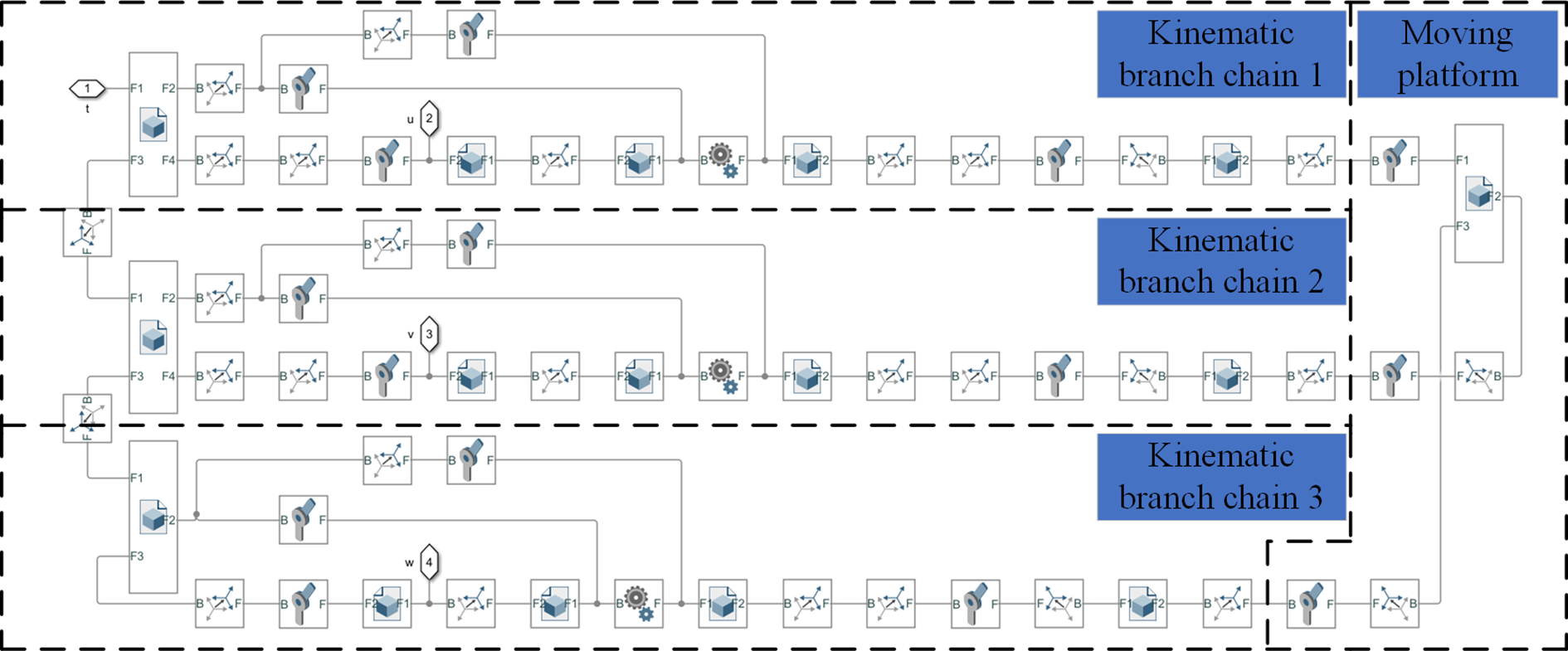
Three rotary joints (3-RRR) coaxial spherical parallel mechanism.
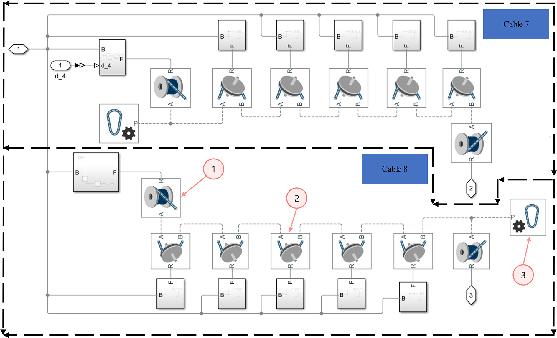
Cable-driven unit of forearm joint.
Kinematics analysis and simulation
The kinematic analysis of the humanoid CDHR is carried out. The schematic diagram of the robot mechanism is shown in Figure 7. In the figure, joint 1 is the waist rotary joint, joint 2 is the big arm pitching joint, joint 3 is the forearm pitching joint, and joints 4, 5, and 6 are the coaxial parallel joints. li (i = 1, 2, 3) is the rod length of the mechanical arm. The movements of each joint are described mainly in terms of the base coordinate system U and the end-effector coordinate system T . According to the robot configuration, the position and orientation of the end-effector of the robot are determined by the series mechanism and the coaxial SPM, respectively. Therefore, the kinematic model of the two parts is established respectively, and the overall kinematic model is obtained.
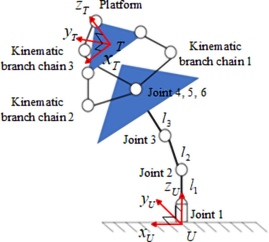
Schematic diagram of robot mechanism.
Kinematics analysis of 3-DOF series mechanism
The kinematic model of 3-DOF series mechanism is established by using D-H parameter method. Establish the coordinate system for the robotic arm as depicted in Figure 8, and utilize this established coordinate system Establish the coordinate system for the robotic arm as depicted in Figure 8, and utilize this established coordinate system to derive the DH parameter table shown in Table 1. In the table, d 1, a 2, and a 3 correspond to the lengths of l 1, l 2, and l 3 in Figure 7, respectively.

D-H coordinate system of series mechanism.
D-H parameters of tandem mechanism.

Through D-H coordinate transformation, the calculation formula of transformation matrix of 3-DOF series mechanism can be written out

Then the forward kinematic transformation matrix is

where
In engineering application, inverse kinematics is the key step to realize the robot motion control. The commonly used methods include numerical method, analytical method, and geometric method. In this article, the analytical method is used to solve the angle value of each joint of the robot.
It should be noted that in the process of solving the inverse kinematics of the robotic arm, the three joint angles
From the fourth column of equation (2), we can know the position of the end-effector in space

Firstly, the angle of joint 3 is solved

It is easy to obtain from the above formula


thus

According to the sign of s3, two solutions are given

Then find the angle of joint 2. In equation (4), s
1, c
1 is eliminated from


According to equations (3)
to (8), we can know that the angle of joint 3 has two solutions, and the angle of joint 2 has four values of four-quadrant arctangent according to equations (9) and (10). Therefore, theoretically, there are eight combinations of the forms of solutions, but excluding the four groups of solutions that do not conform to

Finally, the angle of joint 1 is solved, which is obtained from equation (3)

Permuting the joint angles, according to equations (8), (11), and (12), it can be seen that there are four groups of inverse solutions for the 3-DOF series mechanism

Kinematics analysis of 3-DOF coaxial SPM
As shown in Figure 9, No.① represents the proximal link, No.② represents the distal link, and No.③ represents the mobile platform. Different from the general spherical three rotary joints (3-RRR) parallel mechanism,
36,37
the rotation axis of the proximal member of the 3-DOF SPM designed in this article is defined as the vertical direction (

Diagram of parallel mechanism.
From the above definition, we can write the unit vector ui for the first joint of the three motion chains

The expression of unit vector wi of the intermediate joint is
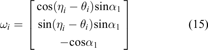
where
The unit vector vi of the third joint represents the direction of the moving platform, and there are constraints with the other two unit vectors. According to the geometric constraints, the following equation can be obtained

where
Equation (16) gives nine equations, which are solved by numerical method and x
0 is defined as shown in equation (19). The SPM designed in this article is l-l-l assembly mode, all the distal branch links are located on the left side of their central plane of symmetry, and vi
always points to the positive direction of the branch chain rotation motion. So the initial vector x
0 is an instance of the unit vector wi
rotating in the positive direction in the same direction as the z-axis. Assuming that the unit vector wi
rotates

where
Substituting the value of

where
The initial value is obtained as

According to the above equation, the direction vector vi of the moving platform can be obtained

To facilitate the observation of orientation changes of the moving platform, the normal vector n of the moving platform is used to represent
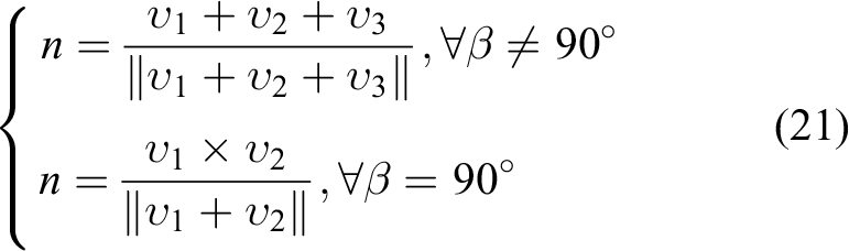
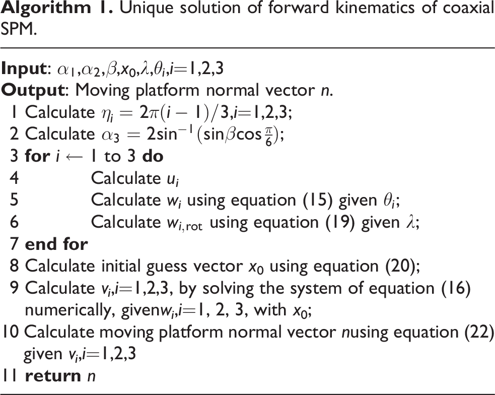
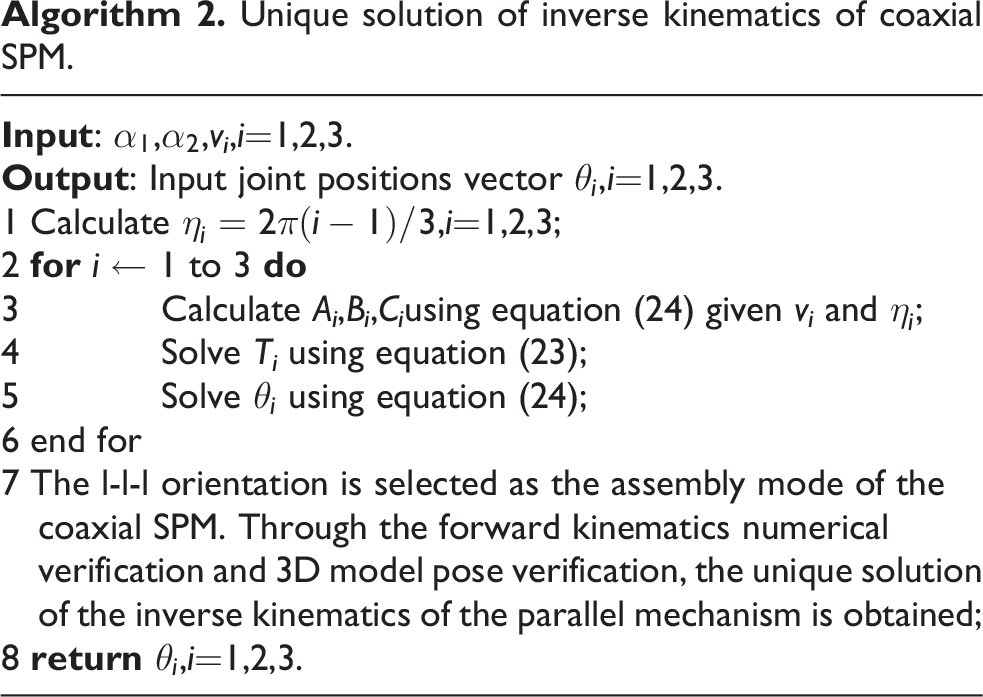
Thus, the unique solution of the corresponding forward kinematics problem in l-l-l assembly mode can be obtained. Its specific solution process is shown in the algorithm below.
The inverse kinematics of the coaxial SPM is solved below. Given the direction vi
, i = 1, 2, 3 of the moving platform, the angle
According to the first equation of equation (16), the following expression can be obtained

Among them

Unique solution of forward kinematics of coaxial SPM.
According to equations (23) and (24), the angle

Orientations of eight groups inverse kinematics solutions of SPM. SPM: spherical parallel mechanism.
Unique solution of inverse kinematics of coaxial SPM.
Kinematic coupling analysis of joints
The cable-driven joint robot uses the flexible cable as the driving medium. On the one hand, the load–deadweight ratio of the robot is greatly improved, on the other hand, the power consumption of the robot is reduced, and the safety of human–computer interaction is improved due to the flexibility of cable itself. However, when the cable is used to drive the robot joints, the cable-driven unit is generally placed at the base position, and the winding of the cable inside robot often leads to the motion coupling between multiple joints, which affects the motion accuracy of the robot arm. Combined with the structural characteristics of the humanoid CDHR designed in this article, the coupling phenomenon is analyzed, and the decoupling method is proposed.
Pitch joint coupling analysis
Figure 11 is a schematic diagram of motion coupling between the forearm pitching and the big arm pitching of the mechanical arm. When the last joint i rotates at an angle


Pitch joint coupling diagram.
where

After the coupling angle is obtained from the above equation, the angle compensated by the cable-driven unit driving joint i + 1 can be written

Considering the decoupling of joints, the motor that drives the cable has the distinction between forward and reverse rotation, so a coefficient k is defined to identify the direction in which the motor should rotate during decoupling. Where k = ±1, the positive or negative sign of k depends on the way of routing, positive if parallel wiring, negative if cross wiring.
When equation (27) is applied to the robot studied in this article, the compensation angle of the flexible cable drive unit of each joint can be obtained

Rotary joint coupling analysis
As shown in Figure 12, when the waist joint rotates by
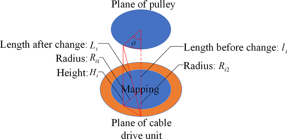
Pitch joint coupling diagram.
The change in rope length

The formula for calculating Li and li are as follows


where
Kinematic simulation
Verification of decoupling method
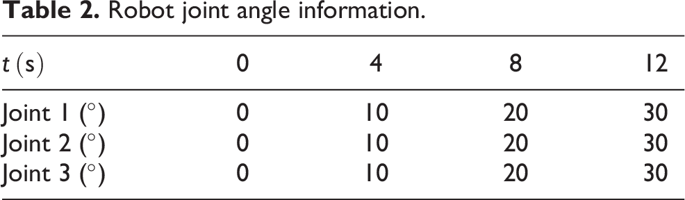
Aiming at the coupling phenomenon of joint motion, to verify effectiveness of the decoupling method, this article uses the established Mutibody model for forward kinematics simulation and takes the first three joints as an example to make the first joint, the second joint, and the third joint move separately. Equation (32) is used to conduct trajectory planning for the joint space with quintic polynomial interpolation, and the changes of joint angles are shown in the Table 2. Figure 13 shows the coupling effect of three joints moving alone on the other joints. When the first three joints are rotated individually, the maximum coupling angle is

Robot joint angle information.
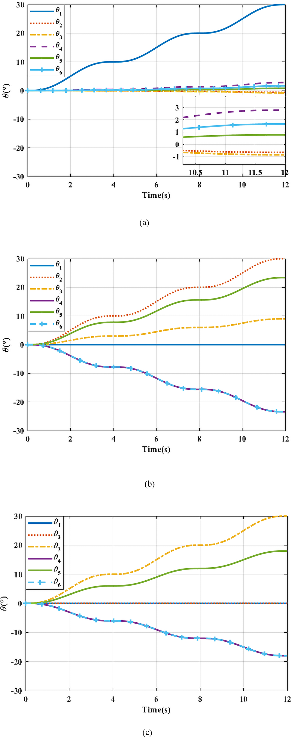
Coupling effects when the first three joints move alone: (a) joint 1 moves alone, (b) joint 2 moves alone, and (c) joint 3 moves alone.
The start angle of the joint at two adjacent points is
The decoupling method is added to the joint movement, and the first three joints are driven at the same time to obtain the motion of each joint, as shown in Figure 14(a), and the change in the length of the flexible cable is shown in Figure 14(b).

Decoupling verification: (a) change of joint angle after decoupling, and (b) change of cable length after decoupling.
It can be concluded that after adding the decoupling method, the movement of the six joints meets the expectation, and the coupling between the first three joints is nearly eliminated. However, there are still small errors in the last three joints, with a maximum error of
Kinematic verification
The Mutibody model is used to verify the kinematic simulation. Combined with the decoupling method and considering the coupling relation, the joint angle is converted into the angle of cable-driven unit, and the motion control of the humanoid CDHR is realized through the flexible cable transmitting motion. Firstly, the trajectory planning is carried out for the end-effector position. The trajectory equation is shown in the equations (31) and (32). The position control of the end-effector is realized by adding the inverse kinematics of the decoupling method. Secondly,
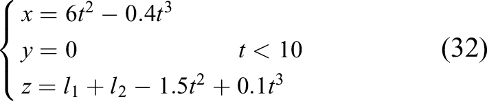

Figure 15 shows cable length variation, trajectory tracking and error, orientation change and error, respectively. Figure 15(b) and 15(c) verifies that the end-effector position changes meet expectations. According to Figure 15(c), the error of actual trajectory and the expected trajectory of the simulation is within 0.25 mm, and the maximum error of X-axis is 0.22 mm, Y-axis is 0.19 mm, and Z-axis is 0.01 mm. Figures 15(d) to (f) verify that the end-effector orientation changes meet expectations. It should be noted that, due to the use of proportional-integral-derivative (PID) control at this time, the tracking error of the robotic arm’s motion trajectory exhibits a gradual increase at the beginning, followed by repeated oscillations within a certain range during the motion process. The error of actual rpy and the expected rpy of the simulation is within 0.0015 rad. The reason for error is that the coordinate transformation of Mutibody modeling is incorrect and the coupling compensation of the rotary joint does not consider the change of the tangential point between the cable-driven unit and the pulley.

Kinematic verification: (a) diagram of cable length variation, (b) trajectory tracking diagram, (c) trajectory error diagram, (d) orientation comparison chart, (e) diagram of orientation change, and (f) orientation error diagram.
From the simulation results, it can be seen that the end-effector pose meets the expectations with small errors, which verifies the effectiveness and correctness of the decoupling method and kinematic algorithm.
Control method design
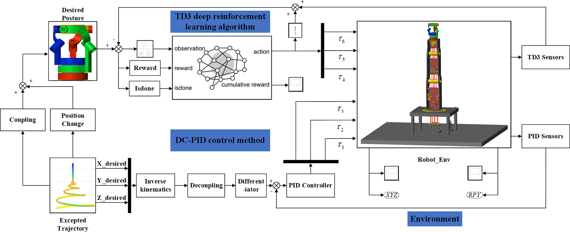
For the humanoid CDHR studied in this article, considering its complex nonlinearity, coupling characteristics, uncertainty of dynamics parameters, and the stress of the flexible cable should be considered, this article combines the hybrid characteristics of the robot with DC-PID control and TD3 DRL algorithm for dynamics control, so as to achieve trajectory tracking and orientation control.
The complete control flow of CHDR is shown in Figure 16. Based on the predefined desired trajectory, the desired position X_desired, Y_desired, and Z_desired of the serial part end effector of the robotic arm at the current time is obtained. Then, the desired joint angles are calculated through inverse kinematics and joint decoupling, and input into the PID controller to obtain the joint torques

Control system block diagram.
PID control based on decoupling method
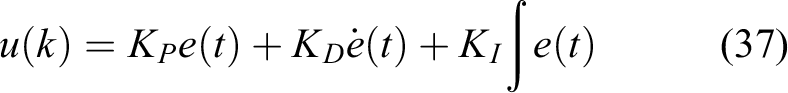
Combined with the characteristics of the humanoid CDHR studied in this article, the DC-PID control method is adopted to realize the position control of the end-effector. PID control algorithm is simple, robust, and reliable. Classical PID control algorithm can be discretely expressed as

Based on the angular dynamics model to realize the position control of the humanoid CDHR, it is first necessary to carry out the inverse kinematic solution to transform the Cartesian space into the Joint space to obtain the desired trajectories

where the output x
1 and x
2 of the differentiator are

So the following control law is obtained by combining the classical PID control
where
Using the above equation, the actual angles and angular velocities of the three series joints are observed as feedback variables, and the actual angles and angular velocities of the cable-driven unit are obtained from the radius relationship. The desired angles and angular velocities of the cable-driven unit are obtained by inverse kinematics, decoupling method, and third-order integral chain differentiator. The differences are substituted into the control law, and the errors are reduced by continuous iteration, so that the end-effector position finally meets the expectation.
The complete control system block diagram is shown in Figure 16. First, based on the desired trajectory, the desired position X_desired, Y_desired, and Z_desired of the robotic arm at the current time t is obtained. Then, the desired angles
TD3 deep reinforcement learning algorithm
The double delay deep deterministic policy gradient (TD3) 38 –40 reinforcement learning algorithm is an actor-critic based online heterogeneous DRL algorithm for solving the problem of continuous control of an intelligent agent outputting continuous actions. In DRL, for the problem that the algorithm falls into suboptimal strategy due to overestimation of Q value and the model is difficult to converge, TD3 algorithm combines DDPG and Double Q-learning, adopts two sets of networks to estimate Q value, selects relatively small as the updating target, and adopts conservative method to avoid over-high estimation of Q value. It also adds the skill of smoothing the target strategy. When calculating the target value, the noise disturbance is added to the action of the next state, which makes the value evaluation more accurate.
In addition, the TD3 algorithm adopts a delayed update strategy, that is, the critic network is updated many times and then the actor network is updated, which weakens the influence of overestimate deviation and enhances the stability.
Figure 17 describes the network structure of the TD3 algorithm, where s
t
, a
t
, and r
t
, respectively, represent the state, action, and reward at time t.

TD3 network structure.
TD3 has two critic networks for fitting Q function (value function), avoiding overestimation by selecting a small Q value to enhance stability. Each critic network contains two copies of neural networks, namely, online and target. Actor network is used to fit deterministic strategy gradient function, which also contains two neural network copies online and target.
In the update process of TD3 algorithm, it adopts two critic networks and chooses a small Q value when calculating the sequential difference target value yt
. In addition, for the purpose of smoothing the target strategy, small noise
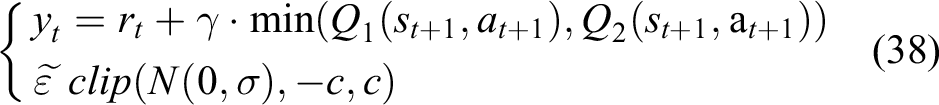
where
Gradient descent is performed on the critic network according to the loss function, and the neural network parameters of online evaluator network 1 and online evaluator network 2 are updated

Then
Finally, during the training, soft update is adopted to update the target actuator network and target evaluator network

where
State and action space design
In the process of humanoid CDHR movement, the pose of the end-effector relative to the base coordinate system will change due to joint coupling and end-effector position change. To achieve the dynamics control of end-effector orientation and obtain the desired orientation, the TD3 DRL algorithm is adopted to conduct orientation training for the coaxial SPM. The action space and state space are designed as follows:
The dimension of the action space is designed to be 3, and each action is defined as a torque signal (transmitted through the flexible cable) driving each joint of the coaxial SPM, and normalized (0–1).
The dimension of the design observation space is 15 and is defined as follows: The angles of the three joints Yaw, pitch, and roll angles at the end-effector and yaw, pitch, and roll angular velocities. Action value of the previous time step
Reward function and termination condition design
In this article, TD3 algorithm is used to train the end-effector to achieve the desired orientation. To make the model training reach convergence and stability faster, a reward function combining continuous reward and sparse reward is adopted to encourage the agent to learn the optimal strategy as soon as possible and achieve the desired orientation target. The reward function of the design agent is

where r
1 is the continuous reward for whether the motion of the first joint of the coaxial SPM exceeds the allowable motion range.


Similarly, the same is true for the second and third joints of the coaxial SPM.


To achieve the pose target, a sparse reward designed by whether the orientation at end-effector of the robot reaches the target range in each episode is used. Divided into three ranges of reward values, a Boolean judgment is used, with a Boolean value of 1 for meeting the condition and 0 otherwise

The same is true for the end pitch and yaw angles


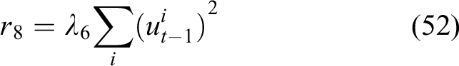
Consider the cost of performing the action, providing a constant reward at each time step and subtracting the penalty for the action performed at the previous time step

where Ts and Tf are environmental sampling time and environmental final simulation time, respectively.
To avoid the agent from over-exploring and wasting too much time in areas where the target is obviously not reached, a reasonable interval should be set for restriction. The yaw, pitch, and roll angles of the end-effector are judged by Boolean, and once the interval is exceeded, Isdone is set to 1 to end this episode and go to the next episode

Algorithm flow
In summary, the dynamics control process of the humanoid CDHR based on the DC-PID-TD3 algorithm is shown as follows:
DC-PID-TD3 algorithm update process.

Simulation verification
In this article, we use Simulink as the simulation environment, in which the DC-PID control and TD3 reinforcement learning training are carried out simultaneously. The control block diagram is shown in Figure 18, the desired trajectory equation is shown in equations (33) and (34), and the desired orientation is that the normal vector n of the moving platform is always perpendicular to the ground.
Control system block diagram.
Simulation parameter setting
The DC-PID-TD3 parameters are shown in Table 3. The proportional gain KP
controls the proportional relationship between the feedback signal and the error signal of the PID controller and is used to adjust the system’s response speed and stability. Increasing KP
can increase the system’s sensitivity and response speed, but it may also lead to oscillations and overcorrection. The integral gain KI
controls the integral part of the error signal in the PID controller and is used to eliminate static errors and biases in the system, thereby improving stability and accuracy. Increasing KI
can speed up the system’s stabilization process, but it may also lead to overshoot and oscillations. The derivative gain KD
controls the derivative part of the error signal in the PID controller and is used to predict the system’s future trend, thereby improving response speed and suppressing oscillations. Increasing KD
can reduce overshoot and oscillations in the system, but it may also lead to increased noise and sensitivity. B refers to the number of samples randomly drawn from the experience replay buffer each time the model is updated during iterations. A larger mini-batch size typically helps to obtain a more accurate estimation of gradients, thereby accelerating the convergence speed of training. On the other hand, a smaller mini-batch size sometimes leads to better generalization performance. E controls the number of training iterations the model undergoes over the entire data set. More epochs are beneficial for improving the model’s generalization ability. However, excessive epochs may lead to overfitting. Mcontrols how many times the model sees the data within each epoch. More steps per epoch help to accelerate the training speed and improve the model’s convergence. However, too many steps per epoch may lead to overfitting to the training data and make the model more susceptible to noise in the training data. The role of Tn
is to influence the perception of dynamic changes in the environment. A smaller sample time can provide more frequent feedback, allowing the algorithm to explore the environment more quickly and make real-time adjustments. On the other hand, a larger sample time can reduce computational burden, decrease hardware resource requirements, and improve the efficiency of data sampling. n refers to the number of hidden layers in the neural network. Having more hidden layers can give the neural network a stronger fitting ability, enabling it to learn more complex function relationships. However, having too many hidden layers might also lead to overfitting, increased training time, and computational resource requirements. s specifies the number of neurons in each hidden layer. A larger size of hidden layers can increase the fitting ability of the neural network, enabling it to better learn and adapt to complex data patterns. However, an excessively large size of hidden layers might lead to overfitting, especially when dealing with a small data set or in the presence of significant noise. D is a data structure used to store the experience data generated from the interaction between the agent and the environment. A larger replay buffer can store more experience data, helping to reduce the correlation between samples. However, a larger replay buffer will increase memory consumption and lead to longer training times.
Description of the parameters used by DC-PID-TD3.

To further validate the effectiveness of the DC-PID-TD3 controller, we also conducted simulations using a simple conventional PID controller, with the PID controller parameters shown in Table 4.
The parameters used by conventional PID.

Simulation result
As shown in Figure 19, Figure 19(a) and (b) depicts the trajectory tracking and error using the DC-PID control, and the maximum error of X-axis is 0.26 mm, Y-axis is 0.29 mm, and Z-axis is 0.02 mm. Figure 19(c) to (e) depicts the training results (average reward) using TD3 DRL, the trained orientation variation and the orientation change of end-effector, and the maximum error of roll is

DC-PID-TD3 simulation results graph: (a) trajectory tracking diagram, (b) trajectory error diagram, (c) training reward chart, (d) orientation change chart, (e) diagram of orientation change, (f) tandem joint drive torque diagram, (g) parallel joint drive torque diagram (normalized), and (h) diagram of orientation change (conventional PID).
Experimental evaluation and validation
Based on the previous kinematic analysis, coupling analysis, and control algorithm simulation, the experimental object is the humanoid CDHR, and the relevant experiments are verified based on TwinCAT3 and Matlab software platform.
Experimental setting
This experimental platform is mainly composed of the upper computer, electrical control system, robot body, and motion capture system. The upper computer is implemented by TwinCAT3 and Matlab software platform. Matlab is responsible for the implementation of the motion control algorithm, and TwinCAT3 is responsible for the control of the lower computer. Electrical control system includes controller, driver, IO module, servo motor, ball screw, and so on. The robot is the humanoid CDHR prototype. The motion capture system is to collect and detect the actual trajectory of the robot using Nokov camera, compare it with the theoretical trajectory, and verify the effectiveness of the decoupling method and control algorithm. Figure 20 shows the construction of the humanoid CDHR prototype.
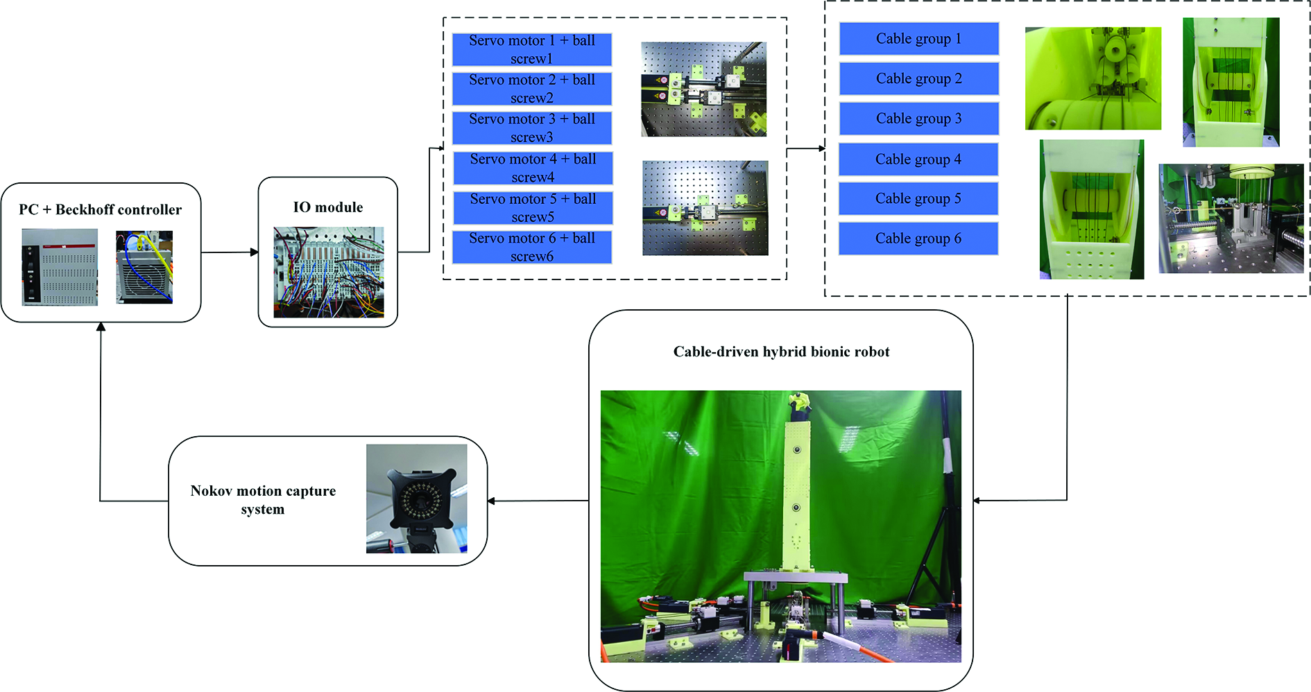
The humanoid CDHR prototype. CDHR: cable-driven hybrid robot.
Experimental analysis
Experimental validation of the decoupling method
To verify the feasibility and effectiveness of the decoupling method in practical application, the first three joints of the cable-driven hybrid robotic arm experimental prototype are trajectory planned, and each joint is rotated according to the motion law in Table 5, and the experiments are conducted in the coupled and decoupled states, respectively, and the turning angles of each joint are collected by the motion capture system and compared with the desired turning angles. Figure 21 shows the experimental verification diagram of the decoupling method.
Robot joint angle information.

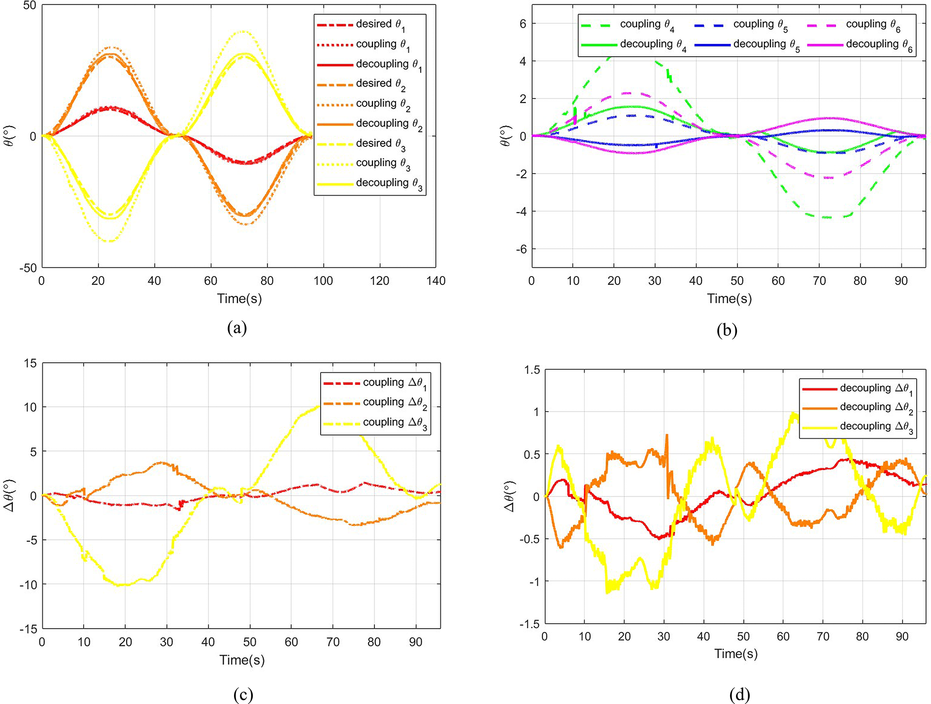
Experimental validation of the decoupling method: (a) angle 1,2,3 changes in two states, (b) angle 4,5,6 changes in two states, (c) error in the coupling state, and (d) error in the decoupling state.
From the above experimental results, we can see that in the coupled state, the maximum error of six joint rotation is about
Experimental verification of DC-PID control
In this paper, the PID control based on the decoupling method is experimentally verified, and the mutually independent position information of each joint is obtained on the basis of the inverse kinematic solution and decoupling method, then PID control is adopted to realize the trajectory tracking of the end, and the trajectory equation as Eq. 33 - 34. The SDK of Nokov motion capture system is used to provide real-time feedback of the series joint position information and the end-effector position information, and to compare the actual trajectory with the desired trajectory.
As shown in Figure 22, the maximum errors of open-loop trajectory tracking are 1.56 mm, 0.85 mm, 1.27 mm. The maximum errors of PID control trajectory tracking are 1.38 mm, 0.55 mm, 0.76 mm. Compared with open-loop experiment, The maximum error of trajectory tracking is reduced by 11.54%, 35.29% and 40.16%, respectively, which prove the good performance of the DC-PID control method.

Experimental verification of control method: (a) track tracking, (b) open-loop tracking error, and (c) DC-PID tracking error.
Multibody model of the humanoid CDHR is built based on the Simscape modeling environment, and the physical simulation is visualized to provide the environment basis for the later paper.
Secondly, the kinematic analysis of the robot is carried out, and for the joint coupling phenomenon caused by multijoint cable-driven, the decoupling method is proposed through joint coupling analysis, so that the motion of each joint does not affect each other, and accurate motion results are obtained, and the kinematic model is established.
Thirdly, to address the problems of complex nonlinearity, coupling, uncertainty of dynamics parameters, and considering the cable forces on the humanoid CDHR system, this article combines the hybrid characteristics of the robot and proposes a control method combining the DC-PID control and TD3 DRL algorithm to realize the trajectory tracking control and orientation training.
Finally, the prototype of the humanoid CDHR is built, and the verification experiments of the decoupling method and the control method are carried out, respectively, and the feasibility and effectiveness of the decoupling method and the control method are proved by the analysis of the experimental results.
In the future, further research will be conducted to improve the dynamics model of the humanoid CDHR and to establish a model-based intelligent control method from flexibility to meet the actual human–machine collaboration requirements.
Footnotes
Declaration of conflicting interests
The author(s) declared no potential conflicts of interest with respect to the research, authorship, and/or publication of this article.
Funding
The author(s) disclosed receipt of the following financial support for the research, authorship, and/or publication of this article: This study was supported by the National Key Research and Development Program of China (No. 2022YFB4702501), the National Natural Science Foundation of China (No. 52175013), and Key Science and Technology Special Project of Anhui Province (202203a05020007).