
Abstract
Path following presents a pivotal challenge within the realm of small fixed-wing unmanned aerial vehicles. Firstly, a Lyapunov-stable path guidance law was formulated to follow specific planar curved paths. To ensure differentiability of the guidance law, a modified, smooth saturation function was derived. Secondly, an analysis was conducted to ascertain the interrelationship between control parameters and input constraints, thereby identifying the relevant parameter domains. Thirdly, the nonlinear model predictive control technique was harnessed to optimize both guidance law parameters, enhancing the unmanned aerial vehicle’s capacity to achieve optimal performance in both straight-line and circular path following, hereafter referred to as PFC_NMPC. By leveraging Lyapunov stability arguments for switched systems, the stability of the corresponding nonlinear switched system was guaranteed. In this study, square and circular paths were generated to assess the path-following control of a simulated fixed-wing unmanned aerial vehicle. The performance of various guidance laws, including those with fixed parameters (PFC), those with parameters tuned using fuzzy logic (PFC_FL), PFC_NMPC, vector field, and pure pursuit with line-of-sight, was compared. Notably, the proposed PFC_NMPC method exhibited the ability to expedite the unmanned aerial vehicle’s convergence to the desired path while maximizing the effective flight path length.
Introduction
Small fixed-wing unmanned aerial vehicles (UAVs) have garnered substantial attention from researchers and users in recent times. These aircraft are extensively studied and employed to validate advanced control methodologies and address real-world challenges. 1,2 Notably, within the realm of UAV control technology development, the availability of stable path following control methods assumes a pivotal role. These methods constitute a fundamental component in realizing autonomous UAV flight capabilities.
Given the inherent nonlinearities in the dynamics and kinematics of fixed-wing UAVs, the application of nonlinear control technology is a logical choice to achieve stable path following control of these vehicles. Notably, among the various nonlinear control methods, those grounded in Lyapunov stability control theory are prominently featured in a substantial body of literature addressing UAV path following control.
Building upon the pure pursuit-based path following approach, a nonlinear path-following guidance technique, referred to as the L 1 guidance algorithm, has been developed, notable for its stability that remains unaffected by variations in velocity. 3 This L 1 guidance algorithm is capable of generating acceleration commands for the UAV in both horizontal and vertical planes, as well as corresponding bank angle commands through command transformation, thus enabling the tracking of 3D curved paths. 4 To facilitate path following control, especially in scenarios involving wind disturbances, including those with unknown wind disturbance information, an L 1 adaptive control method has been devised. This method exhibits robustness against time-varying wind conditions, achieved through the utilization of a linearized model dynamics. 5
Another approach employed for path following is the vector field method, which furnishes the desired course angles for each point along the specified path. Typically, the sliding mode technique is utilized to achieve zero cross-track error. In their work, the authors have introduced a standard vector field approach for both straight and circular path following controllers. 6 To address challenges posed by unknown wind conditions or unmodeled course angle dynamics, an adaptive vector field-based guidance law has been formulated. 7 Furthermore, in consideration of minimum turning radius constraints for the UAV, a Gaussian filter has been employed to smooth the discrete vector fields generated by the proposed algorithm. 8 Zhao et al. harnessed the input-to-state stable properties to design control laws, with the error kinematic model being grounded in the vector field approach. 9 For achieving precise 3D Dubins-style instructive path following, even in the presence of disturbances, the authors have introduced an enhanced vector field path following method. 10
Drawing from the concept of tracking a virtual target along a predefined straight-line path, a straightforward guidance law was devised, taking into account the aircraft’s maneuvering capabilities. 11 The integral light-of-sight guidance logic was implemented to compute the vehicle’s course angle, with the optimization of lookahead distances achieved through the application of the nonlinear model predictive control (NMPC) technique. 12 In scenarios where the guidance law must account for the dynamics of the heading rate or bank angle, the backstepping technique proves valuable. This technique permits the systematic development of the desired control law within the framework of the Lyapunov theory, guiding the design process in a step-by-step manner. 13,14
In certain studies, the incorporation of input constraints has been a key consideration when designing guidance laws. Among the nonlinear design methodologies, the nested saturation technique emerges as a viable approach for addressing such issues. For instance, in the development of a 3D path following controller, the nested saturation technique was employed to account for constraints on roll and flight path angles. 15 To address the challenge of 2D curved path following for fixed-wing UAVs under conditions involving both wind and control constraints, the nested saturation theory was effectively applied. 16
The efficacy of the aforementioned guidance methods, founded on Lyapunov stability theory, has been corroborated through simulations or experiments. It is important to note that in these controllers, the majority of control parameters remain constant to uphold the stability of the associated closed-loop nonlinear systems. However, when the aircraft confronts external wind disturbances during route transitions or in-flight, the fixed controller may not assure consistent optimal performance in path following control. Therefore, it is prudent to contemplate the real-time adjustment of controller parameters while maintaining system stability to attain optimal path following control performance.
In prior studies, 17,18 a PD-like control law for straight path following, rooted in the kinematic model, was devised. Notably, the derivative-like (D-like) parameter was fine-tuned using manually crafted fuzzy rules to enhance path following performance. Nevertheless, it is essential to recognize that artificially designed rules may not encompass all potential scenarios encountered by the vehicle during its flight. Furthermore, the proportional-like (P-like) parameter remained fixed, which presents inherent limitations in addressing diverse and dynamic conditions.
The NMPC technique, renowned for its predictive capabilities and constraint handling, has found application in addressing nonlinear guidance challenges for fixed-wing UAVs. 19,20 These applications encompass both complete dynamic models and simplified kinematic models. While some researchers have formulated guidance laws using the open-loop NMPC approach, the stability of the resulting closed-loop systems remains uncertain. 21,22 In contrast, when employing NMPC with closed-loop system stability, it becomes imperative to establish certain sufficient conditions. 23,24 It is worth noting that the closed-loop stable NMPC method demands significantly greater computational resources compared to the open-loop NMPC approach.
Building upon the insights gleaned from the preceding discussions, this study introduces a PD-like smooth planar path following control law, which is an extension of the straight path following control law. 17 In this approach, the NMPC technique is harnessed to optimize both the P- and D-like parameters. This optimization process is aimed at ensuring that the vehicle consistently delivers optimal path following performance throughout its flight. Furthermore, to guarantee the stability of the associated closed-loop nonlinear systems, the study leverages Lyapunov stability arguments within the context of switched systems. This contributes to the overall robustness and reliability of the proposed control methodology.
This study presents significant contributions: Firstly, it leverages Barbalat’s lemma to formulate a guidance law for following smooth planar paths, involving the derivation of a modified smooth saturation function. Input constraints are thoughtfully accounted for, and the domains of control parameters are determined through a comprehensive analysis of their relationship with these constraints. Secondly, the study pioneers the application of open-loop NMPC technology to optimize all control parameters within the guidance laws. The stability of the corresponding nonlinear switched system is rigorously ensured through the adept use of Lyapunov stability arguments concerning switched systems. The effectiveness of the proposed method was verified via a six-degrees of freedom (6-DOFs) simulation of a fixed-wing UAV. Thirdly, the efficacy and exceptional path following performance of the proposed PFC_NMPC method are rigorously examined through simulations using the Aerosonde UAV model. These results are meticulously compared with other methods, including fixed parameters (PFC), parameters tuned using fuzzy logic (PFC_FL), vector field (VF), 6 and pure pursuit with line-of-sight (PLOS). 25 These contributions collectively enhance our understanding and application of path following control methodologies for unmanned aerial vehicles.
To the best of our knowledge, this proposed method represents a pioneering approach. The remainder of this paper is structured as follows. The second section presents the problem formulation. In the third section, we derive the guidance law for planar smooth path following, featuring fixed control parameters. The fourth section outlines the comprehensive process of optimizing control parameters for both straight and circular path following guidance laws using the open-loop NMPC technique. It also delves into the relationship between control parameters and constrained commands. In addition, we provide a stability analysis of the corresponding switched nonlinear system. The fifth section offers simulation results and discussions pertaining to square and circular path following. Finally, in the sixth section, we draw conclusions and present remarks on the study.
Problem description
Assuming that the fixed-wing UAV is equipped with an autopilot capable of precisely adjusting to the desired altitude and airspeed, the aircraft can effectively maintain horizontal flight. When operating within a horizontal plane, the kinematic model of the aircraft can be described as follows 26

where (x, y) is the center of mass of the vehicle in the inertial horizontal coordinate system, Va
, Vg
,

The schematic diagram of UAV following the desired horizontal path. UAV: unmanned aerial vehicle.
To design the guidance law, the course rate control

When the UAV is flying, the assumptions that are appropriate for the actual situation include:
Assumption 1
The groundspeed Vg
and its derivative
Assumption 2
The control
This article considers the planar smooth paths that can be expressed by quadratic differentiable functions as

The value of
To acquire the azimuth information of the UAV relative to the target position, it is essential to compute the first-order partial derivative and gradient magnitude of the function

For the target path, if there are places in the horizontal plane where the gradient modulus of
Assumption 3
The first- and second-order partial derivatives of the function
Path following guidance law with fixed control parameters
The purpose of the guidance law is to enable the UAV to follow the target path in the correct direction. As show in Figure 1, the desired orientation

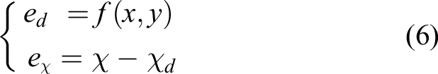
Introducing the virtual distance error ed
and course angle error
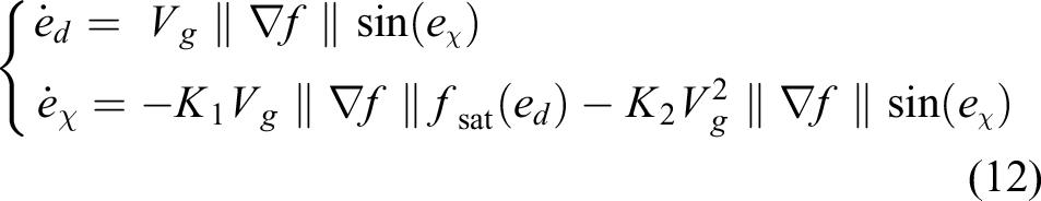
The time derivatives of ed
and

Theorem 1
For the error model shown as equation (7), the control law

can asymptotically drives ed
and
In equation (8), the two control parameters K
1 and K
2 are positive constants. The saturation function

where x 0 is an arbitrary given positive constant.
The function
It should be noted that the saturation function

Define the relative difference between
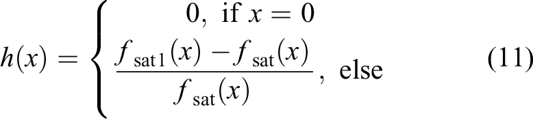
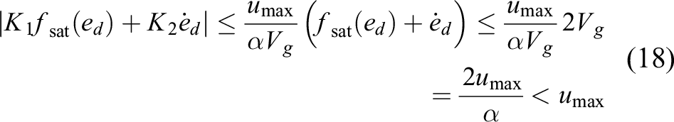
It can be found that the maximum absolute value of

The comparison of the two functions
Thus, the function
Proof
Substitute
Define the state vector

where

Under Assumptions 1 and 3,

It has the fact that
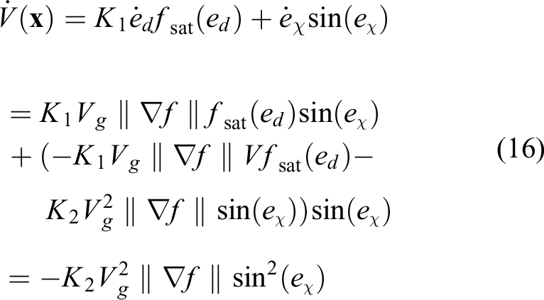
Thus,
Path following controller with parameters optimized by NMPC (PFC_NMPC)
Under any given initial condition, the magnitude of the two parameters K
1 and K
2 have a significant impact on the response characteristics of the system (12).
27
Due to the fact that any smooth path on a plane can be approximated by a combination of several straight or circular segments, this article only considers the path following control of straight and circular paths and the optimal design of their parameters. When appropriate expressions are used for the desired straight line and circular paths, the gradient modulus of these functional expressions are equal to 1,
26
which is very convenient for subsequent optimization calculations. The functional expressions for the desired lines and circles are
Straight-line path following controller with parameters optimized by NMPC
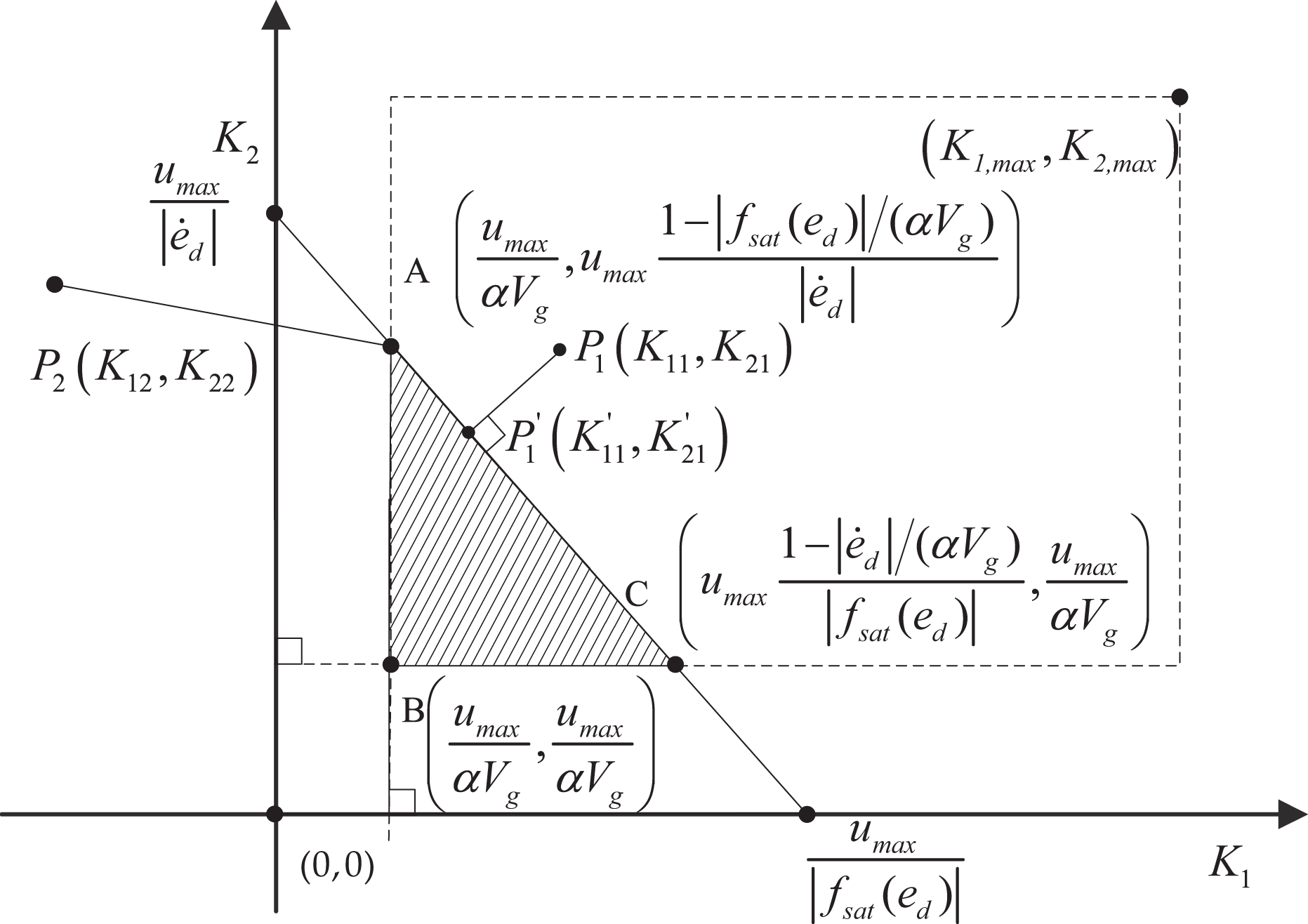
The relationship between Ki
and
with constraint
During the optimization process, the control parameters

Because
The proposed path following control method with control parameters optimized by NMPC was presented as Figure 3. The inner-loop control module stabilizes the dynamics and tracks the reference control signals. The pitch angle command achieves the altitude hold. The path generator module generates the desired flight paths.

The structure of the proposed controller.
In this study, we set
The parameters set

The parameters set
During optimization calculation, if the currently obtained parameter solution

For the points P
1 and P
2 shown in Figures 4 and 5, the solutions to (19) are
The parameters optimization algorithm for straight-line path following
Assume a sampling interval of duration

where
In the case of straight-line path, the terms

where SD
,
To optimize the control parameters

Then,

The relative equality constraint (20) becomes as

Then, the optimized parameters

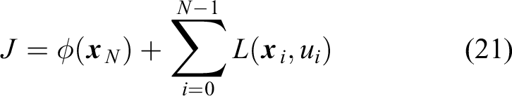
Similar to the indirect method of Lagrange Multipliers for solving the optimization problems using open-loop NMPC technology, 31 the cost function J can be rewritten as

where
Here, we can get the Hamiltonian term

In addition, the derivative of J can be derived as

The Lagrange multiplier


Then,

Thus, if x
0 is constant, an N predictive control parameters
do
compute
compute
compute
compute
update
and limit
reduce the step size h by
update
The parameters related to the above iterative process, including
The stability analysis of systems with time-varying parameters
Lemma 1. 30
Suppose we have a finite number of Lyapunov functions Vi
,
In this article, the parameters of each sampling interval remain unchanged, so during a complete flight time, we obtain the following time-varying nonlinear model as
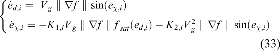
Here, i represents the model within the time range of
Circular path following controller with parameters optimized by NMPC
To facilitate the optimal calculation of the control parameters of the circular path following controller, the polar coordinates are applied to describe the kinematics of the vehicle. In Figure 6, the polar coordinates are established with the canter of the circle as the origin. The position and the velocities of the vehicle can be described as


The polar coordinates for the UAV. UAV: unmanned aerial vehicle.
Where
Taking the derivative of the two sides of (34) with respect to time, and considering the dynamics (35), it can be derived that
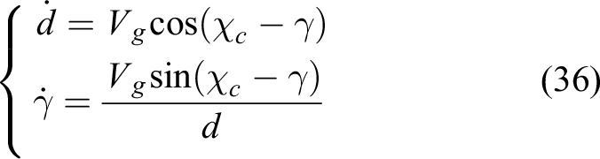
Thus, the model used for the design of a circular path following controller can be represented as

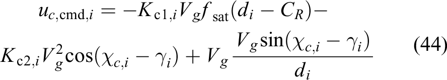
Furthermore, the guidance law (8) for circular path following can be expressed as

where the parameters
The relationship between
and
with constraint
For any given state

The set

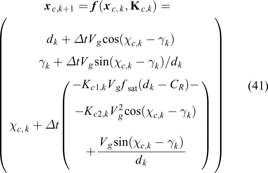
The parameters optimization algorithm for circular path following
While using the NMPC technique to optimize the control parameters for circular path following, the discrete-time equality constraints can be derived from (37) as
The cost function with equality constraints can be defined as

For the circular path following, we have
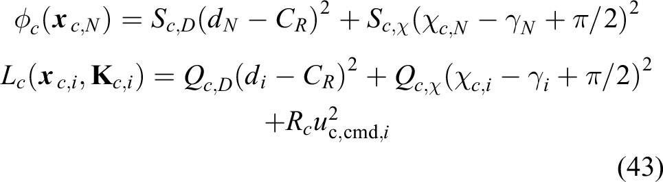
where
Then, the optimized parameters can be obtained by solving the optimization problem shown as

The processing for calculating the parameters
Simulation
The simulation research was carried out in the environment of Matlab/Simulink. An Aerosonde UAV model containing standard 6-DOF nonlinear dynamics is used for simulation purposes.
23
The wingspan of the UAV is 2.9 m. Figure 7 shows the overall framework of the simulation, which includes the Aerosonde UAV model, the stable inner-loop controller, and the proposed path following controller. During the simulation, the UAV adopts the bank-to-turn manoeuvre without sideslip. The commanded bank angle was tracked by a well-tunned inner-loop PD controller. With the command

where g is the acceleration of gravity.

The simulation in the Matlab/Simulink environment.
The parameters involved in the optimization processing, the wind, and the controller are listed in Table 1. The methods of using the fuzzy logic to adjust the parameter K 2 in the control law (8) (PFC_FL), 28,30 VF, 6 and PLOS 25 were also applied for comparison.
The parameters for simulation.

Square path following
The desired planar square path is depicted in Figure 8(a). In addition, Figure 8(b) presents a comparative analysis of path following results employing five distinct methods: PFC, PFC_FL, PFC_NMPC, VF, and PLOS. During the UAV’s navigation along the square path, the aircraft initiates route switching approximately 200 m in advance to effectively manage transitions.

The square path following result using the five methods. (a) the position, (b)
Performance indexes of square path following using the five methods.

The response performance to linear paths can be reflected by the following three indexes: (1) the effective length of the predefined line path followed (LOPLPF), (2) the convergence time, and (3) the error overshoot. First, the effective flight time of the vehicle on a given straight line path is defined as the time from
According to the definition of the straight-line equation,
The three performance indexes LOPLPF, convergence time, and error overshoot are listed in Table 2. Compared to the other two methods, the LOPLPF of each segment for the aircraft to follow the square path based on the method PFC_NMPC is the longest. During the flight of the first six segments, the total LOPLPF obtained by PFC, PFC_FL, PFC_NMPC, VF, and PLOS are 11234.37 m, 10767.91 m, 12289.03 m, 10979.33 m, and 12170.22 m, respectively. This indicates that the vehicle can obtain the longest effective flight path using the method PFC_NMPC. The convergence time listed in Table 2 also shows that the method PFC_NMPC makes the UAV converge the predefined path with the shortest time.
Figure 8(c) to (f) presents the comparison of the parameters K
1, K
2, the course rate command
Circular path following
When designing the circular path following control simulation scenario, we designed the corresponding circular paths based on two concentric circles and set the aircraft to switch between the two circular paths at a certain position. The expressions for the two concentric circles are defined as

The circular path following result using the five methods: (a) the position, (b)
In a manner similar to the definition of LOPLPF for straight-line path following, we introduce the concept of the effective length of UAV following a predefined circular path (LOPCPF). LOPCPF is defined as the length of the actual flight path after the flight distance error
Performance indexes of circular path following using the five methods.

The above findings highlight that, through the optimization of parameters K 1 and K 2 using NMPC, the PFC_NMPC method harnesses the predictive capabilities of the NMPC technique. Consequently, this approach continues to empower the UAV to achieve more efficient flight paths, thereby inheriting the advantages of NMPC’s predictive capabilities.
Conclusions and future works
This article puts forth an innovative path following control approach for fixed-wing unmanned aerial vehicles. The core novelty lies in harnessing NMPC to optimize adjustable parameters within a Lyapunov-stable guidance law. This addresses inherent limitations of fixed control schemes and enhances adaptability to varying flight conditions. Specifically, the contributions are threefold: (1) A smooth planar path following control law is formulated, grounded in Lyapunov stability arguments. This accounts for input constraints through a tailored saturation function. (2) Open-loop NMPC is uniquely employed to optimize proportional and derivative-like gains by transcribing the underlying continuous optimal control problem. This tuning empowers consistent tracking along straight and circular paths. (3) Stability of the resulting nonlinear switched system with time-varying parameters is ensured based on Lyapunov analysis for switched systems. Simulations showcase the proposed technique’s exceptional performance over alternatives, facilitating rapid path convergence and maximized trajectory consistency. The approach and results advance the state-of-the-art in real-time nonlinear path following control for unmanned aerial systems.
In summary, this study pioneers the optimization of adaptive guidance laws via NMPC for fixed-wing UAVs through a stability-assured, performance-centric integration. The domain-specific advancements hold promise in enhancing autonomous flight capabilities.
In future control design efforts, the dynamic response model of the roll angle during bank-to-turn maneuvers will be taken into account. The commanded bank angle will be derived from the course rate command using the backstepping technique. Furthermore, to address the presence of unmodeled components or other disturbances, consideration will be given to the application of fuzzy and neural approximation techniques. 33,34 These techniques have the potential to enhance the path following performance of unmanned aerial vehicles in real-world environments, making them more robust and adaptable.
Footnotes
Declaration of conflicting interests
The author(s) declared no potential conflicts of interest with respect to the research, authorship, and/or publication of this article.
Funding
The author(s) disclosed receipt of the following financial support for the research, authorship, and/or publication of this article: This study was partially supported by the National Natural Science Foundation of China (Grant No. 61503172), the Natural Science Foundation of Fujian Province (Grant No. 2020J05197), and the Xinluo District Industry University Research Technology Joint Innovation Project (Grant No. 2022XLXYZ002).