
Abstract
The manipulate load system of a helicopter driving simulator is a complex mechatronic system. To simulate the load system of the joystick more effectively, this study provides a new manipulate mechanism with automatic position reset function that integrates a spring system within the joystick. The load simulation of this manipulate mechanism can be achieved by designing the nonlinear coefficient of the spring in a reasonable manner, thereby eliminating the need for complex control of motor simulation and system time delay. This greatly simplifies the complexity of the system and effectively meets the requirements of real-time and accuracy. Initially, the new manipulate mechanism is described in detail through kinematic analysis. Then, dynamic simulation is conducted in ADAMS software to simulate the motion of the operation mechanism. Considering the active–passive relationships between the manipulate mechanism and the driving simulator, a mapping is established to achieve synchronized motion. The synchronized motion is subsequently evaluated and verified in MATLAB/Simulink. The results reveal that this new manipulate mechanism has high reliability and can effectively achieve synchronized motion with the driving simulator. The new manipulate mechanism will be useful in advancing research into the design of manipulate mechanism processes.
Introduction
The helicopter driving simulator is an important simulation equipment in the process of pilots’ daily training and aircraft development. It has the feature with strong flexibility, safety, low cost, and high fidelity. 1 The level of helicopter driving simulator from low to high contains level A, level B, level C, and level D, respectively, of which level D simulator is the highest level of flight simulator at present. The high-level helicopter driving simulator has more professional technical specification requirements and is the best assistant for helicopter pilots’ flight training, but the price is also extremely expensive, even higher than the real helicopter, and the cost usually reaches millions or even tens of millions of dollars. Low-level simulators are mainly suitable for flight enthusiasts to experience helicopter flight, learn flight knowledge, and improve flight experience. As a virtual development platform, simulator can not only accelerate the development cycle and design iteration speed but also make real-time teaching, dangerous scene testing, massive testing, and other things that are difficult to achieve in traditional ways become simple, even the construction of surreal scenes.
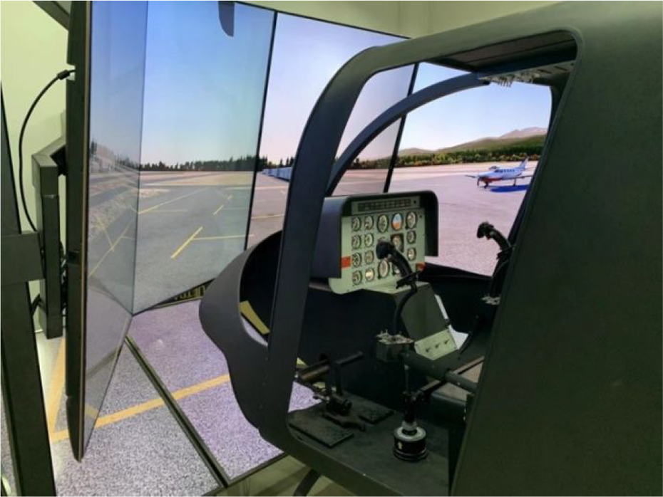
Most driving simulators are developed based on Stewart’s six-degrees of freedom (DOFs) platform. At present, scholars from different countries have made a lot of research in the field of design of driving simulator and control platform. A space adaptive sliding-mode controller is proposed based on the dynamic equation of the six-DOFs flight simulator platform. The controller has good robustness. 2 A six-DOFs flight simulator based on electric drive improves the stability and frequency response performance of the platform through particle swarm optimization algorithm. 3 Inverse dynamics control is applied for the motion system of a six-DOFs flight simulator. 4 Two methods to make the six-DOFs platform run smoothly are introduced. 5 The results show that the tracking acceleration can significantly improve the motion accuracy of the six-DOFs platform compared with the tracking displacement. An adaptive neuro fuzzy controller is designed to control the Stewart platform of a six-DOFs parallel robot. 6 The physical drawing of the helicopter driving simulator is developed by Nanjing Quankong Aviation Technology Company as shown in Figure 1.

Prototype of helicopter driving simulator.
The manipulate load system is an important part of the helicopter driving simulator. It mainly provides the pilot with a real-time and accurate sense of control force, helps the pilot judge the flight status, and then sends out real-time control information to the simulator. As a key component in the control load system, the control mechanism is mainly used to control the roll and pitch of the whole simulator. 7,8 Therefore, the performance of the control mechanism has a very important impact on the stable operation of the whole simulator and the pilot’s sense of experience. Many scholars have studied the control load system. The force sensing simulation of the control load system, the device of the control system, and the electrically driven control load system have studied. 9 –12
At present, the simulation of joystick load is mainly realized by means of motor plus control. The whole system is complex. So, this paper tries to find a new scheme. For the manipulate mechanism of driving simulator, there is little research and development. A manipulate mechanism is applied in driving simulator as shown in Figure 2. A parallel six-DOFs force feedback handle controlled by electrohydraulic servo is designed. 13 The handle can transmit position, attitude, speed, force, and other information to the control target and has good performance. A bottomless joystick is designed, 14 which can represent the functions of the traditional joystick in midair. A new two-DOF force feedback sidebar is designed, 15 which has been developed and integrated into the studied flight simulator. A force reflecting sidestick controller is developed and integrated for flight simulator research. 16

A solution of manipulate mechanism.
At present, the synchronous simulation technology is relatively mature and has been applied to various fields. The motion synchronization and online simulation technology based on the parallel motion platform has studied. 17 –19 The method of generating optimal time synchronization trajectory of robot arm is introduced. 20
For the helicopter driving simulator, the special carrier equipment research center of Yanshan University has already made some research achievements. It is shown that the prototype picture of the helicopter driving simulator in Yanshan University in Figure 3. A sliding motion mechanism is proposed by improving the anti-collision simulation model of shipborne helicopter landing. Its reliability is analyzed, and the rationality is verified. 21 A dynamic model of tactile interface is proposed, and a simple control mechanism’s tactile interface and control strategy for helicopter driving simulator are designed. The data are processed through genetic algorithm, and finally the rationality and effectiveness of the design are verified in experiments and reported. 22 A new manipulate joystick structure for helicopter driving simulator is designed. 23 The structure has compact layout, high accuracy performance, automatic reset function, and direct force feedback.
Helicopter driving simulator in Yanshan University (Bell 206).
In this paper, the helicopter driving simulator is located on a Stewart platform as the control object, a new manipulate mechanism with a designable load system by spring is developed. The performance of the manipulate mechanism has been further optimized based on the former paper. 23 The manipulate mechanism can realize the load simulation of the joystick by spring compression. This load is generated by mechanical structure, and the load force regulation feature can be achieved by designing the nonlinear elastic coefficient (i.e. stiffness coefficient) of the spring, which replaces the complex control system of motor simulation and time delay. It is a low cost and easy to operate solution. Then, the output of the manipulate mechanism is used to control the real-time attitude adjustment of the driving simulator to achieve the effect of synchronous simulation, and the rationality of the design is verified by MATLAB simulation.
Development of new manipulate mechanism
Introduction to the manipulate mechanism
The structural design and performance of the manipulate mechanism have a great impact on the simulation accuracy and the driver’s sense of experience. The driver can adjust the simulator attitude mainly by applying external force on the manipulate mechanism. The motion angle has a certain range limit and can automatically return to the initial state after the external force disappears. At the same time, the operator should feel the load force from the manipulate joystick as actual as driving a real helicopter. It has the function of automatic reset. In addition, the shape design of the handle and the mechanism motion working space should also be considered, which should be suitable for the grasp of hands, so as to bring comfort to the driver and indirectly improve the driver’s control accuracy. The previous generation of manipulate mechanism of Yanshan University is shown in Figure 4. On this basis, the new manipulate mechanism is developed in this paper by optimizing the rotating structure inside the cavity. Compared with the previous generation of manipulate mechanism, the new manipulate mechanism developed in this paper also has the following advantages while maintaining its original functions: Using the thrust joint bearing to replace nonmetallic ball joints, providing greater bearing capacity for handle operation, On the other hand, the thrust joint bearing can effectively control the bearing clearance with a high degree of standardization and make the handle feel more realistic and unified. The optimized design scheme improves the reliability of the handle and reduce the possibility of failure, at the same time it reduces the cost of parts largely. The spring system of the manipulate mechanism is optimally designed. The operation load can be obtained by altering the spring parameter to approach the real driving operation.

Previous generation manipulate mechanism of Yanshan University.
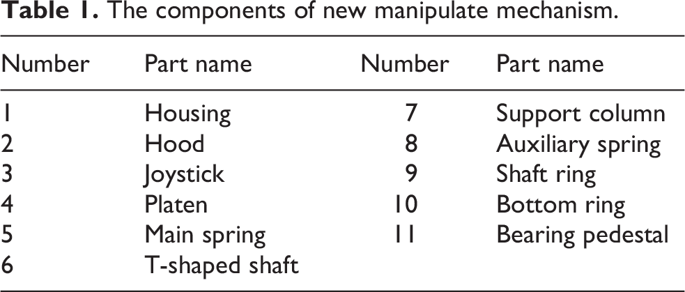
The sectional view of the new control mechanism developed in this paper is shown in Figure 5, and components are listed in Table 1.

New manipulate mechanism: (a) three-dimensional model and (b) half-cutaway view.
The components of new manipulate mechanism.
Here is the basic composition and working principle of the new control mechanism.
The new manipulate mechanism is mainly composed of thrust joint bearing (9, 10), main spring (5) with a certain amount of compression, four auxiliary springs (8), housing (1), hood (2), platen (4), joystick (3), and other main components. In the initial state, the springs are all in the compressed state. The initial elastic force of the main spring is used to keep the joystick in the vertical state all the time to prevent the joystick from tilting and loosening due to its own gravity. The auxiliary spring is used to prevent the internal cover from directly colliding with the lower base, mainly playing a buffer role. When a driving force is applied to the joystick, it will drive the shaft ring and bottom ring of the thrust joint bearing to move relatively. At this time, the platen is inclined, driving the cover to move upward, and the main spring is further compressed. When the driving force is gradually reduced to insufficient to overcome the elastic force of the main spring, the joystick will slowly return to the initial position. It can be seen that the new manipulate mechanism still has the function of automatic reset of the previous generation. It should be noted that the swing angle of the joystick is related to the size of the thrust joint. During a specific application, the specific size of the thrust joint can be designed according to the rotation angle which is required by the actual situation.
Kinematic modeling of manipulate mechanism
To facilitate the study of the kinematics and force relationship of the manipulate mechanism, the manipulate mechanism is extracted into design schematic as Figure 6. The three-dimensional sketch is shown in Figure 6(a), and the mechanism sketch of the manipulate mechanism is shown in Figure 6(b).
In Figure 6(b):
F1 is the applied driving force.
F2 is the contact force between the pressing plate and the upper surface of the inner cover.
F3 is the elastic force of main spring.
F4 is the elastic force of the auxiliary spring.
K1 is the stiffness of main spring.
K2 is the stiffness of the auxiliary spring.

Simplified model of manipulate mechanism: (a) three-dimensional sketch and (b) schematic diagram.
It can be obtained from torque balance

and formulated as

By the geometric relationship

it can be deduced
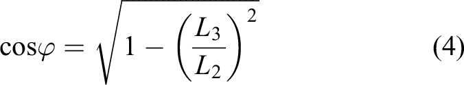
and
Put equation (4) into equation (2)
Focusing the cover as the analysis object, the vertical force can be obtained

where P 1 is the preload of the main spring and P 2 is the preload of the auxiliary spring.
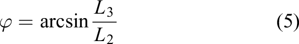
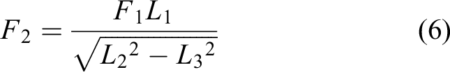
It can be formulated to obtain L 3
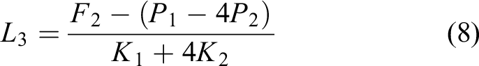
Put equation (8) into equation (5)
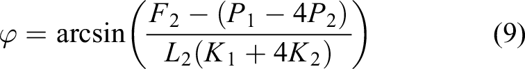
Put equation (2) into equation (9) to get the implicit relationship between deflection angle

The initial spring stiffness is given K
1 = 3.6 N/mm,
The functional relationship between the deflection angle

The curve of the given driving force is shown in Figure 7(b). In 1–6s, the first-order functional relationship between internal force and time is F
1 = 6t − 6, to get the functional relationship between

Figure 7 shows the function relation which is plotted by MATLAB.

Diagram of functional relation: (a) diagram of ϕ versus t and (b) diagram of ϕ versus F 1.
It can be seen from Figure 7(a) that the value of
Separate motion simulation of manipulate mechanism
In addition to adjusting the attitude of the helicopter, the manipulate mechanism of the helicopter pilot simulator should also have a load system to further improve the driver’s realistic sense of operation.
The purpose of dynamic simulation in this paper is to find the appropriate spring stiffness according to the expected load force in the joystick. In this analysis, the selection of the size parameters of the whole mechanism also plays a decisive role. On the premise of ensuring that the operating mechanism can realize its function properly, the contact force of each component of the operating mechanism should be kept as stable as possible during the steering process. If the force is accompanied by irregular vibration during the movement, the damage to the parts can be relatively large.
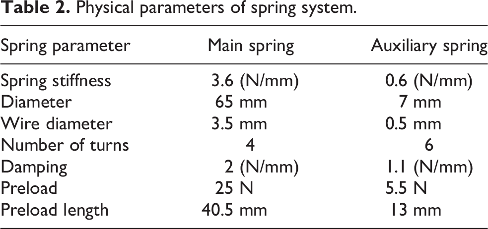
To better evaluate the stress of several key parts of the manipulate mechanism during rotation, it is necessary to carry out dynamic simulation of the manipulate mechanism separately. Dynamic simulation of the manipulate mechanism is carried out by ADAMS software in this paper. In the process of dynamic simulation, many experiments are carried out, and more reasonable size parameters and spring stiffness are obtained according to the comprehensive consideration of the stresses and spring stiffness of several. Some specific physical parameters of the springs are shown in Table 2.
A 3D model of the manipulate mechanism is created in INVENTOR, and imported into ADAMS, setting material properties, adding kinematic pairs and constraints, and applying force at the end of the joystick for driving. The simulated function of the force in ADAMS is defined as:
IF (time −1: 0, 0, IF(time −6: 6*(time −1), 30, IF(time −10: 30, 30, IF(time −15: −6*(time−10) +30, 0, 0))))
Physical parameters of spring system.
The function image is shown in Figure 8.

The curve of driving force.
The simulation model of the manipulate mechanism is imported into ADAMS, and the attitude when the joystick reaches the maximum rotation angle under the action of the driving force is shown in Figure 8.

Simulation model in ADAMS: (a) initial position and (b) position diagram of maximum motion.
The simulation process begins from initial position as Figure 9(a), to the maximum motion position as Figure 9(b). In the process of joystick motion, it is necessary to analyze the contact forces of several key parts.
The contact force curve between the platen and the inner upper surface of the hood is shown in Figure 10. From the force curve, it can be seen that at the beginning, the manipulate mechanism is in a static state. Under the action of main spring force, the initial contact force is 2.78 N, which is to ensure that the joystick is always in a vertical state and prevent inclination due to its own gravity. After 1s, with the gradual increase of the driving force, the boundary of the platen begins to contact the hood, and the initial surface contact gradually changes into point contact. In this process, the force was unstable. It can be seen from Figure 10 that the curve is fluctuant at this time and then gradually stabilized. However, the driving force was small at first, which was not enough to overcome the spring force, so the hood did not move upward. After 1.84s, the driving force begins to exceed the spring force.

The contact force curve between platen and hood.
At this time, the hood starts to move upward, and a sudden change of force can be seen on the curve. After that, it rises slowly and steadily. At about 6.7s, the hood reaches the maximum position and remains for a period of time under the action of constant force. It can be seen that there is a slight fluctuation in the contact force during this process. After 10s, the driving force begins to decrease gradually and the contact force also begins to decrease until the hood returns to the initial position.
The contact force between the hood and the upper surface of the housing is shown in Figure 11. From the force curve, it can be seen that the two do not contact during 0–6.7s, and the contact force in this process is always 0 N. When the hood reached the maximum position after 6.7s, the two begin to contact. It can be seen that the force suddenly changes in the curve diagram. At 6.7–10s, because the driving force is constant at this time, the contact force between the platen and the hood fluctuates slightly during this process. From the curve, it can be seen that the contact force between the hood and the upper surface of the housing also fluctuates in a certain extent. After 10s, with the gradual reduction of the driving force, the hood and the housing also are separated, and the contact force decreases to 0 N finally.

The contact force curve between hood and upper surface of housing.
The contact force between the hood and the lower surface of the housing is shown in Figure 12. Within 0–1s, since the driving force is 0 N, the contact force between the two is mainly acted by the elastic force of the main spring at this time, which is in a stable state of 16.60 N. After 1s, the driving force begins to increase gradually. Because it is not enough to overcome the elastic force of the spring at first, the force is unstable in this process. It can be seen from the curve diagram that one stage is oscillating, and then it gradually stabilizes. After 1.84s, the hood starts to move upward. At this time, the hood and the lower surface are separated, it can be seen from the curve that the contact force becomes 0 N at this time, and then it will return to the initial state.
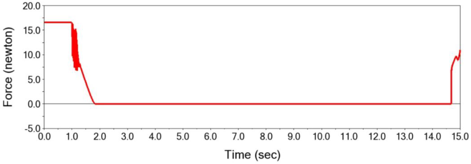
The contact force curve between hood and lower surface of housing.
The stress curve of the main spring is shown in Figure 13. At the beginning, the main spring is in the preload state, and the elastic force is stable at 25 N. It can be seen from the curve that the main spring vibrates slightly when the driving force is not enough to overcome the elastic force of the spring at the beginning, and then recovers to be stable. When the hood starts to move up slowly, the main spring is further compressed, so the elastic force is also gradually increasing. When the joystick moves to the limit position and stays for a period of time, it can be seen from the curve that the elastic force is in a stable state during this period. Later, when the hood moves downward, the compression of the main spring decreases, and the elastic force also becomes smaller and then gradually returns to the initial state.
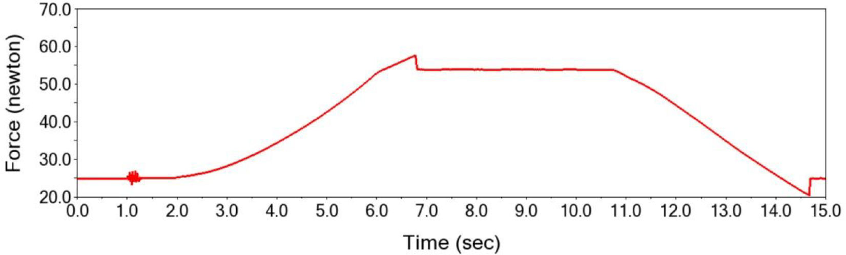
The force curve of the main spring.
It is the change curve of the motion angle of the joystick with time as shown in Figure 14. The angle at 6s is 10.81°, which is basically consistent with the previous 10.71° drawn by MATLAB within the allowable range of error. It also verifies the correctness of kinematic derivation. At the same time, it can be seen from the Figure 8 that the driving force F_1 has just reached the maximum value of 30 N in 6s, and the joystick still has a certain speed and does not reach a stable state. So, the angle ϕ does not stabilize at 10.71° but continued to increase. It was in a stable state at 6.78s. At this time, the rotation angle ϕ keeps unchanged and reaches the maximum value of 14.37°.

Diagram of ϕ with t in ADAMS.
Kinematics analysis and control simulation of driving simulator
This paper mainly uses Stewart six-DOFs platform to realize the synchronous movement of the control mechanism and the cab, so it is necessary to study kinematic derivation and overall simulation analysis for the six-DOFs motion platform.
Introduction to the helicopter driving simulator
For parallel mechanisms, there are many structural types. Some current parallel mechanisms are summarized systematically, and new parallel mechanisms and related control strategy research are proposed.
24
–26
Considering that in the driving simulator, the cab is directly above the parallel mechanism moving platform and the load is large, so the traditional 6-U
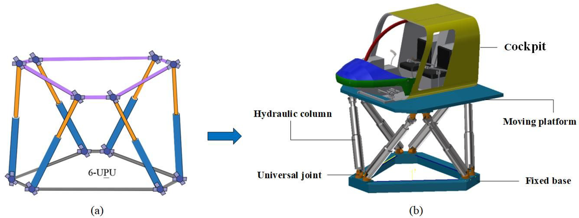
Structure diagram of driving simulator: (a) 6-U
The three-dimensional diagram of the helicopter driving simulator is built in SolidWorks and shown in Figure 15. The simulator is mainly composed by moving platform, fixed base, hydraulic columns, universal joints, cockpit, and other main components. The whole device is driven by hydraulic pressure.
Kinematic analysis of driving simulator
As shown in Figure 16, to analyze the kinematics of the driving simulator, the coordinate system A is established on a fixed base, and the coordinate system B is established on a moving platform. The coordinate origin is at OA
and OB
, respectively. The kinematic structure of each rod is an U
The position of the connection point on the fixed base and moving platform is represented by

Schematic diagram of six-DOFs platform mechanism.
The position of the center point of the moving platform is defined as

In addition, the rotation matrix is used to define the attitude of the moving platform relative to the base coordinates by using the Pitch–Roll–Yaw representation. Here,

where
In the control of driving simulator, it is mainly realized through the synchronous motion of manipulate mechanism and motion platform. It is the position diagram of the joystick around the rotation center as shown in Figure 17. The rotation angles of the joystick around the X, Y, and Z axes are

Rotation diagram of any position of joystick.
That is, the position and attitude of the motion platform are given, and the joint variable shall be solved by analyzing the inverse kinematic problem, 25 i.e.

From the geometry shown in Figure 16, the closed loop equation for each rod can be written as

where

Thus, the length of each rod can be uniquely determined by equation (18)

If the position and attitude of the motion platform are within the feasible domain of the manipulator working space, the rod length can be determined as one.
Kinematic model and joint simulation with manipulate mechanism
To directly observe the change process of the position and posture of the driving simulator under the control of the manipulate mechanism, the 3D model built in SolidWorks is imported into MATLAB/Simulink through a plug-in, the inverse solution module and controller of the parallel mechanism are designed, and a complete simulation model is built to achieve good visualization effect.
The overall control process Is shown in Figure 18.
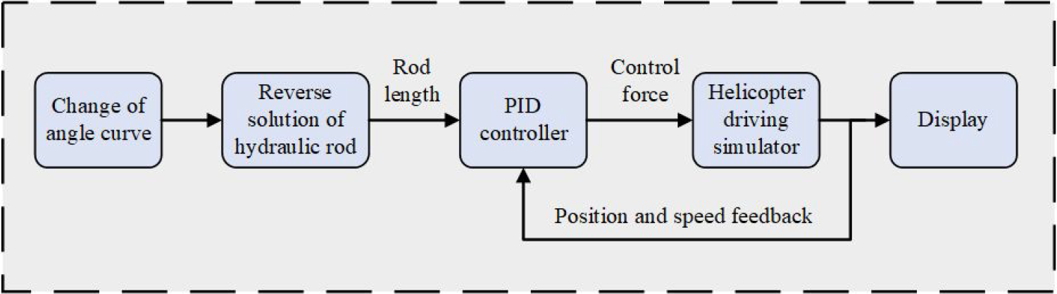
Control flow diagram.
The overall system block diagram built in Simulink is shown in Figure 19, which is composed of rod length inverse solution module, proportional-integral-derivative (PID) controller module, and platform model. Firstly, according to the expected trajectory of input, the telescopic amount of each hydraulic rod is calculated through the rod length inverse solution module [according to equation (18)], and then the telescopic amount is input into the PID controller. The output Simulink signal is converted into physical signal (i.e. control force) through the signal conversion module and inputted to the cylinder joint in the platform module to control the expansion and contraction of the hydraulic rod. At the same time, the position and speed signals of the hydraulic rod are input to the PID controller as feedback signals to achieve accurate control of the platform. In addition, the force condition of each hydraulic rod and the error curve of expansion and contraction can be observed in real time through the oscilloscope, which is convenient to adjust the parameters in the PID controller.

Helicopter driving simulator simulation system in Simulink.
The Simulink models of each subsystem are shown in Figure 20.
In Figure 20(d), Xang, Yang, and Zang are the rotation angles of the moving platform around the X, Y, and Z axes. Xpos, Ypos, and Zpos are the displacement of the moving platform along the X, Y, and Z axes, respectively.
Since the hydraulic rod is in the nontelescopic state in the initial state, the moving platform cannot change the position and attitude at this time. Thus, it needs to rise to a certain height first. As a solution, a rising curve can be given at the beginning as shown in Figure 21, the moving platform first rises from 1.45 m to 1.75 m within 0.15s along with the slope signal and then keeps the height unchanged. The joystick curve of angle change derived from ADAMS (as shown in Figure 14) is delayed for 15s, it means, the moving platform will not rotate within 0.15s. To simplify the research, only one of the rotation DOFs is controlled here. The angle curve is input into Yang, and the inputs of Xang and Zang are 0, it means, the moving platform will rotate around the Y axis with the joystick angle change curve to realize the synchronous movement of manipulate mechanism and helicopter driving simulator.

The Simulink models of each subsystem: (a) inverse solution module; (b) PID control module; (c) driving simulator model; and (d) input module.
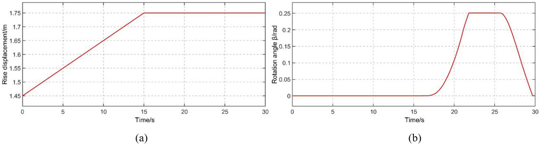
Input curves of system: (a) rise curve and (b) rotation curve.
Figure 22 shows the attitude diagram of the driving simulator when it rises to a certain height along with the input curve and then rotates to the maximum angle around the Y axis.

Maximum limit position diagrams in simulation: (a) maximum height and (b) maximum angle.
The control force curve of PID controller on each rod and the error diagram of each rod displacement are shown in Figure 23. From the images, it can be seen that at the beginning, the moving platform did not move according to the expected trajectory, and the control force output by PID controller and the rod telescopic error are relatively large, but they are quickly adjusted to the normal state. The control force and rod telescopic error slowly decrease to very small, basically maintaining a stable state.

The output curves of forces and errors: (a) curves of control forces and (b) curves of errors.
By connecting sensors to the moving platform, the displacement curve of the moving platform centroid relative to the base coordinate system and the angle change curve of the moving platform relative to the static platform are measured. As is shown in Figure 24 that the displacement curve and angle curve are measured by the sensor and the theoretical value of the angle change curve is compared with the actual value.

The curves obtained in the sensor: (a) displacement curve in X direction; (b) displacement curve in Y direction; (c) displacement curve in Z direction; and (d) comparison diagram of actual deflection angle and theoretical deflection angle.
From the curve comparison diagram in Figure 24(d), it can be seen that the trend of the theoretical value and the actual value are basically the same. At the beginning, because the control force output by the PID controller is not very stable, it can be seen that there is a small fluctuation in the figure, and then it gradually recovers to stability. The error at the maximum rotation angle is 0.45°, the error rate is 3.19%, and the synchronous simulation can be basically realized within the allowable error range.
From the simulation animation in Simulink, it can be observed that under the control of the mechanism, the helicopter driving simulator can basically follow its operation stably. It also verifies that the motion synchronization between the manipulate mechanism and the simulator is reasonable and feasible.
Conclusions
This study introduces a new manipulate mechanism with a self-reset function, which is based on a spring system integrated inside the joystick, designed to effectively simulate the load system of a helicopter driving simulator’s joystick. This design avoids the combination of traditional motors and complex control systems. Instead, it simulates the load on the joystick by setting spring parameters, making the structure simpler and more cost-effective. Additionally, the mapping relationship between the manipulate mechanism and the driving simulator is considered to keep their motions synchronized. After verifying the rationality of the manipulate mechanism’s design, the entire synchronized motion was simulated. The following conclusions were drawn: The integrated spring system of the new manipulate mechanism indeed enables a more effective simulation of the load system of the joystick in the helicopter driving simulator. The stiffness, free length, and preloading of the spring directly influence the force feedback and load perception of the joystick. By selecting appropriate parameters for the spring based on the desired loading force, better load simulation can be achieved, providing a more realistic operating experience. The design takes into account the mapping relationship between the manipulate mechanism and the driving simulator, ensuring that the motion of the manipulate mechanism remains synchronized with the motion of the driving simulator. This ensures that the motion and force feedback of the manipulate mechanism are consistent with the actions of the driving simulator, enhancing the realism and training effectiveness of the operation. The new manipulate mechanism can be applied in other teleoperation environments. In specific applications, different teleoperation environments may have various force requirements for the manipulate mechanism. Therefore, analyzing the force requirements of the system and selecting appropriate spring parameters are crucial. This ensures that the manipulate mechanism can effectively simulate the load in a specific teleoperation environment and provide accurate force feedback, thereby achieving a better teleoperation experience.
In the future, more tests and verifications will be conducted to further validate the reliability and performance of the manipulation mechanism, such as the response and force feedback under different speeds, angles, and load conditions.
Footnotes
Authors’ contributions
SY designed the mechanism and proposed the research method. ZW made theoretical analysis, software simulation and wrote the main manuscript text. MC and DZ made writing – review and editing. HY prepared the figures and tables. All authors have read and agreed to the published version of the manuscript.
Declaration of conflicting interests
The author(s) declared no potential conflicts of interest with respect to the research, authorship, and/or publication of this article.
Funding
The author(s) disclosed receipt of the following financial support for the research, authorship, and/or publication of this article: This work was supported by the Hebei Province Natural Science Fund, China (Grant No. E2019203431) and the Foundation for Innovative Research Groups of the Natural Science Foundation of Hebei Province, China (Grant No. E2020203174).