
Abstract
The existing deceleration systems in industrial robots often employ rotate vector (RV) or harmonic reducers to augment torque and decrease speed, yet achieving the motor’s peak power proves challenging. Given the extremely high space-size demands for reduction systems in robotic applications, an innovative compact continuously variable transmission is suggested, leveraging the transmission characteristics of spatial gear trains and metallic V-belts. The proposed system utilizes the input of an eccentric shaft to drive the planetary pulley’s rotation around the sun pulley. The pinhole, in cooperation with the eccentric shaft of the planetary pulley, achieves coaxial output of the transmission power. The article primarily explores the transmission and speed change mechanisms, then dissects the relationships between the transmission ratio and the effective radius of the pulley, the axial adjustment distance, and the factors influencing the pulley’s wrapping angle. Further, we use the Lagrange equation to derive the input equation, establishing the correlation between the planetary pulley’s rotation angle and system inertia, angular acceleration, angular velocity, and effective working radius over time. Finally, we simulate the continuously variable transmission’s motion to examine speed changes in forward, reverse, and neutral states. A continuously variable transmission prototype and a testing platform are also constructed to assess performance parameters, specifically input and output torque, and rotational speed.
Introduction
Continuously variable transmission (CVT) provides a continuum of gear ratios among the desired limits. This helps the engine to work in the optimum range for more time. 1,2 CVT is generally divided into three types: metal belt type, swing hinge type, and cone plate roller type. Among them, the metal belt type CVT is widely used to realize power transmission with conjunction of the solar and planetary gear. 3,4 Traditional transmissions have a relatively large volume and are mainly used in automotive transmission systems. In recent years, with the continuous embodiment of the advantages for CVT, they have also been increasingly applied in some lightweight robots, which can realize the continuous change of transmission ratio, making the motor and reducer better match. 5 –7 Given the smoothness of CVT transmission, researchers have improved its internal transmission structure to try it out in industrial and mobile robot. SRI International in the United States found that the energy efficiency of the robot at work is only 20% through the energy detection of the Proximi robot with fixed-ratio transmission. 8 Felton et al. proposed a passive wheel transmission and applied it to the joints of small robots, which show that the robot can passively adjust the transmission ratio according to the change of the external load to achieve the maximum utilization of the motor efficiency. 9 Mobedi and Dede produced a novel two-cone CVT whose design parameters are identified via carrying out a geometrical analysis. 10,11 Matsushita et al. proposed a load-sensitive CVT for wire-driven manipulators, which can realize power transmission by adjusting the transmission ratio with external mechanical structure. 12 Dresscher et al. developed a double-hemisphere CVT to improve the efficiency of the motor to 90%. 13 In addition, researchers have developed a variety of new CVT and tested their performance parameters for the application of special scenarios. Mobedi et al. introduced a new design method of double-cone CVT, which adopts double-sphere transmission element to determine the geometric dimensions and performance parameters. 10 Shin et al. presented a passively adaptable toroidal-CVT (pat-CVT) that is coupled with a twisted string actuator (TSA). The proposed combination of pat-CVT with TSA expands the operation range of TSA and mimics the torque–speed characteristics of artificial muscles. 14 Tran et al. introduced the first fully powered robotic knee prosthesis that matches the weight of state-of-the-art passive prostheses while providing suitable torque and speed to power ambulation on level ground and stairs. In addition, dynamic simulations are shown together with an extended experimental assessment supporting the design of a new actively variable transmission. 15 Meng et al. designed a high-power density variable transmission that enables continuous adjustment of the output speed to torque ratio. 16 Liu et al. studied the continuous geometric model of the metal V-belt and analyzed the kinematics and dynamics of a single metal segment. 17 Maleki et al. designed a CVT with metal push belt and variable pulley to replace its existing manual transmission system, according to the best efficiency curve of the engine to continuously match the engine power with the external load and eliminate the vibration caused by changing the transmission ratio. 18 Ji et al. studied the dynamics of power transmission of metal V-belt CVT in the micro and macro slip regions under external vibration conditions. 19 Based on CVT power transmission dynamics, a transmission simulator is developed to analyze the influence of slip on external vibration transmission characteristics in time and frequency domain. Wurm et al. developed a numerical model that can predict the thermal conditions related to the CVT and obtained the error sources mainly from the temperature of the pulley surface, the heat input of the belt, and asymmetric flow conditions. 20 –22 To explore a new type of CVT with high torque capacity and transmission efficiency, Chen et al. proposed a new type of wheeled CVT to transmit power through friction at the contact point between the input and the output disc. 23,24
From the above, although numerous analysis and verification have been carried out on the CVT used for robots, it is difficult to achieve small size and large transmission ratio due to its internal structure and transmission principle. It is an urgent problem to develop a CVT with compactness, lightweight, and large torque to adapt to the frequent changes in the direction, speed, and torque of robot joints. Therefore, a novel CVT with flexible metal V-belt is proposed based on the nested mechanism. By adjusting the effective radius of the solar and the planetary pulley, the transmission ratio of the CVT can be changed to meet the power requirements of the robot in real time. The organization of this article is given as: The first section presents the structural design, which encompasses the output mechanisms of the pinhole plate, the metallic V-belt, and the eccentric shaft. In the second section, the transmission mechanism is elaborated upon, along with an analysis of the geometric factors influencing the transmission ratio. The third section offers empirical verification of variable speed performance. Concluding remarks and prospects for future research are discussed in the final section.
Structural design
In a conventional CVT with a metallic belt, the axles of the sun and planetary pulleys are fixed. The effective working radius of the metallic belt is altered on the main and driven pulleys to modulate power output. However, this design has a limited range of transmission ratios and a larger overall size, rendering it unsuitable for robot transmissions that require larger transmission ratios, as depicted in Figure 1(a). The integration of a planetary gear train effectively addresses this issue by providing a high transmission ratio. As the planetary pulley revolves around the sun pulley, it undergoes self-rotation due to friction, as illustrated in Figure 1(b). By hypothetically reducing the length of the planetary carrier and increasing the diameter of the planetary pulley, a compact nested structure for the CVT can be developed.

CVT driving principle: (a) traditional CVT and (b) CVT with planetary carrier. CVT: continuously variable transmission.
Internal structure of the CVT
The innovative structure of the CVT lies in the eccentric integration of the planetary pulley within the sun pulley, with the metallic V-belt making friction contact with both pulleys. As the planetary pulley spins around its own axis, power is transmitted via the frictional contact with the metallic V-belt, even as it orbits the sun pulley. As shown in Figure 2, the CVT primarily consists of components such as the sun pulley, planetary pulley, metallic V-belt, eccentric shaft, pinhole plate, input shaft, output shaft, frame, and a hydraulic device. Both the planetary and sun pulleys comprise left and right halves, with axial motion between them facilitated by the hydraulic device. The center of the planetary pulley is linked to the eccentric shaft through bearings, and the metallic V-belt is installed under tension between the sun and planetary pulleys. Rotation of the planetary pulley around the sun pulley is made possible by the eccentric shaft’s rotation. The CVT’s output end is linked via a pinhole, and the output end’s conversion is achieved through the pin shaft’s rotation on the planetary pulley within the pinhole plate. This effectively ensures concentricity between the input and output shafts and maintains transmission stability. Additionally, hydraulic device allows for adjustment of the lateral distance between the sun and planetary pulleys, enabling the alteration of the transmission ratio to achieve different output speeds.

Composition of the CVT system. 1—motor; 2—motor bracket; 3—input shaft bearing; 4—input end panel; 5—right solar pulley; 6—hydraulic cylinder barrel; 7—limited rod; 8—hole seal ring; 9—shaft seal ring 1; 10—piston rod; 11—linear bearing; 12—metallic V-belt. 13—shaft seal ring 2; 14—cylinder head; 15—left solar pulley; 16—output panel; 17—output bearing; 18—output shaft; 19—pin sleeve; 20—pin; 21—output adapter plate; 22—output plate; 23—left planetary pulley; 24—eccentric shaft; 25—right planetary pulley.
Output mechanism of pinhole plate
The pinhole plate output mechanism consists of four equally divided holes with diameter of d 1, shown in Figure 3. At the output end of the planetary pulley, four dowels with diameter d 2 are equally arranged along the circumference of the center with diameter D, which is sleeved with a rotatable dowel sleeve. Through the revolution and rotation between the pin and the pinhole, the pinhole plate will concentrically output the power. The eccentricity between the planetary pulley and the output disc is H, then, d 1 − d 2 = 2H. O 1 O 2 always parallel to O 3 O 4 in the process of motion, so the motion of pinhole output is completely equivalent to parallelogram mechanism which has the advantages of compact structure, high reliability, low friction loss, and convenient manufacturing.

Output mechanism of the pinhole plate.
Metallic V-belt
The design of the metallic V-belt is critical to the transmission system’s efficiency. The primary challenges lie in the installation of the metallic sheets and the fabrication of the metallic ring. As depicted in Figure 4(a), the metallic V-belt has an overall trapezoidal structure, comprising multiple metallic sheets with symmetrical clamping slots. As shown in Figure 4(b), the metallic sheet has a bottom width of 8 mm, a height of 18 mm from the bottom to the clamp slot, a thickness of 2 mm at the bottom, and a top width of 4 mm. The series connection consists of a metallic ring made from stainless steel, known for its exceptional toughness and extraordinarily high bending resistance cycles. Both ends of the metallic ring, which is 0.2 mm thick, are bonded together using a full welding process.

Metallic V-belt: (a) assembly drawing and (b) metallic sheet.
Eccentric shaft
The input end of the eccentric shaft is connected with the motor, and the output end is joined with the planetary pulley through the bearing. Under the rotation of the eccentric shaft and the action of the metallic V-belt, the planetary pulley realizes rotation and revolution around the solar pulley. If the balance mass of eccentric shaft is not considered, it will cause large vibration and noise.
The vector expression for the static balance condition of the eccentric shaft is

where
Substituting quality elements, equation (1) can be transformed as

Eliminating the angular velocity ω can obtain

where
The initial eccentric distance between the eccentric journal and the rotation center is set at 5 mm, and it is composed of multiple cylindrical elements and several chamfers. The solid mass of the eccentric journal is 26.75 g, and the mass-diameter product amounts to 133.75 g·mm, as displayed in Figure 5(a). To avoid stress concentration and generate a larger inertial force, the eccentric shaft’s mass is uniformly adjusted, reducing the balance weight on the eccentric side and expanding the axial dimensions. Using equation (1), we find the mass-diameter product of the eccentric shaft to be 64.232 g·mm, with a balance weight of 12.95 g and a vector diameter of 4.96 mm, as shown in Figure 5(b).

Eccentric shaft structure: (a) before optimization and (b) after optimization.
Transmission mechanism
Transmission ratio
The transmission ratio is the CVT’s most crucial parameter as it influences the output torque. It is derived from the rotational geometry kinematics of the sun and planetary pulleys. The transmission system comprises four components: the sun pulley, the planetary pulley, the planet carrier, and the metallic V-belt, as depicted in Figure 6. The sun pulley is stationary, whereas one end of the planet carrier can rotate around the sun pulley’s axis, and the other end connects to the central axis of the planetary pulley. The metallic V-belt meshes with the solar pulley and the planetary pulley. When the planet carrier rotates, the planetary pulley does the revolution and rotation movement under the power transmission of metallic V-belt. Therefore, the power generated by the rotation of the planetary pulley is just the output of the CVT. R 1 and R 2 represent the effective working radius of planetary pulley and solar pulley, respectively. This transmission mode can be described as the planetary pulley with an effective working radius R 1 rotates around the center point O of the solar pulley with an effective working radius of R 2 and rotates around its own axis. The solid line indicates the initial state. When the planet carrier rotates through angle β 2, the rotation output angle of the planetary pulley is β 1. At this time, the position of the space between the two pulleys is shown in the dotted line. The output angle β 1 and the input angle β 2 are specified to be positive in the same direction and negative in the opposite direction. Assuming that the V-belt does not slip, now take four points a, b, c, and d on the belt, a and d represent the vertical reference point respectively. b and c represent the tangent point of the belt and the two pulleys respectively. Both points b and c have an included angle α with the horizontal direction. The belt at point d in the initial state of motion has not yet separated from the pulley. Taking four points a′, b′, c′, and d′ on the belt, the points a′ and d′ represent the spatial position of points a and d in the initial state of the belt respectively. β 1 is the output angle between a′ and vertical direction. d′ point coincides with the d, and the b′ and c′ respectively represent the tangent point of the belt and the two pulleys.

Transmission schematic diagram.
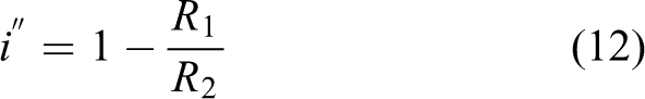
Through the geometric relationship in Figure 6, it can be obtained as


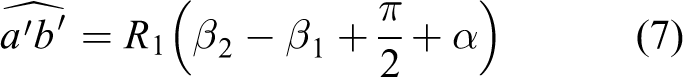


Substituting equations (6) to (9) into equation (4), the transmission ratio i of the CVT can be obtained as
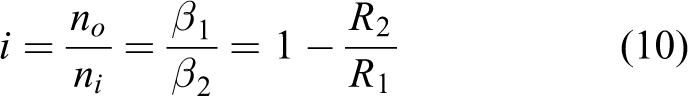
Equation (10) reveals that the transmission ratio i is solely related to the effective radii of the sun and planetary pulleys. By referring to the effective radii R 1 and R 2, we can depict the output condition of the CVT, as shown in Table 1.
The output status of the CVT.
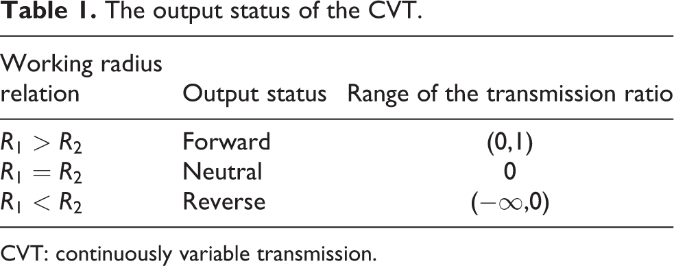
CVT: continuously variable transmission.
When the planet carrier is fixed and the pulley with effective working radius of R
2 is the driving pulley, meanwhile the pulley with effective working radius of R
1 is the driven pulley, then the transmission ratio
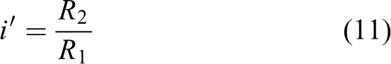
However, when the pulley with an effective working radius of R
1 is restricted in rotational freedom, the planet carrier is the driving part, and the pulley with an effective working radius of R
2 is the driven pulley, the transmission ratio
The following study is only carried out for the transmission ratio shown in equation (10).
Warping angle
The transmission principle of the CVT is essentially similar to that of belt, so the size of the wrapping angle directly affects the friction between the pulley and the V-belt, which directly affects the output torque. As shown in Figure 7, δ 1 and δ 2 represents the warping angle of planetary pulley and solar pulley respectively, and the following relationship can be obtained


The mechanism of variable speed.
In the neutral position of the CVT, the effective working radius of the planetary pulley is specified as R 0, which is the same to the one of solar pulley. Therefore, we can conclude that

Equation (13) can be converted to
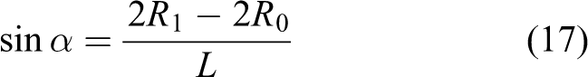
Therefore, the wrapping angles of the two pulleys can be obtained as

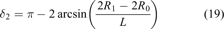
At the extreme position of forward output, the equation R 1 = R 0 + L/2 holds true, yielding a maximum δ 1 value of 2π and a minimum δ 2 value of 0. This illustrates that the operational radius of the sun gear is entirely encompassed by the planet gear. In a neutral state where R 1 = R 0, both δ 1 and δ 2 equal π, suggesting that the effective working areas of the sun and planet gears are equal. Conversely, in the extreme position of reverse output, δ 2 reaches its maximum value of 2π while δ 1 is at its minimum of 0, indicating that the operational radius of the planet gear is fully enveloped by the sun gear.
The warping angle constantly changes throughout the process of speed regulation, which concurrently results in a variation in the pitch length. The pitch lengths at the limit position of forward output, neutral output, and the limit position of reverse output are represented by C 1, C 2, and C 3 respectively and are defined as follows:


As the pulleys of the CVT transition from the forward limit to the reverse limit position, the pitch line length of the metallic V-belt evolves in the sequence: C 1→C 2→C 3. Given that the V-belt’s pitch line length is identical at both limit positions, its transformation involves an initial decrease followed by an increase, with the maximum difference being (π − 2)L. Hence, for optimal transmission performance, it is crucial to ensure that the metallic V-belt is properly pretensioned and preferably elastic. This will counteract potential slack in the pulley due to the variations in the pitch line length.
Variable speed mechanism
The effective radii of the sun and planet gears dictate the magnitude of the transmission ratio. This can be varied by splitting each of the sun and planet gears into two symmetrical components and altering the distance between these pairs. The working principle is as follows: The CVT’s sun and planet gears each consist of two corresponding semi-pulleys, as depicted in Figure 7. These four semi-pulleys are numbered from 1 to 4, from left to right. Numbers 2 and 3 form the planet gear, while numbers 1 and 4 constitute the sun gear. Semi-pulleys 1 and 3 are capable of axial movement, while semi-pulleys 2 and 4 are axially fixed. In addition, semi-pulleys 1 and 4 have restricted rotational freedom, while semi-pulleys 2 and 3 are able to revolve around their respective axes. In Figure 7(a), the planetary pulley is nested in the solar pulley, and their axes are on the same line. The inside and outside of the metallic V-belt are in static friction contact with the planetary and solar pulley respectively. Since the pitch line position of the metallic V-belt will not change, the planetary and solar pulleys have the same effective working radius under this working condition. The transmission mode of the transmission is similar to the planetary gear train. Therefore, the axis of the solar and the planetary pulley should be separated during operation, as shown in Figure 7(c), then there will be an eccentricity between the planetary and solar pulley, however, they still have the same effective working radius illustrating that the transmission i = 0, which show that the working state of the CVT is the neutral state. In Figure 7(c), the half pulleys 1 and 3 move to the left simultaneously, and the half planetary pulleys on both sides are close to each other, which give rise to being squeezed of the V-belt away from the solar pulley, up to the working state shown in Figure 7(b). The inner part of the V-belt on the solar pulley is in contact with the planetary pulley, which prevents the half pulley 3 from moving to the left and reaching the leftmost limit position. In this process, the effective working radius of the planetary pulley is greater than that of the solar pulley, which indicates the transmission ratio i > 0, and then the transmission’s working state is positive output. The half pulleys 1 and 3 in Figure 7(c) moves to the right, then the two sides of the planetary pulley are far away from each other, which lead to sliding downward for V-belt and being close to each other for the solar pulley, shown in Figure 7(d). The outer part of the V-belt on the planetary pulley is in contact with the solar pulley, which prevents the half pulley 1 reaching the rightmost limit position. During right process, the effective working radius of the planetary pulley is smaller than that of the solar pulley, so the transmission ratio i < 0, showing the working state of the transmission is reverse output.
When half pulleys 1 and 3 move to the left limit position, shown in Figure 7(b), the effective working radius of metallic V-belt on the planetary pulley is
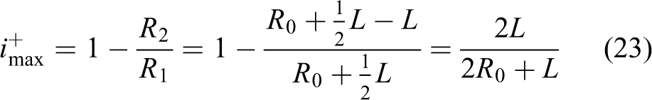
Correspondingly, when half pulleys 1 and 3 move to the right limit position shown in Figure 7(d), the effective working radius of V-belt on the solar pulley is
Therefore, the range of transmission ratio can be obtained as
Geometric parameters of transmission ratio
When the two halves of the pulley either diverge or approach each other, the effective working radius undergoes real-time changes, thereby resulting in adjustments to the transmission ratio. During this alteration of the semi-pulley’s position, the V-belt is either compressed or allowed to slide downward. This causes the effective position of the V-belt on the pulley to either ascend or descend, as depicted in Figure 8. Assuming that the displacement of the semi-pulley in relation to the neutral position is Δd, and the vertical change in the V-belt position is ΔR. Moreover, the angle created by the two halves of the planetary pulley is 2θ. With these conditions, we can establish the following correlation between the vertical variation ΔR and the axial displacement Δd
Geometric parameters of transmission ratio when the half pulley moves.
The change

Consider the symmetrical center of the half pulley as the origin of the coordinates in the neutral position, with the rightward movement of the pulley representing the positive direction on the horizontal axis. Meanwhile, the upward movement of the metallic V-belt corresponds to the positive direction on the vertical axis. In this case, the effective working radius of the V-belt is R 0, and the distance d is 0. The maximum displacement of the semi-pulley is |L tan θ|. Therefore, the relationship between the effective working radius R 1 on the planetary pulley and the displacement d is as follows

The pitch line distance from the planetary to the solar pulley is 2R 0 + L. So the relationship between the effective working radius R 2 of the solar pulley and the moving distance d is

Therefore, the function of the transmission ratio relative to the moving distance and the included angle of the half pulley can be deduced as follows

Since equation (30) is relatively complex, the range of transmission ratio is only carried out under the following conditions: R 0 = 35 mm, L = 5 mm and θ ∈ (π/6, π/3), d ∈ (−5 tan θ, 5 tan θ), shown in Figure 9. With the increase of the included angle θ between the half pulley and the vertical direction, the moving distance d will also increase proportionally. However, the change of θ does not affect the range of the transmission ratio i. As mentioned above, the transmission ratio is only related to the eccentricity L and the effective working radius R 0 of the planetary and solar pulley in the neutral position.

The relationship of the transmission ratio i relative to the moving distance d and the included angle θ of the half pulley.
Dynamic analysis of the CVT
Establishing a polar coordinate system at the center of the solar pulley, the mass distribution of kinematic chain is shown in Figure 10. The system inertia and the planetary pulley relative to the center are JO
and


Mass distribution diagram of kinematic chain system.
The kinetic energy T of the system can be obtained as
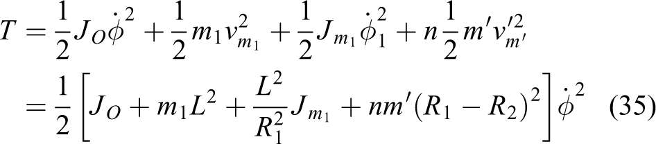
Generalized force is as follows

According to the Lagrange equation, we can obtain

Therefore, the angular acceleration of the planetary pulley is shown as

Finally, the input motion equation of the system can be calculated as

Simulation and experiments
Kinematic simulation
The accuracy of the derived transmission ratio was validated using multi-rigid-body dynamics simulation software, and the simulation was performed under conditions without gravitational influence. At 0s, the speed of the drive shaft is 0 deg/s, transitioning linearly to 1000 deg/s at 0.5s, and maintaining this speed from 0.5s to 3s. Figure 11 illustrates the speed variation curve of the output shaft during forward, neutral, and reverse states. The parameters and simulation outcomes for the planetary pulley, sun pulley, and eccentricity are presented in Table 2. In the forward state, the theoretical output speed is 116.3 deg/s, and the simulation output speed is 114.1 deg/s, resulting in a relative error of 1.89%. In the neutral state, both the theoretical and simulated values are 0. In the reverse state, the theoretical output speed is 46.5 deg/s, and the simulated output speed is 44.7 deg/s, resulting in a relative error of 3.87%. These findings demonstrate a close approximation between the theoretical predictions and the simulation results. The minor discrepancy is attributed to the consideration of speed in the initial state during calculations.

Output speed in forward, reverse, and neutral states.
The performance parameters of CVT.

CVT: continuously variable transmission.
Manufacture of the principle prototype
The critical components of the CVT are crafted using high-precision machining techniques. The casing and the metallic sheet are constructed from aluminum-magnesium alloy 7075, while the eccentric shaft and pinhole plate are made from 45# steel. The metallic ring is composed of stainless steel 304. By inserting the metallic V-belt into the outer periphery of the sun and the planetary pulley and integrating other essential components, we achieve the principle prototype of the CVT. The prototype’s maximum diameter is 125 mm, the height is 98 mm, and it weighs 7.5 kg, as depicted in Figure 12.
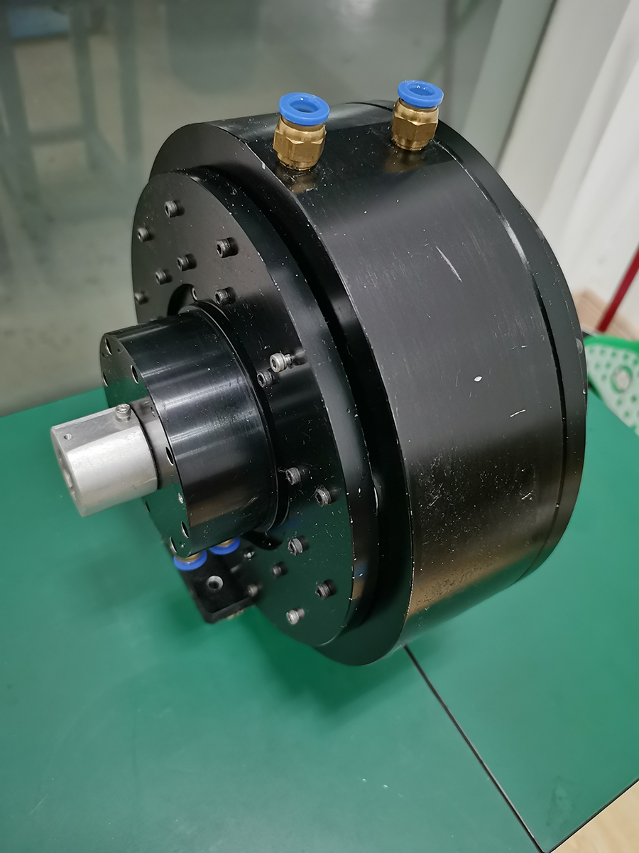
Principle prototype of CVT.
Performance testing
The CVT testing platform chiefly comprises a torque sensor, a magnetorheological damper, profile support, and motor torque display software and hardware, as illustrated in Figure 13. The torque sensor is utilized to measure the output shaft’s torque. The magnetorheological damper supplies varying loads to the CVT by adjusting the current, while the profile bracket serves to support the system components of the test platform. The motor torque display software and hardware are employed to provide real-time visual representation of the motor’s torque.
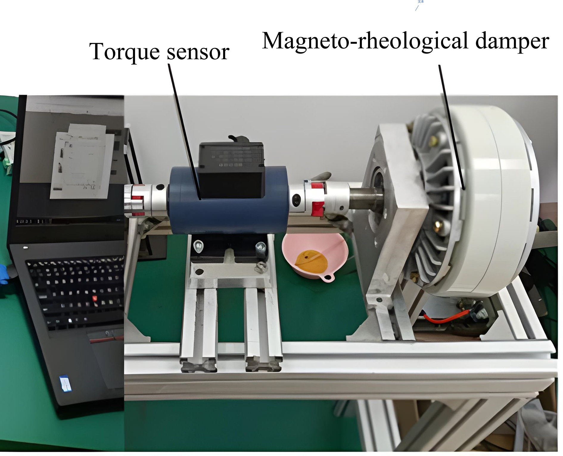
Testing platform.
In the forward transmission state, the value of magnetorheological damper is set to 6 N·m. When the transmission ratio is 0.02, 0.03, and 0.04, the input torques of the CVT are 0.15 N·m, 0.26 N·m, and 0.36 N·m respectively, shown in Figure 14. So the transmission efficiency can be deduced to be about 72%.

Forward input torque when transmission ratios are 0.02, 0.03, and 0.04 respectively (output torque is set to 6 N·m).
In the neutral state, the output torque of the CVT is set to 0.2 N·m, 0.3 N·m, and 0.5 N·m through the magnetorheological damper, the input torque is measured to be about 0.05 N·m, shown in Figure 15. The reason why the input torque is not 0 is that the transmission is affected by friction during rotation.

Input torque of the CVT at neutral state (output torque is set to 0.2 N·m, 0.3 N·m, and 0.5 N·m respectively).
In the reverse transmission state, the output torque is set to −5 N·m. Then, the input torque is measured to be 0.12 N·m, 0.2 N·m, and 0.28 N·m, when the transmission ratio is set to 0.02, 0.03, and 0.04 respectively, shown in Figure 16. Therefore, the transmission efficiency is deduced to be about 70.5%.

Reverse input torque when transmission ratios are 0.02, 0.03, and 0.04 respectively (output torque is −5 N·m).
Moreover, the input speed and transmission ratio are preset to 1000 r/min and 0.03 respectively. In the forward, neutral, and reverse states, the output speeds are accordingly 30.5 r/min, 0.1 r/min, and −28.2 r/min as depicted in Figure 17. Judging by the relationship between the input and output speeds, experimental results align closely with both the theoretical predictions and simulation data.

Output speed of the CVT (transmission ratio is 0.03 and input speed is 1000 r/min).
Conclusion and future work
Based on a nested mechanism, a configuration scheme for an innovative embedded CVT has been proposed. The eccentric shaft, metallic V-belt, and pinhole output mechanism have been primarily analyzed. The transmission mechanism of the CVT has been deduced, and the relationship between the transmission ratio and the effective radius of the planetary and solar pulleys has been determined. Furthermore, the range of variation in the pulley warping angle has been deduced. The transmission mechanism has been analyzed to identify the geometric factors that influence the transmission ratio during axial movement of the solar and planetary pulleys. A comparison between the theoretical values and actual measurements reveals a forward deviation of 1.89% and a reverse deviation of 3.87% in transmission. Finally, a principle prototype and a testing platform have been separately manufactured to measure the input torque and output speed in the forward, neutral, and reverse states. Moving forward, it is necessary to optimize the overall structure of the CVT to accommodate the requirements of robots of different sizes. Additionally, a life cycle analysis of elastic materials for V-belts will be conducted, along with further analysis of adaptive control for hydraulic adjustment devices to meet the speed ratio and torque requirements of robots.
Footnotes
Declaration of conflicting interests
The authors declared no potential conflicts of interest with respect to the research, authorship, and/or publication of this article.
Ethical statement
I testify on behalf of all co-authors that our article submitted to International Journal of Advanced Robotic Systems.
(1) This material has not been published in whole or in part elsewhere;
(2) The manuscript is not currently being considered for publication in another journal
(3) All authors have been personally and actively involved in substantive work leading to the manuscript, and will hold themselves jointly and individually responsible for its content.
Funding
The authors disclosed receipt of the following financial support for the research, authorship, and/or publication of this article: This work was supported by grants from Natural Science Fund of Jiangsu Province (BK20220241), General project of Natural Science Foundation of colleges and universities of Jiangsu Province (21KJB460006), Changzhou applied basic research project (CJ20220181), Changzhou leading innovative talents introduction and cultivation project (CQ20210079). Philosophical and social science research projects in universities in Jiangsu Province (2023SJYB1348).