
Abstract
Climbing robots play an essential role in performing inspection work in civil infrastructures. These tasks require autonomous robots with competitive costs and the ability to adapt to different types of environments. This article presents ROMERIN, a new concept of a modular legged climbing robot where each leg is an autonomous robotic module in terms of processing capacity, control, and energy. The legs are equipped with suction cups that allow the robot to adhere to different types of surfaces. The proposed design allows the creation of climbing robots with a different number of legs to perform specific inspection tasks. Although each of the legs acts as an independent robot, they have the ability to share information and energy. The proposed control concept enables the development of climbing robots with the ability to adapt to different types of inspection tasks and with resilience characteristics. This article includes a description of the mechatronic design, the kinematics of the seven degree-of-freedom robotic legs, including the adhesion system, and the architecture of the control and simulation system. Finally, we present experimental results to test the modularity concept, mechanical design, and electronics using a four-legged robot configuration. We analyze the performance of the gripping system in different situations on four different surfaces and the behavior of the control architecture for two different robot body trajectories.
Introduction
Due to aging, environmental factors, damages caused by human or natural factors, inadequate or poor maintenance, and deferred repairs, civil infrastructure is progressively deteriorating. Therefore, civil infrastructure, such as buildings, tunnels, bridges, and large industrial facilities, must be regularly inspected and maintained to assess and ensure their long-term viability and safety. The current conventional inspection methods are risky to operators, and the reliability and consistency of these processes reveal substantial variability in both the quality and quantity of the resulting assessments. 1 Accidents with serious consequences, such as the one that occurred on the Morandi Bridge in Genoa in 2018, have highlighted the fact that these tasks are not always carried out with sufficient guarantees.
In recent years, great effort has been made to develop inspection robots, including ground-based robots, crawling and climbing robots, and unmanned aerial and marine vehicles. 2 These robotic systems are equipped with onboard inspection sensors, such as NDE systems. Robots can contribute to lower-cost inspections, increasing the reliability of the evaluations obtained and minimizing the risks to operators. 3 However, there are important barriers to be lowered so that robots can be used massively for inspection tasks. Robot designs must take into account critical aspects such as autonomy, as well as robust locomotion and navigation appropriate for inspection work, which typically must be done in complex, nonstructured, and exposed outdoor environments. All these challenges mean that it is not possible to develop a unique robot capable of completely replacing conventional inspection systems, but that it is necessary to develop different types of robots adapted to specific inspection tasks. Autonomous robots are still challenging, especially in civil infrastructure environments, where hazards and obstacles are frequent and unpredictable. For this reason, although there are some exceptions, most of the existing inspection robots are teleoperated.
In this article, a new concept of a fully modular autonomous legged climbing robot design, called ROMERIN, is presented. The robot is able to adapt its characteristics to move in complex environments with vertical surfaces and even ceilings and can carry navigation and inspection equipment such as 3D cameras or LIDAR, and NDT equipment such as ultrasonic sensors and penetration georadars to perform inspection tasks. A suction cup, equipped with its own turbine to create the vacuum needed to ensure the adhesion of the robot, has been specifically designed and installed in each leg. The robot is modular from the point of view of the mechatronic design concept, since each of the legs has been designed as an independent robot but with the ability to share information and energy. A modular control system has been designed to test the modularity concept, the mechanical design, and the electronics. To do so, a hierarchical centralized control architecture, based on behavior, has been designed and made up of various modules that allow the robot to be controlled independently of the number of legs and existing actuators. This architecture has been structured in three levels and is presented in this article.
The motivation of this work stems from the search for a versatile system capable of inspecting a large number of civil infrastructures that are difficult to access. For this reason, an adaptable system with the capacity to carry different tools was proposed. This implies that the system has to be able to accommodate different payloads and layouts. The solution presented in this work consists of a robot in which the body has attached legs that are autonomous robotic modules. In this way, an organism is obtained in which the number and arrangement of the legs can be varied according to the needs of the application. Although each module has enough autonomy to manage its own actuators and sensors, there is a main “brain” that coordinates all of them. This facilitates the design of a flexible central control, although the correct coordination of the different modules becomes complex. In addition, a smart energy system has been designed to provide a robust solution to failures. Each module has its own battery and the electronics necessary to be able to obtain or supply energy from the rest of the robot modules. Moreover, by providing each module with its own battery, the autonomy of the robot does not vary substantially if the number of modules increases, as the autonomy is determined by the battery of each module. ROMERIN is the evolved and modular version of the ROMHEX hexapod climbing and legged robot. 4 However, in this case, the robot mainly develops the concept of modularity, resilience, energy sharing, and adaptability.
The following section presents a state-of-the-art of modular and climbing legged robots. This is followed by a presentation of the mechatronic development of a leg as an independent robot and the developed control and simulation system. Finally, some experimental results and conclusions are presented.
State of art
In recent years, a considerable number of climbing robots have been developed using various technologies and approaches. 5,6 These robots could be clearly differentiated based on two principles: the type of locomotion on which they are based and the adhesion system used. Regarding the adhesion system, most climbing robots are based on the use of negative pressure vacuum or propeller systems, 7 –9 on magnetic adhesion in the case of working on metallic structures, 10 –13 or on mechanical. There are other adhesion technologies, such as elastomer 14,15 and electrostatic. 16,17 Each adhesion technology has its own characteristics and limitations, being suitable or not suitable for use depending on the requirements and conditions of the material or surface. 18 Although magnetic adhesion is reliable and has low energy consumption, it can only be used on ferromagnetic surfaces and is not allowed for detection equipment. Elastomer and electrostatic adhesion technologies can be used on different surfaces, but their reliability and payload capacity are limited. Vacuum adhesion can also be applied on different materials, and if the vacuum is well maintained, it is reliable, allowing the transport of detection equipment. The main drawback of vacuum technology is high energy consumption. Vacuum adhesion has been successfully applied to a number of window cleaning robots. 19 –21
The Magneto robot 22 is an example of a magnetic adhesion climbing robot, and it has some similarities with the proposed ROMERIN robot in the kinematics and in some of the design concepts, such as the three degrees of freedom compliant foot. Other example of magnetic adhesion is found in Peidró et al., 23 where the authors present magnetic grippers for the HyReCRo robot, which is a biped robot that can climb and explore steel structures. The peculiarity of this approach is that each gripper carries three switchable magnets that, depending on their relative orientation to each other, can attach or detach from the ferromagnetic substrate. Eto and Asada 24 present a wheeled wall-climbing robot with a shape-adaptive magnetic adhesion mechanism for large steel structures. They designed a rotational mechanism installed in each wheel to vary the orientation of the magnets to keep the magnetic force direction normal to the surface. Seriani et al. 25 present the modeling and validation of a new family of climbing robots that are capable of adhering to vertical surfaces through permanent magnetic elements. The approach achieves climbing capabilities even on nonferromagnetic and curved surfaces.
Mechanical adhesion is gripper-based and its range is very limited due to the environments on which they are focused. In fact, its use has been noticeably neglected. Among others, ROMA I 26 and LIBRA 27 use this type of adhesion. On the other hand, for environments such as architectural infrastructures, pneumatic adhesion is the most attractive because of its versatility. Within this group, we find those who use passive suction cups, 28,29 vacuum chambers, such as Alicia 3, 30 or the one presented in literature, 24,31 and suction by vacuum generation. 32 This last type is used in our approach because of its compactness, versatility, simplicity, adaptability, and suitability for variable environments. Also worth noting is the recent proliferation of electrostatic systems, based on gecko mimics, 33 or micro spines, employing a variety of miniature spines that catch on surface roughness 34 or dry adhesives. 35
With respect to the type of locomotion, the main challenges are stable climbing ability and overcoming obstacles. Wheeled mechanisms, such as presented in Papadimitriou et al. 36 and Koo et al., 37 are fast and stable but have many difficulties in overcoming obstacles. Legged walking robots are not as fast and have to cope with locomotive stability. However, this type of robot is very well suited to overcome obstacles and move in complex structures such as civil infrastructures. Legged and climbing robots with few degrees of freedom have difficulty changing from one plane to another. Increasing this number leads to higher complexity but also to more flexibility and climbing capabilities.
There are also many designs of climbing robots for the purpose of carrying out specific tasks in civil infrastructures. These tasks may be risky for human operators or may require a high level of precision, for example
38
: Inspection of wind generators in operation Cleaning of windows in large buildings Analysis of aircraft fuselages and ship hulls Revision and dismantling of nuclear power plants Inspection of large buildings, tunnels, cooling towers, and large infrastructures.
Most modular robots can be reconfigured to be able to perform different tasks or gaits. In reconfigurable modular robots, modules must be as autonomous as possible, including mechanical, electrical, powering, and control autonomy. 39 Most robotic modules have this modularity in each module, but one important characteristic in modular reconfigurable robots is the possibility of cooperation among modules to achieve certain tasks. For example, to perform different locomotion patterns, or in case of failure of one module, perform its tasks. Mechanical, electrical, and control cooperation has already been achieved. Mechanical, in the sense of cooperation in locomotion. Electrical, in the sense of communication between modules. Control, in the sense of distributed computing and decision taking. But in power sharing among modules, there is still a lot of work to do.
At present, most modular robots use tethers or its own batteries, mainly lithium-polymer and lithium-ion. 40 Power sharing was first mentioned in Atron modules, 41 but more like a power distribution line. Humza et al. 42 present the concept of “energy homeostasis” (Symbricator Project) in an artificial robotic organism, as a process that regulates the energy or power flow between the modules of the system to achieve self-sustainability for longer periods of time without human intervention. Power sharing was first described in Qadir, 43 and recently in Chen et al., 44 where a similar approach is explained in the simulation for the Superbot modules. Legged robots where each leg is a module are difficult to find. Hayakawa and Matsuno 45 present “KARAKASA,” a reconfigurable modular nonclimbing robot, where each leg has its own electronic board to manage its motion and monitor the failure risk. Although this robot is simpler than ROMERIN from a mechanical point of view, it demonstrates great capabilities against module failure during walking, although it does not provide power sharing capabilities.
The proposed ROMERIN robot concept has been designed to be completely autonomous and to achieve mechanical, electrical, powering, and control cooperation between modules, including power sharing, in a fully modular way. It is a legged climbing and walking robot that uses specifically designed vacuum adhesion technology. By having an adhesion system based on vacuum generation, our system is capable of climbing in a large number of environments, such as magnetic infrastructures, places where it is desirable not to generate a magnetic field, civil infrastructures, wind turbines, cooling towers, and so on. Unlike other climbing robots, vacuum is generated in each module independently, so the modules are responsible for managing the tool. Similarly, high-level control delegates the low-level management of the modules to the electronic onboard of the modules.
Mechatronic development of the robotic leg
Modularity concept
The concept of ROMERIN as a fully modular climbing robot is based on the design and development of a leg that is by itself a complete and autonomous robot but has the ability to share energy with the rest of the legs. The adhesion system, which is described later in this section, is based on the placement of a suction cup at the end of each of its legs. Figure 1 shows two different possible robot configurations using four and eight robotic modules (legs), respectively.

Romerin modular robot four-legged and eight-legged configurations.
Each of the legs (see Figure 2) is equipped with the following elements: A dedicated microcontroller for control. Specific electronics for robot instrumentation. The leg is able to properly distribute, in voltage and current, the energy to the different components and other modules. A battery that allows it to operate autonomously. A completely self-contained actuation system. A module itself is capable of moving under nominal conditions. Communication with other modules and with the outside. A sensorized suction cup with a vacuum turbine to adhere the leg to the surface.

ROMERIN robotic leg.
Therefore, the robotic leg module is a robot by itself. It is a completely autonomous basic unit. It is able to move and manage its own resources. However, it is also prepared to collaborate with other robotic leg modules. Through the communication system, it can deal with requests from the outside and also coordinate its actions to be able to walk or climb with the help of other modules. Its design is capable of contributing to the mechanical task of the whole and, if necessary, even providing the energy required for it.
Mechanical design
The robotic module has been designed with seven degrees of freedom disposed as follows (see Figure 3): 3 power servomotors on the shoulder (q1, q2, and q3). 1 power servomotor at the elbow (q4). 3 servomotors of orientation in the wrist (q5, q6, and q7).
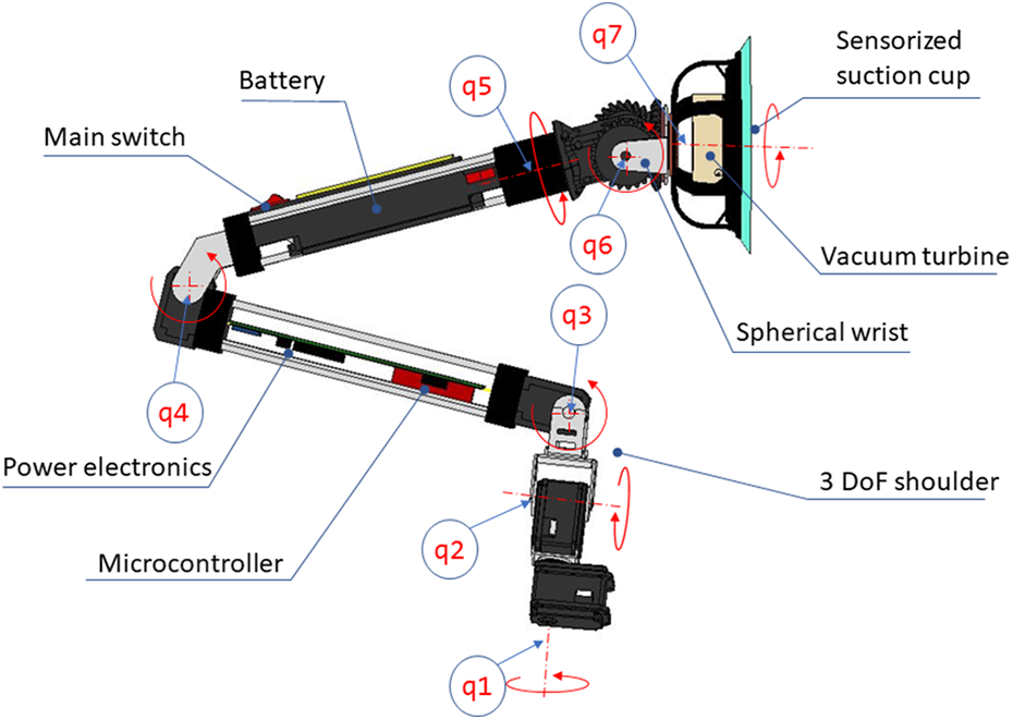
ROMERIN robotic leg kinematics.
This structure is the result of adding to the kinematic configuration of four degrees of freedom for the leg proposed by the most agile walking robots the two degrees of freedom necessary to be able to orient the plane of the suction cup located at its end.
Due to their compact and smart actuator characteristics, DYNAMIXEL servomotors were chosen. DYNAMIXEL servomotors provide feedback of position, velocity, intensity, and so on. Powerful servomotors have been used in the shoulder and elbow, as they are responsible for achieving the movement of the robot. The module uses a 9.9 Nm stall torque servo (XH540-W270-T) in the first and third articulations and 6.4 Nm servos (MX-64) in second and fourth. However, on the wrist, it is desirable to maintain a certain degree of reversibility and it is not necessary to exert an excessive torque. For this reason, three servos with 1.4 Nm of stall torque (XL430-W250-T), whose axes are arranged concurrently, have been installed on the wrist with a differential configuration of the last two axes, as in the wrists of most industrial robots. The weights of the parts and components are shown in Table 1.
Parts information.

The length of the complete module is 872 mm. The distance between the shoulder and the elbow is 330 mm, and the distance between the elbow and the wrist is 330 mm as well. The link corresponding to the forearm has the battery inside, while the other link is reserved for carrying control and power electronics. In this way, the weight is distributed with the heaviest component as close as possible to the attachment point.
Adhesion system
For sticking to walls or ceilings, each of the robotic modular legs is equipped with a sensorized suction cup placed at its end. To create the needed vacuum, every suction cup includes its own centrifugal impeller and motor. This configuration has the main advantage of better adhesion capacity in the presence of cracks or defects or on rough surfaces. The fact that suction is generated independently in each leg avoids the effect of pressure loss in the entire robot when one of the suction cups is placed in an area with excessive air loss. The design and construction process of the suction cup has been optimized by developing a computer fluid dynamics modeling to determine the best performing configuration to achieve a power consumption as low as possible while maintaining acceptable vacuum values. 46 Therefore, the rotational speed can be limited to reduce the electrical power needed. The modeling and optimization procedure has been done using two prototypes: a test bench prototype and an onboard robot prototype. The design of the suction system for both prototypes consists of a housing (with integrated diffuser), impeller (with integrated motor), motor cover, coupling to the robot’s leg, and suction cup, as shown in Figure 4(a) and (b). Analytical and numerical models were developed to predict the behavior of the system for different configurations. The models were validated, using test rig measurements, by calibrating an arbitrarily defined inlet height that simulates the leakage flow. Then, different geometric parameters were varied to determine the best performing configuration based on the vacuum/power consumption ratio value. Finally, the model was used to optimize the system parameters, such as the number of blades of the impeller.

Suction system. (a) Model of the suction cup. (b) Real view of the suction cup. Proximity sensors (VL6180X) are rounded in red, while the pressure sensor (BMP180) is rounded in green.
The suction system is equipped with a proximity sensor (STMicroelectronics VL6180X) capable of measuring the distance to the nearest object using Time-of-Flight technology and a digital pressure sensor (Bosch BMP180) to measure the pressure exerted and the temperature. The last sensor lets the system react to flow losses that lead to pressure drops, increasing the speed of the turbine to compensate.
Safety analysis is an important consideration when designing climbing robots. There are two dangerous situations that can occur, slipping and falling of the robot. These two circumstances can occur if the suction cup slips or detaches, respectively. Analytically, the pressure to be produced by the suction cup can be calculated taking into account the force and moment that appear on it 47 ; however, in our case, since the wrist is disabled during coupling, and due to the hyperstaticity of the system during climbing, no torques appear on the suction cup, so only the forces must be taken into account.
Electronics
The electronic board that is embedded inside the robot has several functionalities (Figure 5). Module control is carried out using the embedded board ESP32-DevKitC V4, which includes an ESP32-WROOM-32. This provides a controller with the necessary ports to control the hardware as well as many communication channels with the outside. In addition to several UARTs, it includes the capability to communicate via CAN, I2C, I2 S, ISP, Bluetooth, and Wi-Fi. Since the microcontroller works at the logic level, the electronics are required to adapt the communication to the physical level. In our case, it is necessary to do it for the UART (TTL & RS485) and the CAN bus. The former is used to communicate with the motors, while the latter is used to communicate with the outside via a bus. The CAN bus allows us to easily add and remove elements from the system. The board also includes a set of very useful LEDs to reflect the status.

Schematic diagram of the electronics control board: (1) Battery bidirectional protection against reverse polarity and overvoltages; (2) bidirectional battery current sensor; (3) power sharing electronics; (4) bidirectional power bus current sensor; (5) power bus bidirectional protection against reverse polarity and overvoltages; (6) step-down CC/CC converters; (7) short-circuit protection circuit; (8) test leds; (9) microcontroller; (10) communications HW. (For interpretation of the components of the figure, the reader is referred to the web version of this article.).
However, the most complex part of electronics is the power part, because of the ability to share energy.
With the idea of making the energy sharing system as adaptable and resilient as possible, the power electronics have been designed with the following functionalities: Two bidirectional protection modules against reverse polarity and overvoltages. One is located at the battery input and the other at the connection to the power bus. A short-circuit protection circuit to protect the step-down CC/CC converters that supply the motors. A voltage level adaptation stage. Two bidirectional current sensors at the input of the battery as in the connection to the power bus. A circuit that manages the energy operating modes of the leg. This circuit includes supercapacitors that allow safe switching between different operating modes.
Bidirectional current sensors have been made by combining two differential instrumentation amplifiers (see section 4 in Figure 5). Their input terminals are cross-connected to a shunt resistor. In this way, when the current goes in one direction, the output of one amplifier is proportional to the current, whereas the other output is null. When the current flows in the opposite direction, the roles of both amplifiers are reversed. These two signals enter an instrumentation adder/subtractor amplifier that includes an offset. Setting the offset to 2.5 V, the signal from the first amplifier to the positive input and the signal from the second amplifier to the negative, we will have a linear bidirectional measure of intensity in the range of 0–5 V. When the output voltage is the same as the offset voltage, the running intensity is zero. In this way, because negative voltages are not used, there is a signal that can be easily interpreted by the microcontroller.
The electronic board is responsible for controlling the motors of the module, as well as reading the status of the motors from the embedded microcontroller of the motors. In addition, it controls the actuation of the suction cup and the reading of its sensors. Lastly, it periodically sends the status of the entire module to the high-level controller and receives the commands to be executed.
Energy sharing
A power bus with a voltage higher than that required for its operation is used to share energy between the different modules. Since protective elements result in a decrease of 1.6 V, the bus voltage has been set to 18 V so that an effective 16.4 V will reach the module and the battery (LiPo 4 S 3700 mAh, 45C).
Each module has the electronics required to import or export energy from the bus. The energy will be exported through a step-up converter capable of raising the variable battery voltage to the constant 18 V bus voltage. This circuit includes an electronic fuse that limits the energy delivered. When the energy from the bus is used, the module will be responsible for adapting the voltage levels to those required by its different components.
The four power sharing operation modes described above are obtained by the logic of two DPDT relays (Double Pole Double Throw). The way in which these modes are achieved is explained below.
The components and current flow through the power sharing electronics are also shown in Figure 5 identified with different colors and the corresponding letters. It is a schematic representation that reflects why elements circulate the intensity according to the active mode as explained below. Autonomous mode (A): The module’s battery only powers its electronics and actuators. The energy only passes through relay A. In this way, the rest of the circuit (i.e. the current limiters to the outside and the step-up converter stage) is not powered, and the power bus is not connected to the module. Supply mode (S): The battery powers the module electronics and its motors via relay A. In addition, relay B is activated, so the current passes through an electronic fuse that limits the current to the step-up, which raises the voltage to match the power bus voltage. The current limitation of the battery is disconnected. Loading mode (L): As relay A is activated, the power bus supplies both the module and the battery. In the second case, the current passes through another electronic fuse that limits the charging speed. The step-up converter stage is disconnected because relay B is not active. Damage mode (D): This mode is specifically designed to take into account the case of a damaged battery. Relay A isolates the module from it, while the second relay directs the power bus exclusively to the module, leaving the battery disconnected.
By default, the modules operate in autonomous mode. In general, each module is considered to have the necessary power for its operation.
Control architecture and simulation
To implement the robotic control system, a generic control architecture that controls the body position of a legged climbing robot whose legs (or modules) are complete and autonomous robots by themselves has been designed. The architecture is focused on the body position control, to imitate the animal world, where individuals care about the body movement, without thinking in a single leg control.
The control system is divided into two main parts, a set of a nondefined number of module controllers and the whole-system controller (Figure 6). Module controllers are implemented in their respective electronic, whereas the whole-system controller is carried out by a central computer (Jetson Xavier NX Developer Kit, 8 GB, CPU of 6-core NVIDIA Carmel ARM, 384 NVIDIA CUDA cores, and 48 Tensor cores), which is responsible for the coordination, communication with external agents, and sensors navigation management. A single module controller includes the low-level management of sensors and actuators. It considers the pressure and temperature sensor of the suction cup, its three laser transducers, the actuation of the turbine, and the reading and writing of the embedded microcontroller of the motors. The module controller handles the communication with the whole-system controller, which sends commands to each module according to the state of all of them. That is, while the module controller manages the individual movement of a module, sends its state and receives commands, the system-wide controller is in charge of governing the robot’s behaviour. The latter determines which leg moves, where it should move to, and transforms high-level decisions into low-level commands that specify the module’s target, the position, speed and torque of the servomotors, as well as the power rate of the turbine (0-100%). Both parts communicate via the CAN bus if available; however, Wi-Fi is used more frequently due to its wireless advantages. Lastly, Bluetooth is used for debugging and monitoring. The modules are able to communicate with a manager that sends commands and receives the status of the modules; however, communication between them is not implemented. The modules have the capabilities to manage sensors and actuators, send status, and carry out actions, but they do not generate actions. This function is delegated to a more complex system that coordinates modules, that is, the whole-system controller.

Modules control scheme.
The whole-system controller is structured in three levels or layers: the hardware abstraction layer, the executive layer, and the module coordination layer. The hardware abstraction layer is responsible for communicating the module’s controllers and the next layer and implements the communication channel available for the transmission of information, that is, the CAN bus, Bluetooth, and Wi-Fi. The executive layer contains one module manager per module to be controlled. Each manager is responsible for the calculation of direct and inverse kinematics, module trajectories (linear and joints time-optimal), suction cup activation and deactivation, and sensors data management. It also computes the required module configuration according to a goal position of the body, as well as an estimation of the body position according to the current configuration of itself. Lastly, module coordination layer is responsible for generating a trajectory based on user commands and, consequently, deciding the most appropriate sequence of body movements. It contemplates path planning and the module coordinator. The path planning generates a trajectory (predefined or following user commands), and the module coordinator sends commands to the lower layer, thanks to the calculation of the desired position of the body, to comply with the trajectory. It also computes the combined position based on the estimation of the modules, the center of gravity of the entire robotic organism, the swing turn, and the next position where a module should step.
The module has been included in simulation environments such as Webots, CoppeliaSim, and Gazebo. The control system is connected through a specific C++ plugin to each simulator. Sensor’s and actuator’s behaviors have been instantiated within both simulators, including all its features. CoppeliaSim and Gazebo allow us to simulate the suction cup properly; however, Webots does not include this feature for complex simulation where the robot does not have predefined supporting points. Each module controller has been transformed into a plugin; that is, it has the same transmission media and communication protocols as the real modules. This fact leads us to use the real or the simulated modules indistinctly, simply changing parameters such as IP address, port, and module name.
The architecture is primarily intended to test that the components of the modules work correctly together and have the potential to create a more intelligent system with climbing capabilities. The walking and climbing process is a complex problem in these types of robots, which are considered hyper-static. When using the grasping system, the Coriolis and inertial components of the dynamic equations are practically worthless in the face of the static forces involved. In fact, the analytical ways of open-chain systems are unapproachable to obtain the dynamic equations of hyperstatic models, such as the Lagrange equations, Euler-Lagrange, 48 recursive Lagrange, 49 and so on. Instead, a force/torque equilibrium is required, using the reaction forces that appear at the adhesion points. 50
Following the concept of modularity of the robot hardware, and as a first prototype of a software scheme, the architecture has been designed modularly, that is, there are N module managers that control their respective modules. Each of them implements the kinematic and dynamic control of a single module independently but makes use of the state of other modules thanks to the module coordination layer.
Experimental results
The developed control architecture has been designed to test the concept of modularity, mechanical design, and electronics. For this purpose, a body that can house four modules is included. This body mainly contains the central computer and a battery to power it. In addition, the system includes an RGBd camera to sense the environment, a pantilt system to move the camera and the electronics needed to control the pantilt motors.
Four modular robotic modules (legs) have been used to form a four-legged robot configuration of the ROMERIN robot, as shown in Figure 7. This configuration has been used to perform several experimental tests of the robotic adhesion features and the performance of the control architecture.

(a) Romerin modular robot stuck to the vertical wall of the test bench. (b) View of the robot starting up on the ground. (c) Romerin robot in an intermediate position.
One of the most critical aspects of the robot is the gripping system. Table 2 shows a study of a module current consumption and suction cup vacuum pressure in different situations to support its own weight when that module is upright. During these tests, the robot blocks the first four motors in the zero position, whereas the last three motors are unlocked to avoid overcurrents. The majority of the current is consumed by the suction cup motor, whereas a small portion is used to keep the motors in the desired position. Table 2 indicates the material in which the suction cup is attached (Figure 8), its porosity, the inclination of the wall, the consumption of vacuum current (while the module is attached), the consumption of flight current (while the module is not attached), the absolute pressure found within the suction cup (denoted as vacuum pressure), the speed of the suction cup turbine, and the battery duration under the given conditions.
Results of the robot test when the suction cup is attached to different materials and the module is upright.a

a The results are relative to the limit at which the suction cup is released. Relative pressure represents the negative increment of pressure below the atmospheric pressure.

Suction cup attached to different materials. (a) Wood veneer; (b) plaster; (c) concrete; (d) steel.
The differences in the results for different materials are found in the porosity, which the higher it is, the greater the produced pressure drop. Porous materials need more turbine speed to generate the same vacuum pressure in the suction cup, the maximum turbine speed being 25000 r min−1. As a consequence, the power consumption increases, and the battery duration decreases. This should be taken into account during the task plan, since robot autonomy is affected by the material in which the robot works.
It is detected that the current consumption is higher when the suction cup is not attached to any material, even if the speed of the turbine is constant due to the air flow that the turbine is requested to move. The duration of the battery is also contrasted, and it must be taken into account to calculate the autonomy that the robot will have depending on the task to be carried out.
Figure 9 shows a comparison of the limit point at which the arm detaches from the surface in different materials and inclinations. The most problematic material is concrete because of its porosity. On the other hand, plaster, which is a porous material, performs well on sloping and vertical walls thanks to its high roughness.
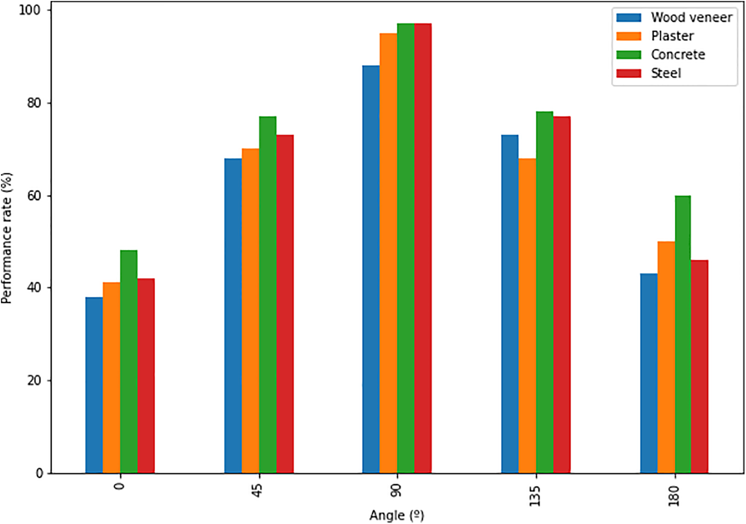
Limit point of performance rate at which the arm detaches in different materials and inclinations.
The control architecture has been tested using the four-legged physical robot and the simulation environment. In both cases, the user defines a body trajectory, such as a square or a circle. In the first case, only the configuration of four legs has been tested (video available at https://youtu.be/6PVj6xO7kCk), due to the limitation on the process of building more legs. In the second case, removing these limitations and thanks to the modularity of the robot, more configurations have been tested (video available at https://youtu.be/nOxRKEuagnw), such as five, six, seven, and ten-legged robots. Once the user has defined the body trajectory to be performed, the entire system automatically follows it, and when finished saves the results for interpretation. During the trajectory, the robot starts from a comfortable position to stand up and perform the trajectory. If during this process one or more suction cups detach from the supporting plane (estimated due to pressure sensors), the whole-system controller sends a command to stop movements and keep the current position until the user checks the failure and sends a “resume” command.
During the tests, the system is tracking reactive torques, the real position of the body, the commanded and estimated ones (estimated by a single module), as well as the commanded and real position of each motor. Figure 10 shows the reactive torques that appear in the second, third and fourth motors of a single module as a result of a commanded trajectory. The first motor is fixed at its origin, since only three motors are needed per module to control the body position whenever the robot is not required to change from one plane to another. As illustrated in that figure, the torques are lower than the stall torques, especially for the second joint, whose function is mainly to move the leg without opposition to gravity. Torques of the last three motors are irrelevant since the entire wrist is disabled when the suction cup is attached. This is done to avoid overcurrents and to reduce the impact of the hyperstaticity of the system, allowing as well the free orientation of the suction cup against the surface. At the end of the trajectory, the error between the commanded body position and the estimated one is contrasted, as well as the error between the real and estimated positions. Furthermore, a 3D representation of the trajectory is shown to the user. The mean squared error between the commanded and estimated position is

Reaction torques in the second, third, and fourth motors of a single module when a circular trajectory is commanded.
The robot payload increases with the number of modules and varies with the distribution of the modules. In the case of the developed body, the payload when it is standing, as shown in the videos, is around 2.5 kg (including the weight of the developed body). The weight that a single module can support when attached to the ceiling is around 7.74 kg.
Conclusions
This article presents a new concept of a fully modular climbing robot, in which each of its legs is a complete autonomous robotic module with seven degrees of freedom with the ability to share information and energy with other legs.
The robot can be configured with a different number of legs to adapt its characteristics to move in complex environments with vertical surfaces and even ceilings. It can carry inspection equipment such as 3D cameras, ultrasonic, or LIDAR sensors to perform robotic inspection and monitoring works in civil infrastructures such as tunnels, bridges, roads, or cooling towers. The legs use a specifically designed suction cup, equipped with its own turbine, to create the vacuum necessary to ensure the robot’s adherence.
Due to the nature of infrastructure inspection work, the robotic concept has been designed to be versatile, capable of being configured in different ways depending on the load and inspection elements to be transported. In addition, the modular concept provides the robotic system with resilience capabilities.
The fully modular concept implemented allows communication and collaboration between the different robotic legs that form the climbing robot. This collaboration not only allows to coordinate the walking or climbing actions, but is also able to contribute to the mechanical task of the whole robot and even, if necessary, to provide the necessary energy for it and share it with other robotic legs with four different operating modes. In this way, the robot implements adaptive and resilient behavior characteristics, so that the robot can adapt to the different situations that may occur during the development of its tasks, such as the mechanical failure of one of its legs or the exhaustion of the energy of one of them.
Among the different alternatives available to achieve robot adhesion, the ROMERIN robot uses an adhesion system based on vacuum generation. This system is the most versatile and reliable for civil infrastructure inspection tasks. Unlike other climbing robots, the ROMERIN robot generates the vacuum of each module or leg in each of them, so that the modules are responsible for managing their own suction cup.
The mechatronic design of the robotic modules or legs has been developed according to the modular concept, including the suction system, the controller and communication system, and the energy management system that includes four power sharing operation modes.
Following the modular concept presented, high-level control delegates the low-level management of the modules to the electronic onboard of the modules. Therefore, the control system is divided into two main parts, a set of a nondefined number of module controllers and the whole-system controller. The control architecture of the whole-system controller is therefore focused on the body position control, to imitate the animal world, where individuals care about the body movement, without thinking in a single leg control. To implement robot behavior and safety control, the whole-system controller architecture is hierarchical and it has been divided into three main levels. The definition and responsibilities of each level have been presented in this article.
Finally, several experiments have been carried out using a four-legged robot configuration to test the modularity concept, the mechanical design, and the electronics. The gripping system has been tested on different situations and surfaces of different materials, analyzing the power consumption and the effects on robot autonomy. The performance of the control architecture has been tested with different body trajectories.
Footnotes
Declaration of conflicting interests
The author(s) declared no potential conflicts of interest with respect to the research, authorship, and/or publication of this article.
Funding
The author(s) disclosed receipt of the following financial support for the research, authorship, and/or publication of this article: The research leading to these results has received funding from RoboCity2030-DIH-CM, Madrid Robotics Digital Innovation Hub, S2018/NMT-4331, funded by “Programas de Actividades I+D en la Comunidad de Madrid” and cofinanced by Structural Funds of the EU. The project on which this research is being developed was initially funded by the Spanish National Plan for Scientific and Technical Research and Innovation, DPI2017-85738-R.