
Abstract
To improve the human–computer interaction ability and environmental adaptability of the quadruped robot, especially the ability of the quadruped robot to follow people and avoid obstacles. In this article, the fusion of ultra-wideband positioning technology and three-dimensional laser radar is applied to a quadruped robot. The core is to scan the surrounding obstacle information through three-dimensional laser radar, locate the position of both the quadruped robot and the target person, complete the obstacle avoidance, and follow the task of the quadruped robot through an efficient path planning algorithm. To meet the high-precision positioning requirements, the ultra-wideband positioning system is used in this article. When calculating the coordinates, we propose a three-sided weighted least squares positioning algorithm. To improve the efficiency and stability of the quadruped robot in path search, based on the A* algorithm, this article improves and proposes an incremental A* algorithm based on a sliding window. The feasibility and effectiveness of our method are verified by computer simulation analysis and real experiments of the quadruped robot.
Introduction
More than half of the earths land surface is rugged and unstructured environments. Tetrapod mammals can move efficiently in similar environments and have strong adaptability and flexibility to dynamic unstructured environments. Therefore, a series of quadruped robots with quadruped motion characteristics, such as Bigdog, 1 Hyq, 2,3 and Mini cheetah, 4,5 emerge with them as bionic objects. Although the wheeled robot has the characteristics of simple structure, small motion fluctuation, and low energy consumption, it is limited to the flat indoor environment. Compared with wheeled robots, quadruped robots can not only adapt to the indoor environment but also walk freely in rugged, irregular, and unstructured bumpy environments, showing their strong environmental adaptability and mobility. In the study of such robots, robots should be able to interact with people, realize natural interaction, and adapt to complex environments. Therefore, the study of environmental adaptability and the human–computer interaction ability of quadruped robots has become the focus. Among them, solving the obstacle avoidance and personnel tracking of quadruped robots in complex environments becomes a key research field.
The perception ability of the quadruped robot in the interaction process of surrounding environments depends on the hardware sensors mounted on it. Boston Dynamics has been exploring the environmental perception of quadruped robots very early. They use a planar laser scanner and binocular camera as tools for Bigdog 6 quadruped robot to perceive the surrounding environment and realize the autonomous obstacle avoidance of quadruped robot. The LS3 quadruped robot is equipped with a laser scanner, a two-degree-of-freedom pan–tilt, a binocular camera, and other perception tools to realize the autonomous movement of the quadruped robot in a complex environment. 7 In addition, the Littledog quadruped robot obtains environmental information through the stereo vision principle of a binocular camera and realizes walking in the rugged environment including irregular large obstacles. 8 In 2020, MIT Cheetah2 used the Hokuyo UTM-30LX-EW laser range finder to sense the information of its surrounding environment to realize the jumping of obstacles. Through the detected ground plane and the front of the obstacle, the distance and height of the obstacle can be inferred. 9 In recent years, with the gradual maturity of vision sensors and SLAM technology, some scholars have also launched research on this. In 2018, Nemoto et al. 10 presented an approach to the simultaneous localization and mapping (SLAM) for the quadruped robot in crawling locomotion to achieve its autonomous operation in an unknown environment. They applied the SLAM algorithm based on the unscented Kalman filter and realized accurate estimates of the robot trajectory and the locations of surrounding landmarks simultaneously. In 2020, Pudchuen et al. 11 proposed vision-based control to enhance navigation of the quadruped robot to deal with rough or uneven terrain rather than employing force sensors. By using visual odometry, the robot can localize its position and orientation accurately.
In terms of personnel identification and tracking, the more commonly used method is to identify the human body such as legs, 12,13 face, 14 trunk, 15 and other specific parts of the tracking. There are also scholars who realize feature extraction through the image recognition method. 16 Although there are few studies in this aspect of quadruped robots, some scholars have made some achievements. Perdoch et al. 17 proposed a tag tracking system, which uses a near-infrared camera, reflective tag, and laser radar to allow specific users to specify themselves as the leader of the robot and guide the robot to move along the required path. In the study by Zhang et al., 18,19 reflective markers are used to distinguish the leader of the quadruped robot, and Zhang et al. 19 use the A* algorithm of virtual extended obstacle grid for path planning to achieve obstacle avoidance tracking. Pang et al. proposed a visual approach under a novel T-D-R framework to solve the long-term following problem of quadruped robots. The proposed T-D-R framework is composed of a visual tracker based on a correlation filter, a person detector with deep learning, and a person re-identification module. The result of the tracker is verified by the detector to improve tracking performance. 20 And there are also some scholars who used YOLOv3 neural network based on stereo vision for target personnel detection and tracking, like Jiang et al. 21
In the above methods, the use of a plane laser scanner in environmental perception can only obtain the obstacle information at a horizontal plane, and it cannot be detected for lower obstacles. To obtain the three-dimensional (3D) information, other auxiliary tools are needed. The binocular camera is too dependent on accurate parameter calibration, and its horizontal field of view is limited. In personnel tracking, although human tracking can be carried out through human-specific recognition and neural network target detection, quadruped robots may lose previous tracking personnel in the case of large numbers of people around them. Although the tracking target can be specified by posting specific reflective markers on the tracking target in the studies of Perdoch et al. 17 and Zhang et al., 18,19 the posting marker materials are easily affected by the light environment and then be lost. In the case of multi-target tracking, turns to appear large fluctuations and poor tracking effects.
To get the precise position of the quadruped robot and the navigator, it is worthwhile to need a high-precision positioning technology. At present, in terms of wireless positioning technology, many traditional mainstream positioning technologies expose many inevitable drawbacks. Wireless Fidelity (Wi-Fi) positioning technology is convenient to use existing wireless devices to achieve positioning function. However, the security of Wi-Fi is poor, the power consumption is high, the positioning accuracy is at the meter level, and the spectrum resources are nearly saturated. Radio frequency identification technology mainly identifies whether the person exists in a certain area, which cannot realize real-time tracking, and the positioning application lacks a standard network system. The cost of network construction and establishment is difficult. The biggest advantage of Zigbee positioning is low power consumption, but the penetration of Zigbee is weak, and the anti-interference ability is insufficient. The positioning accuracy cannot reach the centimeter level, which is not suitable for a complex environment. Outdoor positioning technology Global Positioning System (GPS) positioning system can only work in the visible range of GPS positioning satellites, civil GPS positioning accuracy can only be in meters, cannot meet the high-precision positioning. Ultra-wideband (UWB) positioning technology uses nanosecond to microsecond non-sinusoidal narrow pulse to transmit data. Compared with other positioning technologies, UWB positioning has many advantages such as high positioning accuracy, good security, high transmission rate, large system capacity, low power consumption, and strong anti-interference ability. Its positioning accuracy can reach 10 cm, which is the positioning technology with the highest positioning accuracy in indoor positioning and can fully realize high-precision positioning.
Based on the above problems, this article proposes a novel obstacle avoidance and tracking strategy for the quadruped robot. The UWB positioning system and 3D laser radar are combined to apply to quadruped robots. The communication between UWB tags and base stations is a good way to make up for the current vision is difficult to distinguish between multi-target tracking personnel. The improved trilateral weighted least squares positioning algorithm is used to improve the positioning accuracy. In addition, the use of 3D laser radar allows quadruped robots to detect obstacles of different sizes as much as possible and improves robustness. The obstacle information after point cloud processing is combined with the positioning information to construct the 2D grid map. An incremental A* path planning algorithm based on sliding window is introduced, and finally, the obstacle avoidance and tracking of quadruped robots are realized. The method used in this article not only realizes the tracking of multi-target personnel but also can obtain good application innovation in quadruped robots. The innovations of this article are as follows: The fusion of 3D laser radar and UWB is applied to the field of the quadruped robot, which fully realizes the tracking function of a specific target in the multi-target of a quadruped robot. Based on the traditional trilateral localization algorithm, the trilateral weighted least squares localization algorithm is proposed for improving the location accuracy. To improve the efficiency and stability of the path search, an incremental A* algorithm based on a sliding window was used based on the patent of our laboratory. A quadruped robot platform is built independently, which has high dynamics and terrain adaptability, and can achieve stable movement of multiple gaits. It can provide better technical support for the physical platform verification in this article.
This article is organized as follows. In the second section, we describe the components of the hardware of environmental perception. In the third section, we analyze the improved UWB positioning method. The laser radar point cloud processing method is shown in the fourth section. In the fifth section, we illustrate the path planning algorithm. The sixth section is verified by simulation and experiment based on the quadruped robot. The last section is the summary and future outlook.
Hardware platform
The hardware facilities used in this experiment are mainly composed of the following three parts in Figure 1: robot platform, environment perception module, and processing module.

Overall diagram of hardware and software of the robot.
Robot platform
The author’s intelligent human–computer interaction innovation team developed a quadruped bionic robot with length, width, and height of 62 cm, 26 cm, and 37 cm, respectively, and 15 kg of weight after carrying sensors, as shown in Figure 2. Each leg of the robot is composed of three 48Nm brushless DC motors, which are divided into the lateral hip joint with 180 degrees of rotation, forward hip joint with 180 degrees of rotation, and leg joint with 150 degrees of rotation. The leg is made of an aluminum alloy connecting rod. The robot lower machine controller uses UpBoard for offline motion calculation, uses CAN bus to communicate with the motor, controls the robot motion, and uses RadioLink AT9S Pro to control the handle to control the robot motion. At the same time, the motion module of the robot is powered by a lithium battery with an output voltage of 48 V, and the laser radar module is powered by a 12-V power supply converted by a power conversion module, which can last for 1.5 h when all modules work.

Physical platform of the quadruped robot.
In addition, the robot carries the current more advanced types of sensors. A 16-wire laser radar RS-LIDAR-16 (RoboSense Technology Co. LTD, China) is installed on the back to detect obstacles of different sizes when the robot walks. In terms of positioning sensors, the LinkTrack UWB (Shenzhen Nooploop Technology Co. LTD) positioning system is installed on the back of the robot, which can achieve stable tracking of specific targets in multiple targets. The inertial measurement unit (IMU) sensor is responsible for estimating the entire motion state and motion data of the quadruped robot, including attitude angle, linear velocity, foot position, and other parameters. The model predictive control (MPC) 22 model uses these data to calculate the optimal plantar force, so as to derive the joint torque and realize the smooth and rapid movement of quadruped robots, which can provide better technical support for the verification of the physical platform in this article. Figure 3 is the sensor and function configuration diagram of the quadruped robot.

Sensor configuration and function description.
Table 1 shows the motion performance parameters of the quadruped robot. The body structure of the quadruped robot adopts the structure of a quasi-direct drive planetary reducer, which can withstand the maximum weight of 15.07 kg. The robot has high dynamic motion ability, which can realize the switching between walk, trot, flying trot, pronk, bound, and other gaits. The running speed of the flying trot gait can reach 3.24 m/s. At the same time, the robot has a certain climbing ability, and the maximum climbing angle can reach 35°.
Quadruped robot motion parameters.

Environment perception module
The 3D laser radar used in this article is shown in Figure 4. The laser radar adopts the hybrid solid-state laser radar mode, which integrates 16 laser transceiver components. The measurement distance is as high as 150 m, and the measurement accuracy is within 4 cm. The number of outlet points per second is as high as 300,000 points. The horizontal angle measurement is 360°, and the vertical angle measurement is 30°. In the actual test, we only consider the quadruped robot to avoid the obstacles in front and track the target personnel in front. Therefore, we ignore the obstacle information behind the quadruped robot. We set the horizontal field of view angle to 180°, which can fully achieve the desired goal.
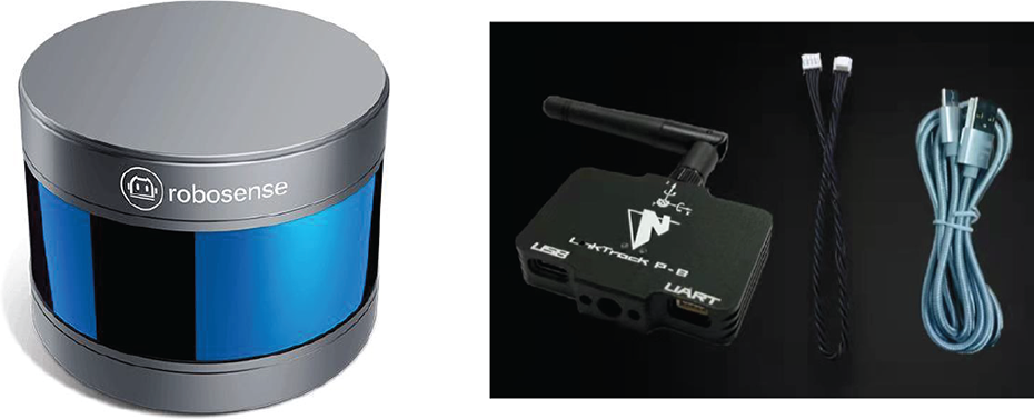
3D laser radar and UWB used in the quadruped robot. UWB: ultra-wideband.
This experiment uses LinkTrack UWB hardware module, as shown in Figure 4, which is a multifunctional system based on UWB technology, local positioning function, supporting the configuration of tags, base stations, and other roles. Local positioning is a real-time positioning mode that supports the integration of positioning, navigation, timing, and communication. It is divided into three roles: tag, base station, and console. The tags are measured in real time and the coordinates are calculated. The base station and the console output the location information of all tags in real time.
Processing module
We use NVIDIA Jetson AGX Xavier (Santa Clara, California) as the controller of sensor data processing, mapping, and other tasks of the quadruped robot. The data of laser radar are transmitted to the controller through the wireless network. The UWB monitoring module and the controller are connected by universal serial bus, and the data sharing is completed under robot operating system.
UWB positioning algorithm
UWB ranging method based on double-sided time-of-flight two-way ranging
This article adopts the double-sided time-of-flight two-way ranging method. This method does not require time synchronization between the two sides of the communication. At the same time, the two groups of time differences on the respective time stamps ends of the communication are recorded, which greatly improves the ranging accuracy. As shown in Figure 5, the communication ranging between base station A and label B is supposed to be achieved, the specific ranging process is as follows. Firstly, base station A opens the TX serial channel on its time stamp to apply for sending the signal and records the time stamp

Double-sided time-of-flight two-way ranging method.
Thus, we can get four groups of time difference between base station A and label B


Therefore, the flight time of wireless signal for base station A and label B communication is

So, the communication distance between the two can be obtained as

where C is the speed of light.
Improved trilateral weighted least squares localization algorithm
As shown in Figure 6, the traditional trilateral positioning algorithm is based on the position coordinates of the three base stations B 1, B 2, B 3, and the distance between the tag and the three base stations d 1, d 2, d 3 to obtain the position coordinates of the tag T. However, in practical applications, due to irresistible interference factors such as the external environment, the consistency of measurement distance accuracy from each label to the base station cannot be guaranteed. This difference in ranging accuracy inevitably affects the final positioning. Therefore, to further improve the positioning accuracy and reliability, an improved trilateral positioning algorithm is proposed based on the original trilateral positioning algorithm.

Trilateral positioning principle diagram.
Assuming that all base station coordinates we establish are
Therefore, the following equation can be obtained as

The above equations are solved by the least square method. The first equation of the equations is subtracted from the last equation in turn and sorted into matrix form

It can be simplified as follows

Specially, when


According to the principle of least square method, the least square estimation of X can be obtained as

Considering the external interference factors in practical application, the weighted compensation factor matrix W and formula (9) are introduced for the following transformation

W is a weighted matrix designed according to the distance error from the tag to each base station, which is usually a symmetric positive definite matrix. Then, we obtain the least square solution after label coordinates weighting

Laser radar point cloud processing
Point cloud filtering
In this article, the statistical filtering algorithm is used to remove the large-scale noise of the 3D point cloud, so that the density of irregular point cloud data becomes smooth, and the outliers and unnecessary noise data can be removed.
The main idea of the statistical filtering algorithm is to assume that the average distance between each query point and its neighborhood point in the 3D point cloud satisfies the Gaussian distribution. A distance threshold is determined by its mean and variance, and points outside the range of the distance threshold are judged as outliers and removed.
Firstly, it is assumed that there are m neighborhood points in the neighborhood of point r in the 3D point cloud, and the distance from r to each neighborhood point is dj
. Therefore, the average distance

Then, the average distance of m neighbor points of all points is statistically analyzed, and the mean μ and standard deviation σ are calculated. The distance threshold

Among them, α is the threshold coefficient. Finally, by judging whether the average distance
Ground point removal
Environmental perception is usually only interested in obstacles on the road. The ground may be mistaken for obstacles, and the obstacles below the height of quadruped robot cannot be ignored. Therefore, it is necessary to separate the ground point cloud and non-ground point cloud. In this article, the random sample consensus (RANSAC) algorithm 23 is used to find out the plane representing the ground. The ground point cloud segmentation map is shown in Figure 7. The following is the core idea of the algorithm. The distribution of the whole point cloud data can be described by a mathematical model. Three points are randomly selected from the original point cloud data set, and a plane model is determined according to these three points. Using this mathematical model to estimate other points, the points that adapt to the model are called local points, and the points that cannot adapt to the model are external points. Repeated iterations, select the model with the largest number of local points as the optimal plane model.

The ground point cloud segmentation map.
In general, the normal plane equation of the spatial plane is

In the above formula,
Three points

The model is used to determine whether other points in the point cloud data set are local points, and the distance from the point to the plane is set as the judgment criterion, as shown in the following equation

It is necessary to set the appropriate distance threshold θ according to the actual point cloud data to approximate the fitting plane. The point within the threshold θ corresponds to the model, which is the local point. The point that exceeds the distance threshold θ are outliers. The number of local points under the model is counted.
The above process requires multiple iterations. The group of points with the largest number of local points is selected, and the maximum number of local points is fitted to obtain the final plane model. Therefore, it is necessary to determine the appropriate number of iterations k.
p denotes the probability of random sampling to local points, and c denotes confidence. This parameter represents the expected probability of RANSAC algorithm providing useful results after running. n represents the number of data that need to be selected to calculate model parameters. k represents the number of iterations. pn
denotes the probability of randomly selected n points being local points.

For the logarithm of the upper formula, the value of the inverse k is

k is the required iteration termination condition. Exit the loop when the actual number of iterations is greater than k.
Map modeling
This part is to map the UWB coordinates of the quadruped robot, the UWB coordinates of the target, and the obstacle coordinates detected by laser lidar.
UWB base stations are stationary, so the resulting coordinates are equivalent to global coordinates, but because the radar is mounted on the quadruped robot, the radar will move with the robot. For a fixed obstacle, the coordinates of the obstacle in the global coordinate system do not change when the quadruped robot moves, but the coordinates read by the radar are real-time changing. Therefore, it is necessary to transform the coordinates in the radar coordinate system into the global coordinate system. We do not consider the height of the object in 3D space and assume that the height of the obstacle is within the height range that the laser radar can detect, the 3D point cloud of the laser radar is projected to the 2D plane. Assuming the global coordinate system {Q} and radar coordinate system {V}, we set the origin of the map coordinate system on the laser lidar, so that we can only do the rotation transformation without the translation transformation to reduce the error. So the rotation matrix around z-axis is

Thus, coordinate transformation can be realized by the following equation

After obtaining the obstacle coordinates converted to the global coordinate system, they are mapped to the map together with the relative coordinates of the quadruped robot and the target.
Raster is used to divide the robot workspace with the same size of the grid, and the grid array is used to represent the environment. Obstacles exist in the environment represented by grids and occupy a certain number of grids, as shown in Figures 8 and 9. Assuming that black grids are used to represent obstacle space and white grids are used to represent free space, the location of black grids in white grids is the location of obstacles in the environment of the quadruped robot.
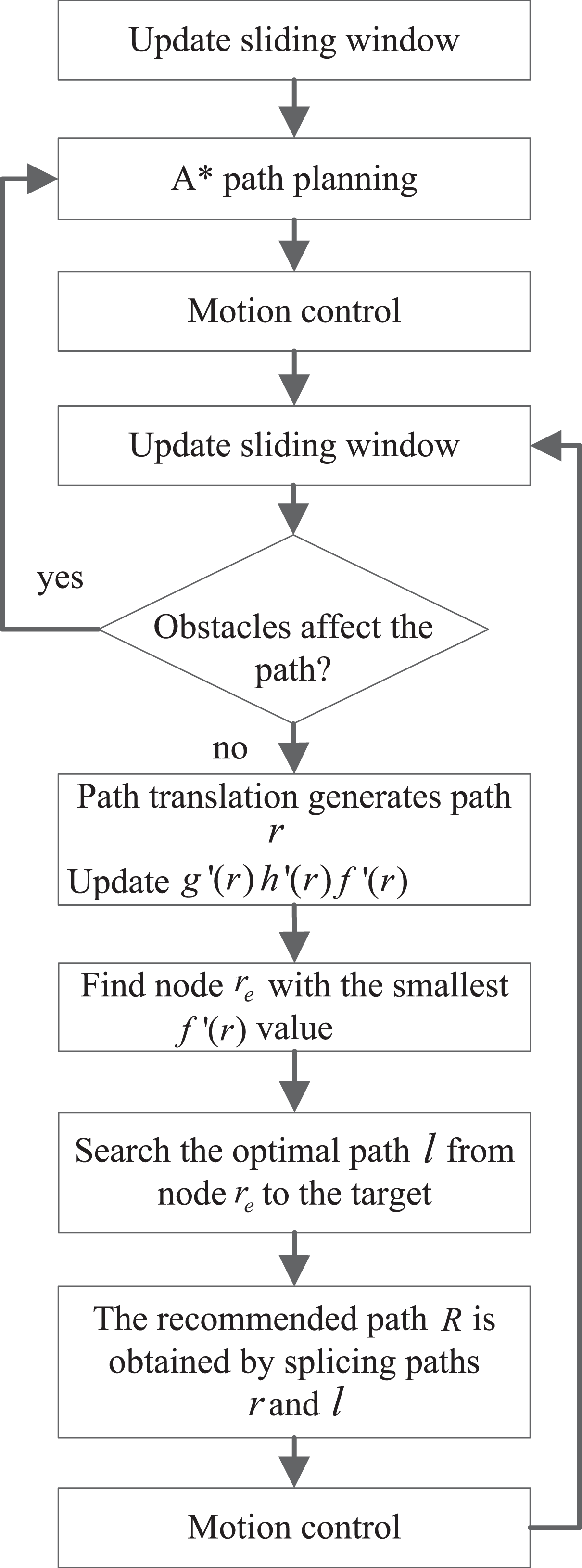
Flow chart of incremental A* algorithm based on sliding window.

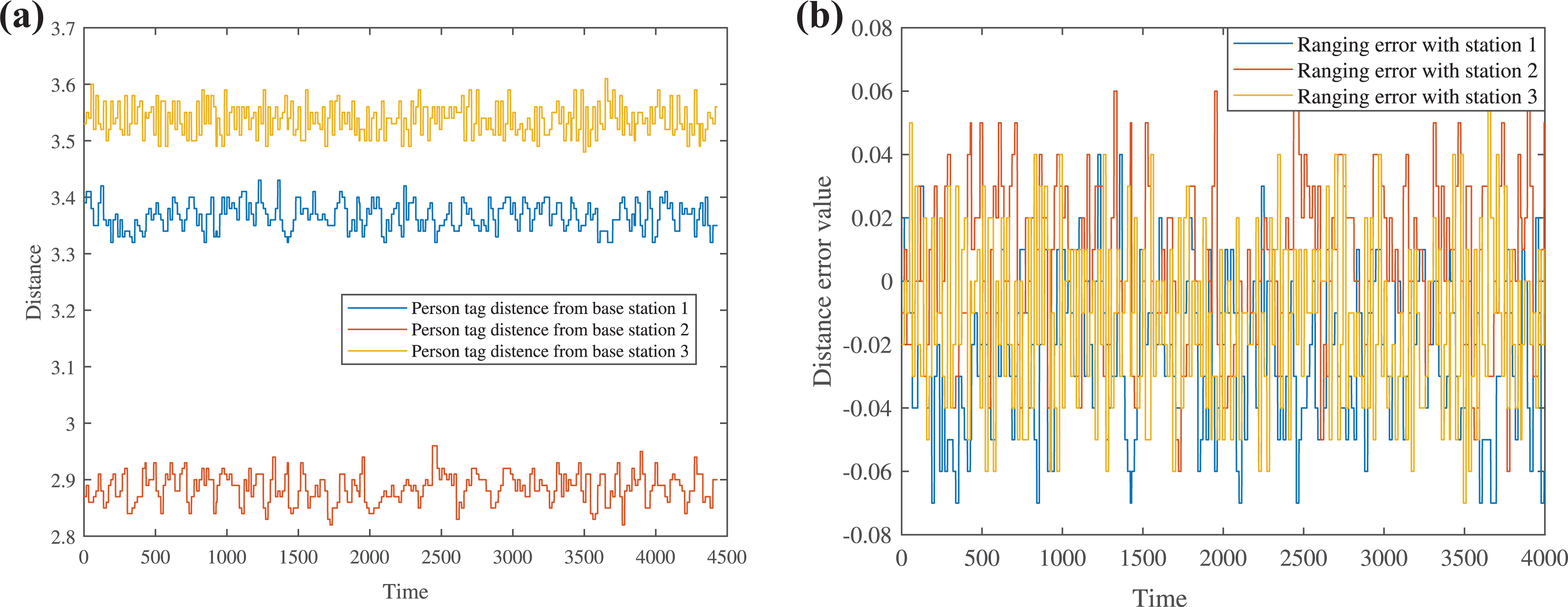
(a) Distance variation and (b) error of robot tag.
In our work, to describe the surrounding environment information more accurately, the accuracy represented by each grid size is 0.1 m. Considering the operation speed of the processor in practical application and the efficiency of the path planning algorithm to traverse the grid, the size of the grid map we convert is 200 × 200, which is the result of our comprehensive test.
Incremental A* path planning algorithm based on sliding window
For the quadruped robot, its position is equivalent to the starting point of the path planning, and the position of the pilot is equivalent to the target point of the path planning. Since the quadruped robot is walking with the pilot, the detected environmental information will be updated in real time with the change of the position of the quadruped robot, which makes the starting point and the target point of the path planning become no longer fixed geographical coordinates. However, the traditional A* path-finding algorithm is a static path planning algorithm. After the path planning, new moving obstacles are encountered, resulting in slow robot response and unable to adjust the route in time. Moreover, the A* algorithm has to start from the starting point and replan when the environment changes, which will greatly reduce the path search efficiency. For those reasons, the incremental A* path planning algorithm based on the sliding window in this article greatly improves the path planning efficiency. 24
The environmental information scanned by 3D laser radar and UWB positioning information are mapped into a 2D grid map. The position of the quadruped robot and the position of the pilot are set as the starting point and the target point of the path planning, respectively. To increase the safe distance between the quadruped robot and the actual obstacle, the expansion of the obstacle is carried out. The sliding window needs to be large enough to avoid the situation that the starting point or the end point exceeds the scope of the sliding window. The sliding window is constructed in the grid map. The 2D coordinate plane is established with the current position of the quadruped robot as the origin. The area of the sliding window occupies four quadrants of the 2D plane coordinate. Therefore, when the target point moves in the sliding window, the current position of the quadruped robot is taken as the starting point, and the current position of the movable target point is taken as the end point. The optimal path is calculated and obtained using the incremental A* algorithm. The flowchart of the incremental A* algorithm based on the sliding window is shown in Figure 8.
At first, the quadruped robot searches the path according to the A* algorithm to get the optimal path with the target point. Its cost function is in equation (25)

In the formula,

The incremental A* path planning algorithm based on the sliding window avoids the replanning problem after the environmental information is updated and improves the search efficiency and the stability of the robot motion.
Simulation and experiment
In this section, we first analyze the ranging accuracy and positioning accuracy of UWB obtained by our UWB positioning method. Then, in the indoor environment, we visualize the grid map by Qt simulation tool and analyze the effectiveness of the path planning algorithm we use and the advantage of path search efficiency. Finally, to further determine the practical application of our strategy, we conduct a real experiment in an outdoor environment of 50 × 50 m2, and the results show that our quadruped robot has a good performance.
UWB ranging and positioning algorithm experiment
The positioning model of UWB deployment is as follows: Six UWB modules are used to jointly complete the positioning task, and three base station modules are used to build the UWB site model. The two tag modules represent the current position of the quadruped robot and the target position, respectively. There is also a monitor module to receive UWB transmission data.
To test the ranging accuracy of the UWB system and the positioning accuracy of the improved positioning algorithm, we set up three fixed base stations 1, 2, 3 and manually calibrate their standard coordinates in the world coordinate system as (0, −2.4), (0, 1.6), (6, 0). Then, we fixed the positions of the two labels, and their standard coordinates were (0, 2.4) and (0, 0.8), respectively. The actual distance between the two tags and the three base stations is measured manually, where the actual distance between the tags carried by the robot and the three base stations are (2.53, 1.79, 5.20). The actual distances of the tag carried by the target personnel from the three base stations are (3.39, 2.88, 3.55).
Figure 9(a) shows the variation of the distance between the robot tag and the three base stations over a certain period time. Figure 9(b) shows the distance error of the robot tag. Figure 10(a) shows the variation of the distance between the person tag and three base stations in a certain period time. Figure 10(b) shows the distance error of the person tag. It can be seen from Figures 9 and 10 that the distance change from the label to the base station can be maintained at a certain level stably. The fluctuation of UWB ranging accuracy is not large, and the ranging error can always be maintained at about 0.1 m, which is a very good result for the current UWB system.
(a) Distance variation and (b) error of person tag.
According to the ranging results, the improved trilateral weighted least squares positioning algorithm is introduced, and the position coordinates of quadruped robot and human can be obtained by coordinate calculation. Figure 11(a) shows the coordinate change of person tag, and Figure 11(b) is the corresponding coordinate error. Figure 12(a) shows the coordinate change of the robot tag. Figure 12(b) is the coordinate error of the robot tag.

(a) Coordinate variation and (b) error of person tag.

(a) Coordinate variation and (b) error of robot tag.
It can be seen from Figures 11 and 12 that the positioning coordinate value can always be maintained in a certain range, and the error in this range can be maintained at about 0.1 m. It can be seen that the coordinates calculated by our algorithm have little loss, and the positioning accuracy is also effective for the real application of the quadruped robot.
Incremental A* path planning algorithm experiment
To test the effectiveness of the path planning algorithm for obstacle avoidance tracking, we build a 5 × 5 m2 UWB site model in the room and place an obstacle, as shown in Figure 13.
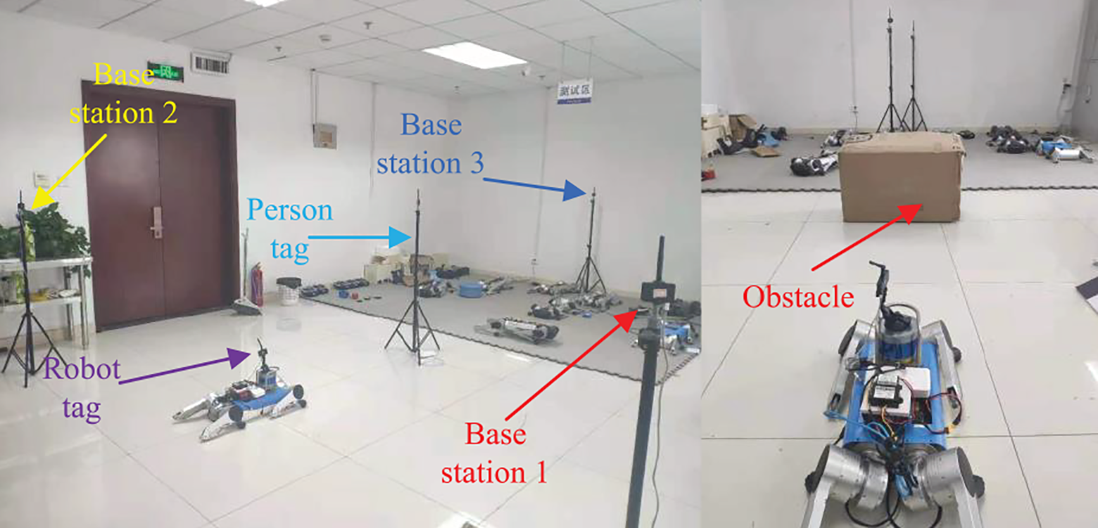
UWB site building model and obstacles.
After locating the position information of the tracked target by UWB positioning system and the current position information of the quadruped robot itself, the environmental information scanned by laser radar is transformed into the form of a grid graph, and the incremental A* path planning algorithm is further introduced to complete the obstacle avoidance tracking of the target person. Figures 14 and 15 show the path planning of static obstacles and dynamic obstacles, respectively.

Simulation experiment of path planning under static obstacles.

Simulation experiment of path planning under dynamic obstacles.
In Figures 14 and 15, yellow is the feasible shortest path planned, and black represents the obstacle. The picture of the robot in the figure is the position of the robot. The red five-pointed star represents the target location. To further ensure the safety of obstacle avoidance of quadruped robots, we carried out a certain expansion around the obstacle. The black obstacle information in the figure has been expanded to a certain extent. It can be seen from Figure 14 that in the case of static obstacles, our algorithm can plan the path according to the different positions of the quadruped robot. The quadruped robot will update the real-time path according to the current position. It can be seen in Figure 15 that in the case of dynamic obstacles, our algorithm will conduct real-time path planning according to the change of the position of the obstacles. After the obstacle moves, the quadruped robot will generate new recommended paths according to the remaining paths. The oblique part of the yellow path in the graph is the result that the algorithm preferentially selects the oblique path, which further improves the efficiency of the quadruped robot when reaching the end point.
Since the incremental A* algorithm only performs incremental path search, it is more efficient than the A* algorithm in path replanning. Table 2 compares the total number of grids traversed by multiple planning. From this table, it can be seen that the number of grids traversed by the A* algorithm is more than five times that of the incremental A* algorithm.
Comparison of the total number of cells searched by the A* algorithm and the incremental A* algorithm.

Personnel following and obstacle avoidance tests in the real world
We chose a 50 × 50 m2 outdoor site for obstacle avoidance tracking experiment. The site is set up as shown in Figure 16.

Base station construction and target personnel diagram.
To eliminate the interference of the external environment caused by the construction of the base station as much as possible, the height of the three base stations is maintained at the same level. Considering that the height of the label carried by the machine dog is about 0.6 m when standing, the height of each base station is maintained at about 1.2 m, and the height of the tracked handheld label is about 1.3 m, we carried out obstacle-free tracking experiment and obstacle avoidance tracking experiment.
First, we did a tracking test without obstacles. On an outdoor site of 50 × 50 m2, we built a three-base station UWB system and conducted an obstacle-free tracking experiment for target personnel. Figure 17 shows the process of obstacle-free tracking of the target person by the quadruped robot. The red dashed line with an arrow represents the trajectory and direction of the quadruped robot, and the green dashed line with an arrow represents the trajectory and direction of the target person. The overall trajectory of the quadruped robot is P 0–P 1–P 2–P 3–P 4–P 5, and the overall trajectory of the target person is A 0–A 1–A 2–A 3–A 4. The specific process is as follows: At the beginning, the quadruped robot is at point P 0, and the target person is at point A 0. The quadruped robot first moves from P 0 to P 1 close to the target personnel, and then the target personnel moves from A 0 to A 1, and the quadruped robot adjusts the direction from P 1 to P 2. The target personnel continues to move from A 1 to A 2, and the quadruped robot moves from P 2 to P 3. After that, the target personnel change the direction of motion and move along the A 2–A 3–A 4 trajectory. The quadruped robot also adjusts its direction to track the target personnel along the P 3–P 4–P 5 trajectory. Then, we conducted obstacle avoidance tracking experiments with obstacles. We tested on the same site. Figure 18 shows the process of the quadruped robot avoiding obstacles twice and tracking the target person. The overall trajectory of the quadruped robot is R 0–R 1–R 2–R 3–R 4–R 5–R 6–R 7, and the overall trajectory of the target personnel is E 0–E 1–E 2–E 3–E 4. The motion process is as follows. At first, the quadruped robot is at point R 0, and the target person is at point E 0. Another experimental person is regarded as an obstacle and a nontarget interference person. The target person first remains immobile, and the quadruped robot attempts to avoid the obstacle along the trajectory of R 0–R 1–R 2. In the process of the quadruped robot moving from R 2 to R 3 to complete obstacle avoidance, the target person moves from E 0–E 1–E 2, and then the quadruped robot continues to track the target person from R 3 to R 4. Another experimental person continues to act as the obstacle to the quadruped robot. The quadruped robot avoids the obstacle again along the trajectory of R 4–R 5–R 6. In this process, the target person moves from E 2–E 3–E 4, and finally, the quadruped robot moves from R 6 to R 7 to track the target person after bypassing the obstacle. In the process of obstacle avoidance and tracking, the robot will plan the optimal tracking path in real time, and it will also effectively avoid dynamic obstacles. Our quadruped robot finally stably completes obstacle avoidance and tracks the walking of the target person.

Obstacle-free tracking experiment of the quadruped robot.
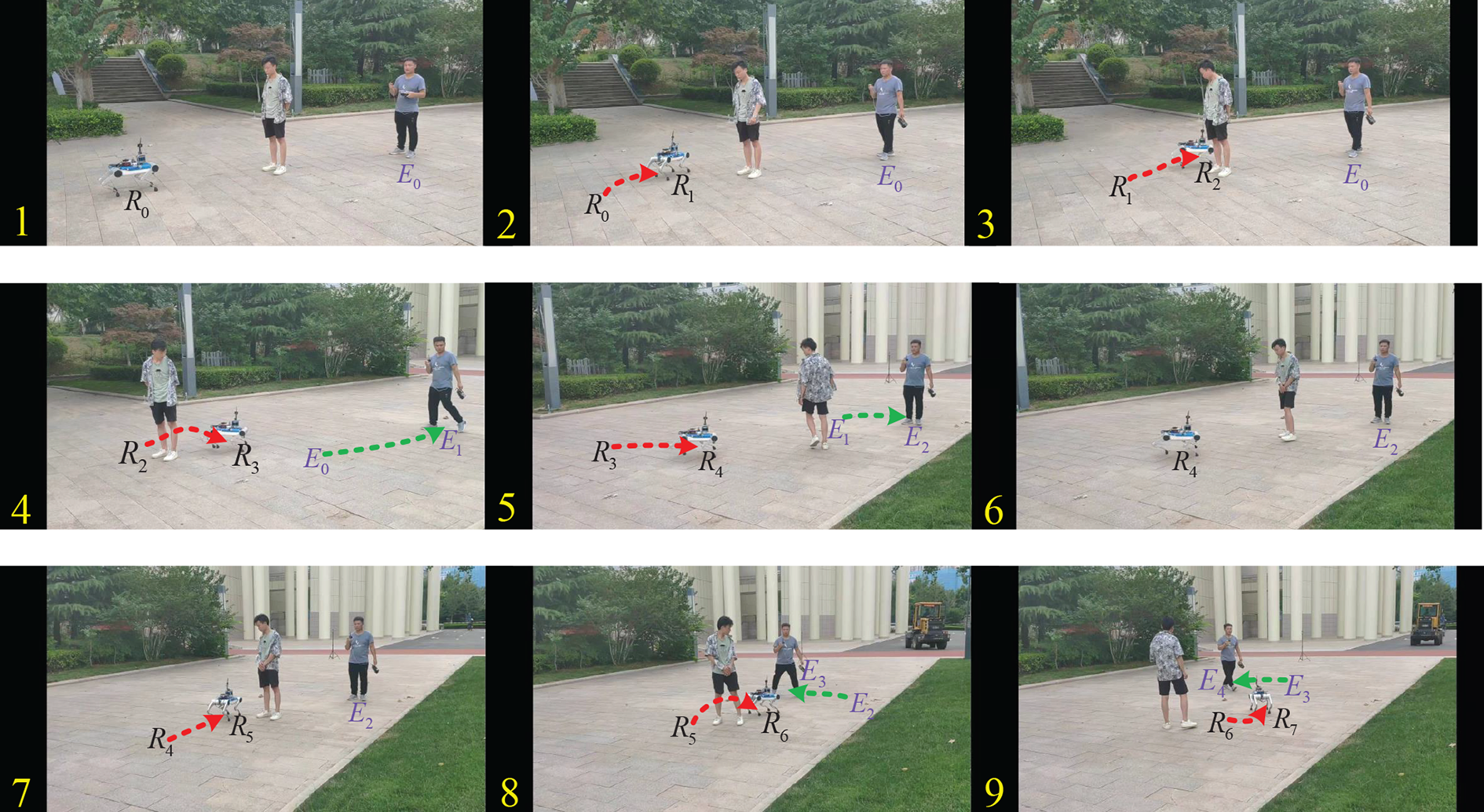
Obstacle avoidance tracking experiment of the quadruped robot.
Conclusions
This article presents a strategy of obstacle avoidance and human following for quadruped robot based on 3D laser radar and UWB positioning system. Our UWB system adopts the method of three base stations, two tags, and one monitoring. According to the original distance information between the tag and the base station, the positioning algorithm is introduced to calculate the coordinates, so as to determine the current position of the quadruped robot and the position of the tracked person. The original point cloud is obtained by laser radar scanning obstacles. After a certain point cloud processing, the simplified obstacle coordinate information is obtained. The 2D gridding of obstacle coordinate information is more conducive to integrating into the path planning algorithm. The position information obtained by UWB is also mapped to the 2D grid map through coordinate transformation. Finally, the incremental A* algorithm based on a sliding window is used to realize obstacle avoidance and human tracking of the quadruped robot.
Although UWB has been greatly improved in positioning accuracy, it will fluctuate due to external interference in communication. For example, the influence of occlusion will attenuate the signal strength caused by positioning error and different sizes. Material occlusion on the influence of communication signals is different. In the actual test, the quadruped robot will occasionally appear with small fluctuations in the movement process. Therefore, in future work, we consider the further fusion of other sensors on this basis to form a quadruped robot multi-sensor fusion obstacle avoidance and tracking system. In the aspect of path planning, the next work will consider the fusion of global path planning algorithm and local path planning algorithm to further improve the stability of path planning algorithm.
Footnotes
Declaration of conflicting interests
The author(s) declared no potential conflicts of interest with respect to the research, authorship, and/or publication of this article.
Funding
The author(s) disclosed receipt of the following financial support for the research, authorship, and/or publication of this article: This work was supported in part by the National Natural Science Foundation of China under Grant 61973185, in part by the Development Plan of Young Innovation Team in Colleges and Universities of Shandong Province under Grant 2019KJN011, in part by the Natural Science Foundation of Shandong Province under Grant ZR2020MF097, and the Colleges and Universities 20 Terms Foundation of Jinan City (2021GXRC100).