
Abstract
The accuracy of agricultural unmanned ground vehicles’ localization directly affects the accuracy of their navigation. However, due to the changeable environment and fewer features in the agricultural scene, it is challenging for these unmanned ground vehicles to localize precisely in global positioning system-denied areas with a single sensor. In this article, we present an efficient and adaptive sensor-fusion odometry framework based on simultaneous localization and mapping to handle the localization problems of agricultural unmanned ground vehicles without the assistance of a global positioning system. The framework leverages three kinds of sub-odometry (lidar odometry, visual odometry and inertial odometry) and automatically combines them depending on the environment to provide accurate pose estimation in real time. The combination of sub-odometry is implemented by trading off the robustness and the accuracy of pose estimation. The efficiency and adaptability are mainly reflected in the novel surfel-based iterative closest point method for lidar odometry we propose, which utilizes the changeable surfel radius range and the adaptive iterative closest point initialization to improve the accuracy of pose estimation in different environments. We test our system in various agricultural unmanned ground vehicles’ working zones and some other open data sets, and the results prove that the proposed method shows better performance mainly in accuracy, efficiency and robustness, compared with the state-of-art methods.
Introduction
Nowadays, artificial intelligence (AI) makes agriculture more and more simple and efficient, and many unmanned ground vehicles (UGVs) used in agricultural production help reduce farmers’ labor work and promote the farming procedure. 1 Localization is one of the most crucial modules for the navigation of agricultural UGVs in many precision agriculture scenarios, such as cultivating, sowing, fertilizing and watering. A global positioning system (GPS) is widely used in UGVs’ localization to help them obtain accurately (up to centimeters) longitude, latitude, and altitude. However, in some open areas where a signal is blocked by buildings and some indoor scenes that cannot be covered by GPS satellites, it is hard for UGVs to get their poses by simply relying on GPS. 2 Although some indoor localization methods, such as ultra-wideband (UWB) 3 and quick response code positioning, 4 can be used to replace GPS in industrial scenarios, which need special equipment to be settled down at a known position in advance, they are not suitable for agriculture due to the lack of flexibility. To this end, an efficient, adaptive and flexible localization method makes a lot of sense for these UGVs in GPS-denied areas. Lidar, camera and inertial measurement unit (IMU) are common and widely used sensors equipped in UGVs to assist localization, and simultaneous localization and mapping (SLAM) is a software algorithm that processes and integrates the data coming from these sensors to get a sensible pose.
For quite a long time, SLAM has been considered to be a reliable approach to help mobile robots localize and percept in unknown environments by researchers. 5 Visual-based SLAM methods and Lidar-based SLAM methods are two main categories, and they are often implemented under the assistance of an IMU to increase the robustness and accuracy. Lidar-based SLAM can estimate the pose of a mobile robot in a large range for the physical property of a laser beam, but it may fail to give an accurate pose in large planner scenes as the differences between two consecutive lidar point clouds are too small. Visual-based SLAM can utilize the abundant visual feature of the environment and publish the position together with IMU corrected; however, it is hard to maintain robustness in a light-changing and feature-less environment. To get robust, accurate and real-time information about agricultural UGVs’ 6-degree of freedom (DOF) poses, sensor-fusion odometry utilizing the advantage of both SLAM methods is needed to maintain high performance of localization in various agricultural environments.
We present the efficient and adaptive lidar–visual–inertial odometry (EALVIO) system, which is aimed at assisting UGVs to localize in various agricultural environments without GPS and can be used as an extension of GPS to cover most agricultural scenes. Due to the changeable terrain and the lack of feature texture of agricultural scenes, three kinds of sensors are integrated into the odometry system and three kinds of sub-odometry are automatically selected according to the environmental change. We set principles to check the situation of the current environment and each odometry’s current timestamp, ensuring the odometry can adapt to various scenes efficiently and meet the need for real-time data processing at the same time. To enhance the efficiency and accuracy of pose estimation, we propose a novel iterative closest point (ICP) algorithm based on surfel, which enables surfel radius range changing to get better estimations of UGVs’ motion in various scenes, the ICP algorithm initializes with different pose increments coming from different modules of EALVIO adaptively to construct different sub-odometry. In well-structured areas, the lidar–visual–inertial odometry (LVIO) is implemented, and the lidar odometry (LO) initializes with the poses provided by visual odometry (VO) under the assistance of IMU prediction when the surrounding scene contains adequate information about the environment so that none of these sensors will degrade. In feature-less areas where VO may fail to estimate, the LO starts to estimate poses utilizing the initialization pre-calculated by inertial information and then the lidar–inertial odometry (LIO) takes the place of LVIO. The pure LO always runs at the bottom of the system to provide a 6-DOF pose estimation even in tough environments, which visual and inertial information do not support. VO in EALVIO is an indirect method based on detecting and matching image features, and visual features can obtain depth information from lidar point clouds to keep a unified metric scale. High-frequency IMU information is used to compensate for the time interval the system cannot cover and serves as an initial guess for LO when the system cold starts without any other available information. Finally, EALVIO can run in real time and output UGVs’ 6-DOF poses at IMU’s frequency. In addition, the system can run at high speed to guarantee real-time exhibition.
In short, three contributions are done in EALVIO. An efficient and adaptive sensor-fusion odometry framework used in agricultural scenes is proposed for agricultural UGVs’ pose estimation, and a series of modules in EALVIO are designed to enhance the robustness in different agricultural environments. A surfel-based ICP method used for LO utilizing the changeable surfel radius range and the adaptive initialization from three sub-odometry is proposed to maintain efficiency and accuracy. A series of experiments are done to test whether the system can achieve the expected performance of efficiency, accuracy and robustness when compared with state-of-art methods, ablation studies are implemented to analyse the performance improvements brought by the corresponding modules in EALVIO and various agricultural environments are considered in the process of pose estimation.
The rest of this article is organized as follows. The second section mainly introduces the related work about SLAM and sensor-fusion localization systems. The third section shows the entire structure of EALVIO and explains in detail about the modules and the algorithms. The fourth section shows the results and analysis of the experiments. The last section gives the conclusion and future work.
Related work
Recently, sensor-fusion seems to attract more and more researchers’ attention. There are several successful sensor-fusion localization systems based on SLAM, which have been proved to be quite practical in open data sets and real-world testing. 6 Among these advanced sensor-fusion systems, some are mainly based on lidar. Lightweight and ground-optimized lidar odometry and mapping (Lego-LOAM) 7 is a lightweight SLAM algorithm, which can output moving robots’ pose by tracking lidar point clouds’ geometry feature, and an IMU is optional to be fused into the system as it can eliminate the error caused by lidar’s spinning motion, which means lidar and IMU are loosely coupled. Lidar–inertial odometry via smoothing and mapping (LIO-SAM) 8 is a tightly coupled LIO, which can integrate the data from the two sensors efficiently, IMU pre-calculation serves as an initial guess for LO’s pose optimization, the LO is also based on feature-matching of point clouds, and its output can be used to correct IMU’s bias. Visual information could not be neglected and plays a key role in SLAM and sensor-fusion research field, and there are lots of reliable visual–inertial systems during the past decade. 9 Based on extended Kalman filter (EKF), Bloesch et al. presented a monocular visual–inertial odometry 10 directly using pixel intensity errors of image patches, with the help of EKF, the camera and IMU can yield a closely coupled visual–inertial framework, IMU measurements are used to propagate the state of the filter and then visual measurements are utilized in the update stage. Monocular visual-inertial system (VINS-Mono) 11 is another typical example of a visual–inertial system using a pose graph, it is a robust and versatile visual–inertial state estimation method to obtain accurate poses of moving robots, a low-cost mono-camera and an IMU are tightly coupled to form a minimum sensor suite and the IMU is used to provide metric scale information 12 to the VO, which is based on visual-structure matching and pose-graph optimization.
However, neither LIO nor visual–inertial odometry could provide complete and accurate 6-DOF poses in changing agricultural environment, lidar will degrade in large planner areas and the camera may suffer from changing weather and feature-less terrain, which are common in agricultural scenes. There is no doubt that the minimum sensor suite for agricultural UGVs needs to be extended. Zhang and Singh proposed a sensor-fusion SLAM framework 13 integrating three-dimensional (3-D)-lidar, camera and IMU to estimate ego-motion of mobile devices from coarse to fine using a mutilayer processing pipeline, the final pose estimation is given through IMU prediction, VO and lidar scan matching sequentially and a bypass module is implemented to handle sensor degradation. Lidar–visual–inertial odometry via smoothing and mapping (LVI-SAM) 14 is another multi-sensor-fusion localization and mapping system designed for UGVs and hand-held devices, two sub-systems(lidar–inertial and visual–inertial) compose the whole system and it can stay robust when either of the sub-systems is broken down. SuperOdometry 15 is a lidar–visual–inertial estimator used in perceptually degraded environments, and the IMU-centric sensor fusion architecture is proposed to give accurate pose estimation utilizing the independence of the measurement of IMU. The pose-graph-based methods are commonly used in these systems mentioned above, and there are some methods 16,17 utilizing pose-graph to integrate even more types of sensors, including GPS, IMU, Odometer, lidar and camera. In addition, an multi-state constraint Kalman filter (MSCKF) 18 framework can also be used to fuse multi-sensors to localize, and the lidar–inertial–camera-Fusion 19 and multi-sensor aided inertial navigation system (MINS) 20 are the typical representations utilizing MSCKF.
These systems leverage at least three kinds of sensors to estimate UGVs’ poses to cover most localization problems in various scenes, but they do not pay much attention to the adaptability to environments. The lack of adaptability to environments is exposed in the methods of sensor fusion, and the existing methods are mainly based on the Kalman filter or nonlinear optimization, both two methods rely on the uncertainty of the sensors’ measurement. The Kalman filter-based methods need the covariance measuring the uncertainty to propagate noise introduced by different sensors during the process of pose estimation in a continuous time period, the nonlinear optimization-based methods like pose-graph optimization also utilize the covariance to determine the weight of constraints of the corresponding sensors’ measurements. Since uncertainty is the only factor used to fuse sensors’ measurements, the accuracy of pose estimation varies a lot when they are implemented in different scenes without the perception of environments in the process of sensor fusion.
Due to the explanation above, the localization system needs to be efficient, accurate and robust enough to handle problems challenged by agricultural environments. In EALVIO, we have done some meaningful trade-offs among these factors. Inspired by surfel-based mapping (SuMa) 21 , which is astonishingly efficient LO proposed by Jens Behley and Cyrill Stachniss, an ICP method based on surfel 22 is used to drive the LO to meet the efficiency requirement, and we innovatively add a surfel radius range changeable mechanism by perceiving the surroundings to increase accuracy in changing environment. In addition, the ICP initialization is taken from three individual sources adaptively to fuse pose estimation from different sensors. Sensor degradation can be recognized through the current environment’s complexity analysed by visual information and the uncertainty of sensors’ measurement. Different from SuperOdometry, 15 which is an IMU-centric system, several odometry modules are working based on the output of the IMU odometry module, and we choose LO as the fundamental module for the reason that there are many bumpy road conditions in the agricultural environment where the measurement of IMU may drift a lot while the measurement of lidar is relatively stable.
Approach
System overview
The complete framework of EALVIO is shown in Figure 1. We use four frames in this article, such as W represents the world frame whose origin is at the start pose of the mobile device and L, C and I denote the lidar frame, the camera frame and the IMU frame, respectively. A right-down index like k in Lk
represents the order of the lidar scans that have been received. As a real-time system, we use tk
to show the time periods experienced during the lidar scan Lk
since the odometry starts. The transformation from frame A to B is denoted as


Overview of EALVIO’s framework. EALVIO: efficient and adaptive lidar–visual–inertial odometry.
As mentioned previously, EALVIO can leverage three kinds of odometry’s advantages along with an environmental change in agricultural scenes. There is an abstract structure described in Figure 2 showing the sub-odometry’s construction in EALVIO. LO, VO and IMU modules can be combined arbitrarily to construct LO, LIO and LVIO. The lower module could provide initial pose guessing for the adjacent upper module, and this combining process can be found in the supplementary video.

Structure of sub-odometry in EALVIO. EALVIO: efficient and adaptive lidar–visual–inertial odometry.
The following contents will introduce briefly the processing procedure of the raw data from the different sensors and the function of each module in the framework of EALVIO: The visual-feature detection module receives raw images from the camera and detects the features in these images, then visual features are sent to the VO and the number of them is used to analyse the complexity of the current environment by the environment judgement module. The surfel generation module receives raw lidar points from the lidar and generates surfels of the current lidar scan, and the radius range of these surfels generated will be affected and modified according to the output of the environment judgement module and the lidar state from the LO. The lidar points are also projected into the camera frame to provide feature-depth information for VO. The IMU pre-calculation module receives an inertial message from the IMU and provides a coarse initial pose transformation for LO, the inertial message is also leveraged in the IMU integration module to be fused with the output of LO, and the fused pose estimation serves as the initialization of VO. The VO leverages visual features with depth information and the initialization provided by IMU integration to compute an optimized pose transformation, and the output will be finally sent to LO as an initialization after timestamp checking and correction. The LO module is the core of EALVIO as it combines the output of other modules and gives the final odometry, it maintains and updates a local map constructed by surfels and continually performs ICP based on surfels, which have changeable radius range in different environments, the initialization of ICP is chosen from different modules in different scenes according to a series of principles and the final output serves as the feedback for the surfel generation module.
Surfel generation with a changeable radius range
A 3-D lidar receives about millions of reflecting points per second, and it is tricky to handle these 3-D points and get a relatively accurate pose estimation in real time. Therefore, efficiency is the first thing to consider to make LO practical. We leverage surfels to reduce the time complexity of ICP-based point cloud registration; in addition, the surfel radius range is changeable to adapt to the current environment through the judgement of lidar state and visual-feature detection module. With the receiving points’ 3-D position in the lidar frame, the corresponding surfels are generated according to the following procedure.
Firstly, a projection function


Then, a surfel si
can be generated for each


where k is a constant making the surfels cover the current lidar scanning range.

where p
1, p
2, and p
3 are the constant coefficients corresponding to
Meanwhile, the surfel radius range will be modified further along with the environmental change to generate suitable surfels for LO in different scenes, and this mechanism is implemented in the visual-feature detection module. The visual-feature detection module mainly has two uses in the EALVIO system. Firstly, it continuously performs corner detection
24
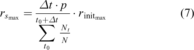
in the current keyframe to pick up stable and uniform distributed visual features for the VO, and keyframes are selected depending on the number of stable visual features and the parallax between the current keyframe and the last keyframe. Another use is the interaction with the surfel generation module, visual information is heuristic to assist surfel radius range adjustment in various scenes as it contains more details about the surroundings than the lidar point clouds. We have discussed that surfel radius represents the stability of the lidar measurement, the surfel radius range is increased in the feature-less environment for the reason that ICP is hard to converge in these scenes, and surfels need to be frequently updated according to (8) in runtime to handle LO’s degradation. Otherwise, we do the reverse operation to decrease the surfel radius range in well-structured scenes. Figure 3 can be used to explain the phenomenon. To maintain real-time performance, N is used as the maximum to restrict the number of visual feature, Nt
is the number of valid visual features in the frame received at the timestamp t and we define valid visual features as features that could obtain depth from the lidar points projection module. The environment state judgement module is activated once in a fixed time period

Surfels generated by EALVIO in different scenes. The upper pictures show the surfels generated in the corresponding lower scenes. The color represents the stability of surfels, yellow means stable, whereas green means unstable. The left column is a well-structured scene, and the right column is a feature-less scene. We can see that there exist more stable surfels in the right scene so we need to increase the surfel radius range for a better update of stable surfels. EALVIO: efficient and adaptive lidar–visual–inertial odometry.
A surfel map is composed of the surfels of recent lidar scans, and a map updating strategy is considered to update the old surfels and add new surfels to maintain a stable local map. The corresponding surfels of a lidar scan and the local map are matched by utilizing the vertex map V and normal map N; when a couple of matching surfels are found, we compare the radius of them; and if the new surfel radius

Table 1 presents the translation and rotation error of poses estimated by the SuMa system, which uses a fixed surfel radius range in the KITTI odometry data set 25 ; as the surfel radius range varies, the final accuracy will change a lot, which indicates that an unsuitable surfel radius range may weaken the performance of LO using surfels. To this end, as an adaptive sensor-fusion odometry, the surfel radius range changing mechanism is necessary for EALVIO since there is no need to tune the range in different environments manually.
Average translation and rotation errors of poses evaluated by SuMa with different maximal surfel radius range in KITTI odometry data set.
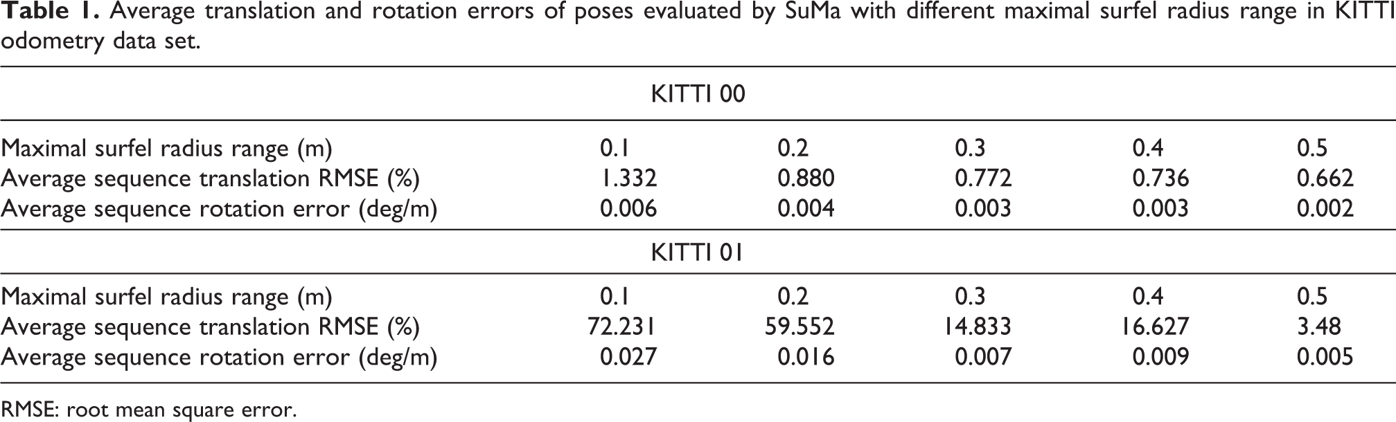
RMSE: root mean square error.
Visual odometry
We leverage the tightly coupled framework of VINS 11 to handle visual information and inertial information. The details of the camera pose estimation can be seen in their article. Here, we mainly introduce how the visual–inertial odometry cooperates with other modules of EALVIO.
It is known that there exists the problem of scale-drift
12
in pure VO due to the lack of feature depth information. IMU could help solve the problem as it can provide 6-DOF pose transformation in a short time period, but IMU bias and white noise are also introduced into the system at the same time. Although VINS has tried to eliminate the effect of IMU’s uncertainty, it is still a challenge work to offer a good initialization for the visual–inertial odometry with a large IMU bias. In EALVIO, the VO uses LO’s output integrated with raw IMU information as an initialization because LO always has a stable pose estimation in different scenes. We use a factor graph
26
to integrate LO and the IMU measurement in the IMU integration module, and the merged pose information contains the transformation between two consecutive images recently and the bias of IMU measurement, which are required in the VINS system. VINS maintains a sliding window composed of a series of state vectors to perform visual–inertial alignment and bundle adjustment. The full-state vector


When a visual picture comes at a time instant t, the position of the visual feature in the camera frame can be obtained. Since the visual feature only has a two-dimensional position, we reuse the vertex map VM
provided by the surfel generation module to perform feature-depth association. We set the z value of the visual feature to a unit and then project the visual features from the camera frame to the lidar frame through the transformation matrix

After calculating by (11), we get the position

Feature depth association. (a) Visual feature in the camera frame, we set the depth to the unit. (b) The visual feature transformed from the camera frame to the lidar frame. (c) The visual features are projected into sphere coordinate to find the corresponding depth in VM
, and VM
is transformed from W to Lt
in advance using
A non-linear bundle adjustment based on probability is performed to minimize the residuals of visual and IMU measurements, and the VO can finally provide a maximum posterior pose estimation together with a timestamp for the LO module as an initialization. Since LO and VO are asynchronous in output frequency, we need to leverage the timestamp checking and correction module to modify the VO output finely. If the VO provides an initialization
Surfel-based LO with adaptive ICP initialization
We leverage a surfel map to perform frame-to-model ICP to estimate 6-DOF lidar poses during the time period between two consecutive lidar scans. The ICP cost function E is based on point-to-plane errors

A surfel map contains a vertex map VM
and a normal map NM
of recent lidar scans. The right-upper index n represents the ICP iteration times. Vt
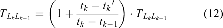
represents the vertex map of the current scan. We iteratively optimize the increment
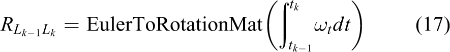
In well-structured environments, a reasonable pose increment given by the VO in (12) is the best choice to initialize ICP, whereas in feature-less areas, where VO may degrade, the IMU pre-calculation module provides a coarse pose increment for the ICP initialization using the high-frequency IMU raw data. Firstly, we estimate the lidar velocity by utilizing

Then, the increment between the current lidar scan Lk
and the last lidar scan


where
The increment is defined as

The following criteria are used to decide which pose increment can serve for the initialization of ICP, Nt
is the number of the stable visual feature mentioned in the visual-feature detection module used to measure the quality of VO’s output,
①
②
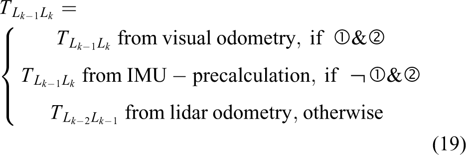
Finally,

Experiments
We implement the EALVIO utilizing c++ and ros-kinetic on a low-cost laptop, which has an Intel i5-9300 H CPU @2.4 GHz and an 8 GB RAM. The data sets are taken from two sources, one is from the data set gathered by LVI-SAM’s 14 author using a Velydone-16 lidar, a fish-eye camera and a MicroStrain IMU, and the other one is made by self-gathered using a RoboSense-16 lidar, a mono camera and an LMPS IMU in several agricultural environments. We run the EALVIO in these data sets to evaluate the accuracy of estimated poses and the efficiency and robustness of the system in real time. In addition, Lego-LOAM, LIO-SAM and LVI-SAM are mainly taken as the comparative sensor-fusion odometry systems.
Ablation study
To validate the methods and the strategies we presented in EALVIO, the following experiments are done to analyse the corresponding function and performance.
Ablation study of changeable surfel radius range
We disable the surfel radius range changing mechanism in EALVIO and use a fixed range to do a contrast test in the garden data set, the garden data set is provided by LVI-SAM’s author carrying handheld devices in a large garden where GPS signal is poor. The bird-eye view of the corresponding trajectories evaluated by different methods is shown in Figure 5. Since the data set starts and stops at the same position and GPS ground truth is not available, the end-to-end translation and rotation errors are computed to evaluate the accuracy in Table 2. We found that the surfel radius range changing mechanism enhances EALVIO’s adaptability to environmental change and reduces 82% of the translation errors in the 2 km garden data set, which is long term. The surfel radius range’s changing process in the garden data set during run time is shown in Figure 6; with the change in the surrounding environment, the surfel generation module of EALVIO can always choose the suitable surfel radius range under the support of the visual-feature detection module and the feedback of lidar state. Utilizing these adaptive surfels, the ICP methods of LO can have better estimations of agricultural UGVs’ poses.

Trajectories of garden data set evaluated by different methods.
End-to-end translation and rotation errors of garden data set.

EALVIO: efficient and adaptive lidar–visual–inertial odometry; IMU: inertial measurement unit; LVI-SAM: lidar–visual–inertial odometry via smoothing and mapping; LIO-SAM: lidar–inertial odometry via smoothing and mapping; Lego-LOAM: lightweight and ground-optimized lidar odometry and mapping.
The bold emphasis represent the optimal value of the corresponding index.

The surfel radius range changing process of EALVIO as time flows of the garden data set. The pictures are the visual features at the corresponding time; the green points represent the stable features, whereas the red ones are unstable. From the pictures, we can see that the more unstable visual features could result in a bigger surfel radius range. EALVIO: efficient and adaptive lidar–visual–inertial odometry.
Ablation study of VO
The VO is disabled to analyse the function of visual information on EALVIO, and the system is actually turned into LIO. The trajectories estimated by EALVIO without VO can be found in Figure 5, and the corresponding end-to-end errors are presented in Table 2. The EALVIO without VO leads to a large translation error when compared with the complete framework because VO can offer better pose estimations for the initialization of LO in well-structured environments containing adequate stable visual features, especially in these agricultural scenes where the ground is bumpy with few geometry features; VO plays a key role for localization.
Ablation study of IMU
Both IMU and VO are disabled in the ablation study of IMU because the VO in EALVIO cannot work individually without IMU integration; the system is simplified to pure LO. As the LO cannot get reliable initialization for surfel-based ICP in the scenes where LO may degrade a lot, the accumulated error of translation and rotation of the LO may become unbearable. However, on the other hand, the pure LO will not break down during the whole estimation procedure in the garden data set; hence, it is a good choice to run at the bottom of EALVIO to maintain robustness.
Comparison with state-of-art methods
Lego-LOAM, LIO-SAM and LVI-SAM’s results without loop-close are also invoked as contrast algorithms, and the loop-closure in these methods is disabled because loops may not be detected in many agricultural environments. Lego-LOAM is the representation of a loosely coupled lidar–inertial fusion system, and LIO-SAM is the representation of tightly coupled odometry; in the garden data set, they perform similar accuracy lower than LVI-SAM and EALVIO due to the lack of visual information support, and they may also fail to estimate the sudden and frequent rotation of UGVs. The complete EALVIO can reduce 74.08% of the translation error and 17.49% of the rotation error in the garden data set when compared with LVI-SAM without loop-closure, which is the newest state-of-art algorithm.
Many comparative experiments are also done in the handheld and jackal data sets of LVI-SAM, the handheld data set, which is feature-less, is gathered by handheld devices and the jackal data set, which is feature-rich, is gathered by a UGV called jackal, both data sets start and end at the same position. The trajectories evaluated by different methods compared with GPS ground truth are shown in Figure 7, and in Table 3, the average sequence translation root means square error (RMSE) with respect to GPS is computed to analyse the performance to restrain drift, and the end-to-end error is computed to analyse the accuracy. The results show that EALVIO can perform better accuracy and robustness in handheld data set when compared with the other three methods as it can handle the frequent environmental change in feature-less areas, whereas in well-structured scenes of jackal data set, LIO-SAM achieves the lowest translation RMSE as it makes better use of geometric features, but EALVIO can still achieve similar performance with state-of-art methods.

Trajectories of handheld and jackal data sets evaluated by different methods compared with ground truth. The upper pictures are trajectories evaluated in the handheld data set, the lower pictures are trajectories evaluated in the jackal data set, the GPS ground truth in the jackal data set may drift in some regions, which indicates the GPS signal is poor, and we discard the results of these regions in the following analysis. GPS: global positioning system.
Analysis of trajectories of handheld and jackal data set evaluated by different methods.

EALVIO: efficient and adaptive lidar–visual–inertial odometry; RMSE: root mean square error; LIO-SAM: lidar–inertial odometry via smoothing and mapping; LVI-SAM: lidar–visual–inertial odometry via smoothing and mapping; Lego-LOAM: lightweight and ground-optimized lidar odometry and mapping.
The bold emphasis represent the optimal value of the corresponding index.
Real-time performance analysis
The average processing time per lidar scan is measured to evaluate the real-time performance of EALVIO when compared with the other state-of-art sensor-fusion systems. As the odometry receives lidar point clouds at a constant rate in real time, we record each time period between the scan inputs and the corresponding odometry outputs. The results in Figure 8 show that the average processing time of EALVIO is 0.12s shorter than LVI-SAM in the garden data set tests, which means the real-time performance is around three times stronger than the LVI-SAM when performing a similar accuracy of pose estimation. We can also see from the figure that Lego-LOAM costs the least time when compared with other methods, but the odometry of Lego-LOAM relies on the mapping process costing additional time running in the backend of the system to modify pose estimation finely with a low frequency. In addition, since we do not use much nonlinear optimization and turn to the different initialization of ICP to fuse poses from different sensors, it is rare that the optimal solution of fused poses costs a long time to be obtained, and the processing time of each lidar scan is closer to each other in EALVIO than the other methods. We also accelerate the data set playing rate twice of its original rate and find EALVIO works well in the additional supplementary video.

Processing time of different methods in the garden data set.
Robustness in various agricultural environments
The robustness experiments are implemented by applying EALVIO to the real agricultural scene to examine the adaptability along with environmental change. Several typical agricultural scenes (greenhouse, fields and factory buildings) are considered in our experiments. The greenhouse and field scenes are challenging for sensor fusion systems as they contain bumpy roads, flat fields and bare farmlands, which may cause sensors’ degradation, and the factory buildings scene is utilized to examine the performance of EALVIO in well-structured areas as it contains distinct geometric features and good road conditions. The robustness of EALVIO is evaluated by computing the trajectories translation error and rotation error with ground truth utilizing the methods proposed by Geiger et al. 25 Figure 9 shows that EALVIO can provide UGVs’ trajectories estimated in different scenes, and Table 4 presents the corresponding errors. In addition, LVI-SAM’s performance in our data sets is also included in Table 4 as a contrast algorithm. In greenhouses, where the GPS signal is totally blocked, the ground truth is provided by the UWB module, whereas in fields and factory buildings, real-time kinematic global positioning system can be regarded as ground truth. We find that the average translation and rotation errors increase as the trajectories length grows, but they stay at an acceptable small range in different environments, which means EALVIO could maintain robust in most agricultural scenes, and the accuracy of pose estimation will not change dramatically in different scenes profiting by the surfel radius range changing and the adaptive initialization of ICP. In greenhouses and fields, which are typical agricultural scenes, EALVIO outputs better pose estimation than LVI-SAM according to the indicators in Table 4. In addition, in the well-structured factory buildings, EALVIO can also achieve a similar performance of accuracy and robustness of state-of-art methods.
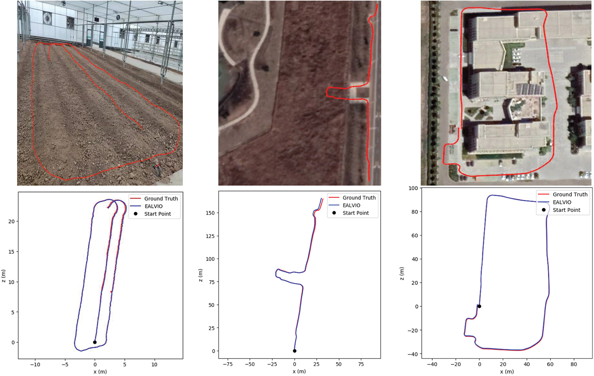
Trajectories evaluated by EALVIO in various agricultural scenes compared with ground truth (greenhouse, fields and factory building from left to right). EALVIO: efficient and adaptive lidar–visual–inertial odometry.
Average translation and rotation errors of trajectories evaluated by EALVIO and LVI-SAM compared with ground truth in various agricultural scenes.

The bold emphasis represent the optimal value of the corresponding index.
EALVIO: efficient and adaptive lidar–visual–inertial odometry; RMSE: root mean square error; LVI-SAM: lidar–visual–inertial odometry via smoothing and mapping; UWB: ultra-wideband; RTK-GPS: real-time kinematic global positioning system.
The bold emphasis represent the optimal value of the corresponding index.
Conclusion and future work
In this article, we proposed a sensor-fusion odometry system framework, which can output agricultural UGVs’ poses in various agricultural environments by combining three kinds of sub-odometry. To maintain real-time performance, we utilized efficient LO based on surfels to boost the pose estimation process, we also delivered a surfel radius range changing mechanism to increase the accuracy of EALVIO and the adaptive ICP initialization is used to fuse the odometry from multi-sensors and maintain the robustness of pose estimation. From the experiments, we can see that EALVIO performs better efficiency and similar accuracy in open data sets compared with LVI-SAM, which is one of the state-of-art sensor-fusion SLAM systems, and it also shows the advantage of adaptability as EALVIO can stay accurate and stable in various agricultural environments for a long term. However, EALVIO may be slowed as it relies on VO, which is based on visual-feature detection; in future work, we tend to use direct VO like direct sparse odometry 30 without detecting visual geometry features, and the real-time performance will be improved further.
Footnotes
Authors’ contributions
Conceptualization: Zixu Zhao; Methodology: Zixu Zhao; Software Programming: Zixu Zhao and Zaiwang Lu; Data Curation: Zixu Zhao, Zaiwang Lu, Long Long and Yucheng Zhang; Validation: Zixu Zhao, Zaiwang Lu and Long Long; Writing– Original Draft: Zixu Zhao; Writing– Review and Editing: Long Long, Yucheng Zhang and Jinglin Shi; and Supervision: Yucheng Zhang and Jinglin Shi.
Declaration of conflicting interests
The author(s) declared no potential conflicts of interest with respect to the research, authorship, and/or publication of this article.
Funding
The author(s) received no financial support for the research, authorship, and/or publication of this article.
Supplemental material
Supplemental material for this article is available online.
References
Supplementary Material
Please find the following supplemental material available below.
For Open Access articles published under a Creative Commons License, all supplemental material carries the same license as the article it is associated with.
For non-Open Access articles published, all supplemental material carries a non-exclusive license, and permission requests for re-use of supplemental material or any part of supplemental material shall be sent directly to the copyright owner as specified in the copyright notice associated with the article.