
Abstract
Visual servoing is a key approach to achieve visual control for the rotor unmanned helicopter. The challenges of the inaccurate matrix estimation and the target loss restrict the performance of the visual servoing control systems. This work proposes a novel visual servoing controller using the deep Q-network to achieve an efficient matrix estimation. A deep Q-network learning agent learns a policy estimating the interaction matrix for visual servoing of a rotor unmanned helicopter using continuous observation. The observation includes a combination of feature errors. The current matrix and the desired matrix constitute the action space. A well-designed reward guides the deep Q-network agent to get a policy to generate a time-varying linear combination between the current matrix and the desired matrix. Then, the interaction matrix is calculated by the linear combination. The potential mapping between the observation and the interaction matrix is learned by cascading the deep neural network layers. Experimental results show that the proposed method achieves faster convergence and lower target loss probability in tracking than the visual servoing methods with the fixed parameter.
Introduction
Visual control is a hot topic in the rotor unmanned helicopter field. 1,2 Visual servoing control (VSC) is a key approach to control the rotor unmanned helicopter from the initial position to the desired position by vision-based feedback. 3,4 A rotor unmanned helicopter is driven by the feedback of perceptual signals acquired from different visual sensors during visual control. Some advantages of rotor unmanned helicopters are operating flexibility, fast movement, and so on.
There are three types of visual servoing (VS) methods for rotor unmanned helicopters, which are 2D VS controller, 5 3D VS controller, 6 and 2.5D VS controller. 7,8 The 3D visual methods define the feature errors in the Cartesian coordinate system. It depends on the geometric model of the target, the depth estimation of red, green, and blue (RGB) images, and the camera’s internal parameters. 9 A point cloud model is an excellent approach to constructing a geometric model. 10 In practice, the performance of the 3D visual methods is greatly affected by the geometric model, camera parameters, system noise, and so on. Compared with 3D methods, the 2D visual methods directly use the position of feature points on the image plane as feedback for driving the rotor unmanned helicopter toward the desired position. One of the biggest advantages of this method is that it does not estimate the geometric model and camera parameters. The 2.5D VS controller can change between 2D VS and 3D VS. However, different environments require different switching rules, and the 2.5D controller is difficult to generalize. The proportional–integral–derivative (PID) controller is an excellent visual controller. The previous work demonstrated that the VS controller performs better than the PID controller in the hovering control task of the rotor unmanned helicopter. VS controller is an essential tool to achieve visual control. 11,12 However, some unavoidable factors should be considered, which may be the direct cause of the failure of a 2D visual controller, such as the singularity of matrix estimation. This brings unprecedented opportunities and challenges to the research of VSC. 12 –15 Control parameters of VS are key to addressing these challenges. But empirical parameters often cost a lot of time and labor costs. This work leverages deep reinforcement learning (DRL) tools to develop an adaptive VS controller for the VS of the rotor unmanned helicopter. The developed controller does not need to manually adjust the interaction matrix parameter.
Reinforcement learning (RL) is a potential approach to develop advanced VS controllers, and it has been demonstrated to have great potential to develop more advanced intelligent robotic systems. 16,17 Mannucci et al. 18 proposed a new RL approach to the visual controller for practical exploration. Then, two specific algorithms with this approach are presented to handle a dynamically complex control task for a mobile robot. In Xi et al., 19 an adaptive model with RL is developed to achieve stable gait behavior planning for a humanoid robot on a rotating platform. An optimization strategy is proposed to avoid overfitting problems. Besides, RL has been used to develop VS systems, and some interesting works have been proposed. Meng Kang et al. proposed an integrated VS method with the extreme learning machine and Q-learning to address the control gain that is heuristically a constant. 20 This control gain is adjusted adaptively by a determined policy. However, these adaptive visual control methods encounter bottlenecks because they are defined in the low-dimensional space.
Recently, achievements in deep learning provide an opportunity to achieve more advanced feature extraction to obtain high-dimensional features from perceptual data. 21,22 DRL uses the computational power of deep learning models to address the curse of dimensionality, and it can learn a mapping in an end-to-end way. In Sampedro et al., 23 the authors developed a VS controller with DRL to achieve direct mapping from state space to velocities for the mobile robot. Gazebo-based simulation has demonstrated the outstanding performance of this DRL controller. Deep Q-network (DQN) is a popular DRL algorithm for robotic control. Some previous works have used DQN to address the visual tracking control task. Most of these methods are implemented in an end-to-end manner. In Chen et al., 24 an end-to-end DQN controller is designed for the pursuer and evader problem of unmanned aerial vehicle (UAV). The end-to-end DQN control scheme is verified in simulation experiments. In Liu et al., 25 the tracking control problem of UAV is investigated, and the trajectory of UAV is designed adaptively by DQN. Villanueva and Fajardo 26 develop a DQN-based approach to the path planning and navigation of UAV, and the method’s effectiveness is demonstrated by simulation. The end-to-end DQN controller is used to achieve the tracking control, and it has been proved to have good control performance in simulation. However, the end-to-end DRL method is not well interpretable. There is still no literature to use DRL to design a VS controller for rotor unmanned helicopter. 27
In addition to DRL, deep learning has also been a hot tool for VSC systems. The previous work uses a deep learning network to achieve image processing in servoing system to achieve reactive control. In Bateux et al., 28 the author uses a deep neural network (DNN) to estimate the relative pose between the current image and the desired image. Meanwhile, the DNN can also handle the disturbance and lighting variations in the image. In Tran and Lin, 29 a convolution neural network model is designed to realize semantic segmentation on RGB images and pose estimation. The object information is used to realize VSC. Deep learning-based methods play an essential role in visual processing. Deep learning is mainly used in visual processing, which can be used in controller design combined with RL. The issues encountered by VS methods mainly focus on controller optimization and image processing to reduce the probability of the target being lost. Conventional VS controllers fail when there is a wide gap between the current pose and the desired pose. Practical matrix estimation may address this dilemma. Traditional methods often used the empirical value for the control parameter to approximate the interaction matrix. 7 It is appropriate to give a bigger control parameter value to ensure stable convergence when a rotor unmanned helicopter is close to the desired position. Instead, faster convergence is achieved with a small control parameter when the robot is far away from the target. 30 Therefore, a bigger parameter ensures stable convergence but not fast motion. Small parameter guarantees fast motion but cannot guarantee stable convergence. Previous work 31 has used the fuzzy method to estimate the parameter for the interaction matrix to achieve stable visual tracking control but the performance of this method is limited due to the empirical rules for the fuzzy method.
Previous work applied DRL to learn VS end-to-end directly. This kind of method directly learns the linear velocity and angular velocity in 3D space from the raw observation, which not only needs to handle the high-dimensional state and action space but also the reward function is difficult to design. Meanwhile, the high-dimensional continuous observation and action space make it easier for DRL to encounter low sample efficiency, thus requiring a longer learning time. In this article, we use DRL to learn the empirical parameter of the interaction matrix in VS, instead of end-to-end learning. DRL is used as an auxiliary control method to improve the performance of the existing controller, which does not require learning an end-to-end control policy directly from raw observations. Therefore, a relatively low-dimensional observation and discrete action space can achieve a good VS effect. Two neural networks characterize the DQN algorithm, and the current and the target networks produce control actions when performing a task. Then, appropriate action is selected using the trained policy to improve the performance of the VSC system. Faster learning ensures that rotor unmanned helicopters accomplish a task in time. Faster movement means that the rotor unmanned helicopter will be more efficient in completing the defined task. This work has made the following contributions. An intelligent VSC method using DRL is proposed. This method selects the time-varying interaction matrix in the VS controller. The adaptive VS with a DQN is used for visual control of rotor unmanned helicopter. The advantages of the DQN are employed to learn a mapping from the image features into the interaction matrix. The velocities of UAVs are obtained through the interaction matrix. The experimental results demonstrate that the proposed method obtains a VS controller with faster convergence. The improved VS controller also achieves a lower target loss probability during a visual tracking process.
This article is organized as follows. The second section presents details of the proposed method. The third section demonstrates the experimental results. In the last section, the conclusions are presented.
Methodology
In this section, we first show the framework of the proposed method. Secondly, we show the VS controller for rotor unmanned helicopter. Next, we show the DQN and the training method. The DQN will train the VS controller to select the time-varying control parameter for the interaction matrix.
The framework for the proposed method
This work develops an adaptive VS controller integrating DRL for rotor unmanned helicopters. A DQN algorithm is used to determine the parameter of the interaction matrix for VS. This method can ensure the fast convergence of the VS controller, thereby ensuring that the target can be quickly kept in the camera’s field of view. The proposed method is based on the DNNs that progressively learn the control behavior of the previous tasks. The framework for the proposed method is shown in Figure 1.

The framework for the proposed method.
Rotor unmanned helicopter captures the image information for the objects via an RGB camera. The current image features
VS for rotor unmanned helicopter
In this subsection, we show VS for rotor unmanned helicopters.
Figure 2 describes an imaging model, which maps the coordinate for the origin O on the Cartesian coordinate system into the coordinates for the origin O
1 on the image plane. dx
and dy
are scaling constants from the camera plane to the image plane in the x-axis and y-axis directions, respectively.

An imaging model.
If a point

where f is the focal length of the camera. The rotor unmanned helicopter gets an image from the environment using a camera. The vector

Then, the errors

The feature error

where
where
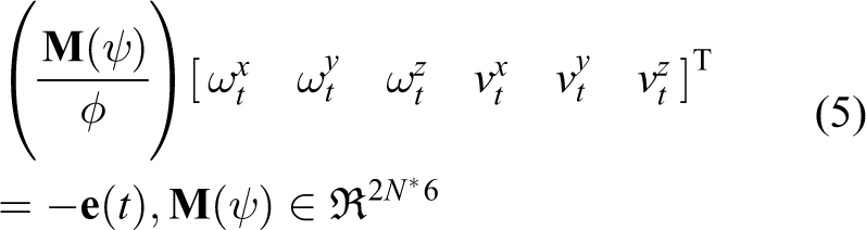
Considering the dynamic characteristics of the rotor unmanned helicopter, when the rotor unmanned helicopter flies nearly straight with the ground, the influence of pitch angle and roll angle can be removed by attitude adjustment. In a low-speed state, the influence of a small attitude tilt angle on vision can be ignored, and the pitching angle and roll angle will not be generated due to visual calculation. So, we can ignore the influence of the roll and pitch angles and only consider the linear velocity and yaw angles. The 6D velocity vector can be simplified to a 4D velocity vector.
The expression for the interaction matrix concerning the

The expression for the interaction matrix of the N features is
Deep Q-network
The DQN has two kinds of neural networks: the target neural network and the current neural network. The two kinds of neural networks have the same three-layer structure. The parameters of the current neural network are updated through the back-propagation. The parameters of the target neural network are updated each

The framework for the DQN algorithm. DQN: deep Q-network.
The DQN network is trained with the state action reward state action (SARSA) algorithm. SARSA algorithm is an improved Q-learning algorithm, and it is an on-policy RL algorithm, which iterates the value function in a strict Time Difference form. 34 Different from the classical Q-learning, SARSA still adopts a greedy strategy to select actions in the next state. The SARSA algorithm has a faster convergence rate in some specific control tasks than the classical Q-learning algorithm.
The SARSA algorithm selects the action with the current state st
according to the greedy strategy. After the action pt
is executed, it will be transferred to the state

We set
The neural network used in this article has a three-layer structure. The first layer is the input layer, the second layer is the hidden layer, and the third layer is the output layer. The classical RL algorithm stores the value function in the form of a table, but this method cannot solve the large-scale state space problem. The neural network has a strong generalization ability, which can approximate the value function

where
Training model
State space partition is the key component of developing the DRL model. The state space is given by

where

The action is given by

The updating law for the control parameter is given by

where
The reward function is divided into three parts: reaching the desired position, missing the target, and other situations. If the feature errors are less than the threshold value

where
Experiments and analysis
In this section, we first introduce the experimental preparation, including the testing platform and experimental arrangement. Second, we introduce the training of DRL. Third, we compare the proposed VS controller and the fixed-parameter VS controller. Fourth, we show the transferability of the proposed controller with DRL. The proposed VS controller can perform well on other tasks through fine-tuning. Finally, we apply the proposed VS controller to visual tracking and show the relevant results.
Experimental configuration
The rotor unmanned helicopter learns the action policy using the DQN algorithm. Based on the feature errors, the learned policy can be the transition to complex task scenarios with a modicum of works on tuning the parameters. In the experiments, the difference between the proposed method and the conventional VS controllers to estimate the interaction matrix is determined to test whether the proposed method allows better performance. Conventional visual control methods usually set the parameter of the interaction matrix manually. Therefore, the conventional methods use fixed parameters in the interaction matrix for VS. We intend to verify that DRL can improve the performance of the visual controller by automatically adjusting the parameter of the interaction matrix.
Simulation experiments are conducted on commercial robotic software, Gazebo 7.0. Inspired by the previous work, 35,36 we design the relevant simulation experiments. Figure 4 shows the simulation environment. The renowned robot operation system (ROS) is used for rotor unmanned helicopters. 37 The targets are four circles with different colors on the ground. The experiment is performed on a laptop, using only the CPU.

Experimental scene. (a) Visual servoing and (b) tracking. On the left is the hovering control for a rotor unmanned helicopter. The desired position is above the target. The rotor unmanned helicopter takes off from the initial position, flies above the target, and hovers there. On the right is the tracking task for a rotor unmanned helicopter.
The experiment is divided into three parts. The first part shows the training rules and training process of DRL. The second part shows the comparison between the proposed VS controller and the controller with fixed parameters and demonstrates that the proposed controller can be generalized to different scenarios through fine-tuning. The second part is to verify the effect of the proposed method by hovering control experiment. The third part shows the performance of the proposed controller and the controller with fixed parameters in a visual tracking task.
Training for RL agent
We show here the experimental parameter configuration, training rules, and training results. The training process is conducted on the simulation platform. An episodic RL setting is used to train the RL agent. In each episode, the desired position is
Parameters for the DQN agent.
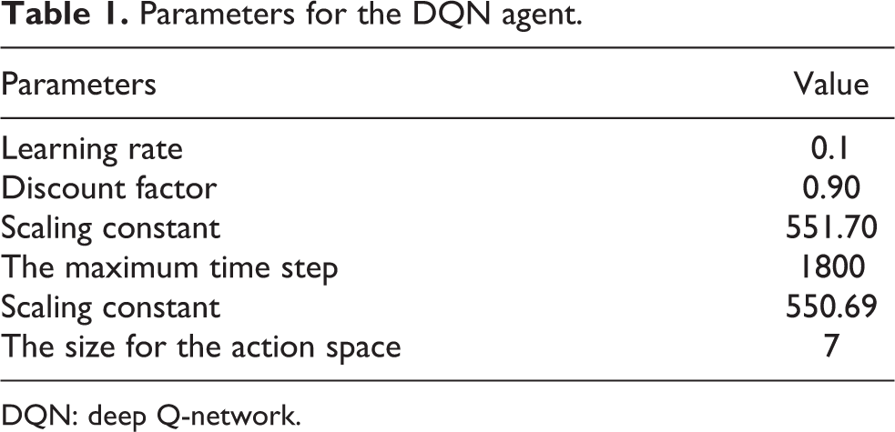
DQN: deep Q-network.
The rules for the DQN agent are as follows. (1) This episode is considered terminated if the rotor unmanned helicopter loses some features. (2) This episode is considered terminated if the errors between the current features and the desired features remain a certain pixel for a certain time. (3) This episode is considered terminated if the rotor unmanned helicopter does not arrive at the desired position after the maximum number of steps per episode. (4) After the DQN agent selects a new action, the interaction matrix is updated by equation (7). (5) If a new episode starts, the rotor unmanned helicopter returns to the starting position.
When this episode is terminated negatively, the reward of −100 is given to the DQN agent. In other episodes, the DQN agent is rewarded using the reward function. With this configuration, the learning process for the proposed method took about 6 h, and the agent learned a control behavior after episode 2000. The reward is a negative value per episode. Because the time for each episode is different, the average value of the control time for the learning process is recorded. The change in the control time for every 80 episodes is shown in Figure 5. Meanwhile, we compare an end-to-end VS controller based on deep deterministic policy gradient (DDPG). 23 DDPG maps image feature errors to the linear and angular velocities of the robot in the X, Y, and Z directions, respectively. VS can be achieved in an end-to-end manner. At the beginning of the training process, the DQN agent spends more time to complete the control task, and then the control time decreases with the number of episodes. Finally, after 2000 episodes, the average control time of the proposed method remained almost stable. However, the DDPG method converges at 2500 episodes. The DDPG method directly learns end-to-end linear and angular velocities from raw observations, which face a high-dimensional observation and action space. The proposed method learns in a relatively low observation and action space, thus requiring less training time. The proposed method converges faster than the end-to-end DDPG method.
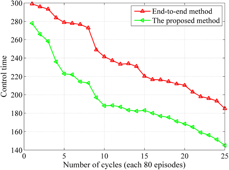
The curve for the control time of every 80 episodes.
Experiment on VSC
Hovering control requires rotor unmanned helicopters to fly from an initial position to the desired position and then hover at the desired position. Hovering control is used to test the convergence of the proposed method. The rotor unmanned helicopter always flies almost parallel to the ground. During the experiment, the range of roll angle and pitch angle of the rotor unmanned helicopter is within 5°, indicating that the roll and pitch angles can be ignored.
We set an initial position and a desired position on the ground for the hovering control. The rotor unmanned helicopter will not start to hover until 1.5 m away from the ground. There is a wide gap between the current position and the desired position in practice. When the rotor unmanned helicopter reaches the predetermined position and completes a control process, the current image is close to the desired image. The rotor unmanned helicopter perceives the object via the contour feature extraction algorithm in the experiment. It then achieves the closed-loop feedback and finally achieves effective tracking control. This subsection will demonstrate that the proposed method achieves faster convergence and smoother motion trajectory than the conventional methods with fixed parameters. Meanwhile, the proposed method achieves similar results as the end-to-end method, but less training time is required.
In this test, to verify the effectiveness of the proposed method, the proposed method and five competitors were run on the platform using a rotor unmanned helicopter. The initial position is

Comparison of the feature trajectories for the six VS schemes. (a) IM-0.1, (b) IM-0.3, (c) IM-0.6, (d) IM-0.8, (e) the proposed method, and (f) DDPG. VS: visual servoing; DDPG: deep deterministic policy gradient.

The curve of the velocities for the six VS schemes. (a) IM-0.1, (b) IM-0.3, (c) IM-0.6, (d) IM-0.8, (e) the proposed method, and (f) DDPG. VS: visual servoing; DDPG: deep deterministic policy gradient.
Figure 6 shows the feature trajectories for the six methods. Conventional methods cause one dimension to reach the desired position while others do not. So there are many fluctuations in the feature trajectory. The proposed method has the least fluctuation compared with the VS methods with fixed parameters. The proposed method enables the learning agent to learn a policy to produce the best solution to reduce fluctuation. Figure 7 shows the curve of the velocity for the six different methods. In Figure 7, the y-axes show the comparison results for six different methods, and the x-axes donate the control cycles. The trajectories for the four feature points are represented by the blue curve, the green curve, the red curve, and the wathet curve, respectively. Experimental results show that the IM-0.1 method converges in around 148 control cycles. The IM-0.3 method converges in around 179 control cycles, and the IM-0.6 method converges in around 250 control cycles. The IM-0.8 method converges in around 150 control cycles. The convergence time for the proposed method is around 120 control cycles. The DDPG method converges at 125 control cycles. Although the four conventional competitors reach the desired position, the convergence rates for the four competitors are slower than the time for the proposed method. Different methods estimate different interaction matrix, which results in different behavior for the control method for the rotor unmanned helicopter. The proposed method performs similarly to DDPG but requires less training time. In Figure 7, at the beginning of the control process, the VS system using the DQN algorithm chooses a larger velocity, which drives the rotor unmanned helicopter to reach the target position faster.
Experiment on the generalization of the proposed method
We added some Gaussian noise to the image. These Gaussian noises have a certain adverse impact on the feature extraction process, which increases the difficulty of the control task for the proposed method. In this work, to test the generalization of the proposed method, a knowledge transfer with fine-tuning is used to transfer the learning experience to more complex scenarios. The hovering task with a certain noise is configured as the complex scenes. Then, the learned experience of the previous task is utilized in the current task. Previous works investigate the application of the RL method on robots and combine it with a direct transfer method to achieve the knowledge transfer from a task domain to a similar task domain. 38,39 This work tests the effect of the DQN-based scheme with a fine-tuning and the DQN-based scheme with a direct transfer method (Direct Transfer). 38,39
Experimental results are shown in Figures 8 and 9. Figure 8 shows the feature trajectories for the two DQN-based schemes in a noisy environment. Noises affect the motion process of the DQN-based VS methods. The feature trajectories for two controllers with RL exhibit less fluctuation. The smoothest trajectory is achieved for the proposed method with fine-tuning. The experimental results demonstrate that the fine-tuning can better exploit transfer when the proposed method controller encounters more complex tasks. Figure 9 shows that the proposed method with a fine-tuning converges in around 170 control cycles and the proposed method with Direct Transfer converges after 200 control cycles. The results for velocities further demonstrate that the proposed method with a fine-tuning outperforms the conventional Direct Transfer method.

The curve of the feature trajectories for the two proposed method schemes. (a) Fine-tuning and (b) Direct Transfer.

The curve of the velocities for the two proposed method schemes. (a) Fine-tuning and (b) Direct Transfer.
Although the noise has caused some adverse impacts on these six methods, the proposed method still has a good result. Figure 10 shows the flying trajectories for the two schemes. The proposed method with Fine-tuning flies directly to the desired position after taking off and experiences little fluctuation. However, the proposed method with Direct Transfer has more fluctuation after take-off, not a longer flight path. The experimental results show that the proposed method can be well transferred through fine-tuning. The designed model can be generalized by fine-tuning, which means that the learning model can be transferred to other task scenarios. Next, we transfer the learning model to a visual tracking control task scene.

The curve of the flying trajectories for the two proposed method schemes. (a) Fine-tuning and (b) Direct Transfer.
Experiment on the tracking control
This section applies the control variable method to separately control the car’s linear velocity and angular velocity. With the increasing linear velocity and angular velocity, tracking becomes more and more difficult. We recorded the probability of the car being lost to compare the performance of different controllers in tracking.
In this experiment, the wheeled robot is used as the tracked target, and the tracking effect of the rotor unmanned helicopter under different methods is tested. To ensure that the rotor unmanned helicopter can get all the features of the target in the tracking control process, it is set that the rotor unmanned helicopter takes off to fly directly above the target 1.5 m before starting the tracking control experiment. This tracking scene has a certain noise. Each round of experiments has the same initial position and the desired position. The car starts from the initial position in each round and moves to the desired position at a constant speed. This will be recorded as a failed tracking when the car deviates from the helicopter’s camera field of view.
The tracking path of the rotor unmanned helicopter is shown in Figure 11. The rotor unmanned helicopter follows the car on the ground, from O1 to O4. In Figure 11, red indicates a rotor unmanned helicopter, and purple indicates a ground target. When the rotor unmanned helicopter loses the target, that is, the feature points deviate from the camera field of view, this episode is a failure. We record the number of failures every 10 episodes and calculate the probability of failure in the 10 episodes.
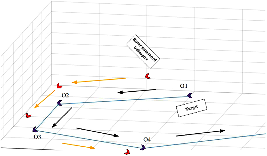
The motion paths for the rotor unmanned helicopter.
In the experiment, the control variable method is used to control the target to move at different linear velocities, with the linear velocity range from 0.2 m/s to 0.65 m/s. The rotor unmanned helicopter takes off tracking to ensure that the target’s angular velocity is the same, and the target moves at a different linear velocity. To avoid the contingency of the experiment, for each different linear velocity movement of the target, the rotor unmanned helicopter tracks for 10 times, which is calculated as the probability of not losing the target (keeping the target). With the increase of the velocity of the target, the probability of not losing the target using three different methods becomes smaller and smaller. Similarly, the linear velocity is fixed, and a certain range of angular velocity is used to test. The angular velocity ranges from 1.35 rad/s to 2.00 rad/s.
According to previous experimental results, the control effect of IM-0.8, IM-0.1, and the proposed method is better than other methods. Therefore, this experiment uses these three methods as a comparative method. In Figure 12, when the angular velocity is fixed, the probability that the three methods keeping the target will gradually decrease with the increase of linear velocity. However, the probabilities of the three methods are different for the same linear velocity. The proposed method has the maximum probability of keeping the target. Similarly, when the linear velocity is fixed, the probability of losing the target in the three methods will increase gradually with the increase of angular velocity. With the increase of angular velocity and linear velocity, tracking control becomes more difficult. Therefore, these three methods will lose targets. The proposed method has the least probability of losing the target, that is to say, the tracking effect is the best. The self-learning ability of DRL gives better tracking control performance. Experimental results show that the proposed method has a better tracking control effect.

The curve of the tracking results for the three methods. (a) Linear velocity and (b) angular velocity.
Time delay is a key issue in visual control systems. The time delay is often caused by the speed mismatch of image processing and command execution. In the actual experiment, the system delay is usually unavoidable, which causes some difficulties to the physical experiment. Especially when a RL model is transferred from the simulator to the real device, the physical system delay will make the DRL model difficult to be applied. The system delay will be investigated in the next research.
Conclusions
VS systems often encounter performance bottlenecks, such as converging slowly or target loss. RL holds the promise of enabling rotor unmanned helicopters to learn large repertoires of behavior manipulations with minimal human knowledge. This work developed a new adaptive VSC method that integrates DRL to control a rotor unmanned helicopter using only the image features. The DRL model is extended to more complex tasks using fine-tuning in the presence of more disturbances. To effectively handle the VSC challenges of the rotor unmanned helicopters, this work proposed a DQN-based RL scheme to estimate the interaction matrix with additional learning capability adaptively. The DQN networks are got using considerable training, and then these networks can automatically calculate an interaction matrix to achieve a robust control performance of the rotor unmanned helicopters. The proposed method has been extensively compared with four conventional methods, revealing the good capabilities of the adaptive control method.
RL has been a popular method to design the reactive control system for rotor unmanned helicopters, from the original tabular policy RL to DRL. 40 However, it still lacks an effective solution for the knowledge transfer from simulation to the real world. Meanwhile, there is a lot of noise and illumination in the physical environment, which interferes with training in the physical environment. Secondly, the system delay is more obvious in the physical equipment than in the simulator, which is an uncontrollable factor. The system delay will be more serious when dealing with high-speed moving targets. Many factors make it very difficult to complete visual control in the physical environment. Besides, the knowledge transfer of DRL from the simulation to the real world will be investigated.
Footnotes
Declaration of conflicting interests
The author(s) declared no potential conflicts of interest with respect to the research, authorship, and/or publication of this article.
Funding
The author(s) disclosed receipt of the following financial support for the research, authorship, and/or publication of this article: This work was financially supported by the Guidance Programs of Medical and Health Field of Science and Technology Funds of the Xiangyang city (2020ZD32).