
Abstract
Forestry monitoring and high-voltage cable inspection demand on low-cost climbing robots. The proposed climbing robot has simple control and low cost, enabling loaded, which drives by a single motor. Based on the overrunning spring clutch mechanisms, two motions of holding and climbing are realized by one motor. A rope-driven gripper is for adaptive enveloping holding effectively and a thron wheel is used to attach the climbing surface and stable climbing. The design parameters of the overrunning spring clutch mechanism and the rope-driven gripper are determined. The prototype and experiment setup are built. The enveloping holding experiment is carried out to verify the holding stability and shape adaptability of the rope-driven gripper. The trunk and pipe climbing experiments verify the climbing performance of the climbing robot and its application prospects with a certain load. In the future, as a low-cost climbing robot, a camera or operating mechanism can be equipped for tasks.
Introduction
In recent years, high-altitude and dangerous environments such as forestry, construction, and space environments have been typical application scenarios for special robots. Forest farm monitoring, high-voltage power transmission equipment overhauling, and spacecraft on-orbit maintenance have harsh working environments, high working intensity, and frequent accidents. 1,2 It is urgent to develop low-cost robots with climbing capabilities that are suitable for replacing humans in carrying out high-altitude and deep-space operations.
Climbing robots can be divided into three categories according to climbing attachment principles: Magnetic adsorption or electrostatic attachment: A certain attachment force is generated between the electromagnet or electrical adhesive sheet and the surface, so that the climbing robot is attached to the working surface. Due to magnetic
3
–8
or electrostatic force adsorption,
9
the climbing objects are mostly metal surfaces such as ship hulls and steel tanks. Pneumatic attachment: Pneumatic attachment is the suction force generated by suction cups or active suction devices to be adsorbed on the surface of the object. The climbing robot with a suction cup has a relatively small adsorption force and cannot be used in a heavy load environment, and a smooth adsorption surface is required.
10
–13
Active suction climbing robots have greater adhesion and can be applied to rough surfaces, but they are noisy.
14
–16
Both suction cup and active suction require a smooth climbing surface. Mechanical attachment: This attachment method mainly uses a holding device or a claw mechanism to generate adhesion, so that the climbing robot climbs on the surface of the object. This type of climbing robot is mostly used in the following three climbing environments: rods, surfaces with protruding structures, and rough surfaces.
17
–26
The mechanical attachment climbing robot can adapt to more complex environments and application scenarios. However, since the holding and climbing motions are carried out at the same time, more driving sources and complex control systems are required.
Climbing robots of magnetic, electrostatic, and pneumatic attachment are difficult to apply in nonvariable cross-section scenes such as trunks or cables. However, mechanical climbing robots have many drive sources and complex controls that also cause problems for practical applications. The overrunning clutch 27 brings the possibility of reducing the driving source. Overrunning clutches are often used in automated transmission applications, such as vehicle shifting, 28,29 joint torque transmission, 30 rotary actuators, 31 and so on. In these applications, overrunning clutches are used for excellent torque and speed control to achieve the required torque/speed stability. From the perspective of saving the number of driving sources, if the driving source is transmitted through a shaft, one side of the shaft is used for advancing, and the other side is connected by an overrunning clutch to obtain the desired torque for holding the trunk. Then, one driving source can be used for two movements, which will reduce the required drive source.
This article proposes a low-cost self-adaptive holding climbing robot driven by a single motor. Two motions of holding and climbing by a single motor are realized based on the overrunning clutch mechanism. The front overrunning clutch mechanism is used to achieve stable holding, and use the rear overrunning clutch mechanism to achieve climbing. The design parameters, overrunning clutch analysis, driving force are carried out. Finally, a prototype is developed and experiments on the climbing robot prototype are carried out to verify the self-adaptability and climbing performance.
Model design
Design for single-motor-driven climbing robot
Figure 1 shows the proposed CAD design of the climbing robot. The climbing robot is mainly composed of three parts: the thron wheel, the rope-driven gripper, and the overrunning spring clutch mechanism.

CAD design of the climbing robot. (a) Schematic mechanism of the proposed climbing robot. (b) Design of the thron wheel. (c) Design of the rope-driven gripper. (d) Design of the driven system.
The thron wheel is driven by the flexible shaft, where the torque is provided by a motor. The thron wheel is composed of 10 thron pieces, and partitions are installed between each thron piece, as shown in Figure 1(b). Each adjacent thron piece is staggered by 22.5° and fastened to the partitions with screws. Four claws are evenly distributed on each thron piece in a square shape. The throns are equipped at the end of each claw, and a spring is installed under the throns. The throns can be well embedded in the climbing surface during the climbing process. The design of the spring and the curved structure of the thron pieces reduces vibration and impact under pressure.
The rope-driven gripper, as shown in Figure 1(c), is installed on both sides of the climbing robot. Each side of the rope-driven gripper has two limbs driven by a driven rope. One end of the driven rope is fixed at the rope fixed end, the other end is fixed at the rope winding shaft, and the rope goes around two pulleys. When the rope winding shaft rotates, the driven rope is wound on the rope winding shaft, driving the deformation of the two limbs. Auxiliary wheels are installed on each limb to contact the climbing surface and move with the thron wheel. Return springs are installed at the joints of the limbs to ensure that the rope driving grippers can be restored to the initial straight state after holding climbing.
The overrunning spring clutch mechanism is shown in Figure 1(d). The motor provides torque for the motor input shaft through the reduction gear group. The front end of the motor input shaft is connected to the rope winding shaft through the front overrunning clutch to provide torque for the rope-driven gripper to ensure the holding movement. The rear end of the motor input shaft is connected to the flexible shaft connection shaft through the rear overrunning clutch, which provides torque for the flexible shaft to drive the thron wheel forward. The electromagnetic switch can control the connection between the flexible shaft and the flexible shaft connecting shaft.
Climbing strategy
The climbing strategy of the proposed climbing robot is shown in Figure 2. The climbing process is divided into a holding state and a climbing state.

Climbing process of the proposed climbing robot.
In the holding state, the motor and the electromagnetic switch are first powered on. At this time, the rear overrunning clutch is disconnected, and the front overrunning clutch is combined with the motor input shaft. The front overrunning clutch drives the rope-driven gripper to self-adaptive holding until it is stable. Then the front overrunning clutch overruns, and the rope-driven shaft maintains adaptive holding under the action of friction force and holding force.
The climbing stage starts when the electromagnetic switch is closed. The rear overrunning clutch is combined with the motor input shaft, and the thron wheel is rotated through torque transmission of the flexible shaft. The climbing robot starts to holding climb to the target position and then powers off. The climbing robot will maintain the holding state and stay at the target point for observation tasks.
Parameter analysis
Enveloping holding parameters
In the following parameter analysis, the design parameters will be demonstrated in detail, whose definitions are shown in Table 1.
Parameters definition.

Enveloping holding range
The stable enveloping holding state of the rope-driven gripper is five-point holding. The five points are shown by the red dots in Figure 3(a), and the blue dots are the contact points of the limbs. The enveloping holding range depends on the geometrical size of the climbing robot. The appropriate holding range is determined by designing the length of the base, first limb, and second limb.

Diagram of five-point holding. (a) Five-point holding. (b) Maximum enveloping holding. (c) Minimum enveloping holding.
For the five-point holding state, the rope-driven gripper is symmetrical on both sides. Taking one side of the analysis, there is the following identity

The length of limbs and base must satisfy the following relationship

From the geometric relationship, the rotation angle of one side of the first and second limbs can be obtained as follows


The maximum enveloping holding state of the rope-driven gripper is shown in Figure 3(b). When the second limb is in contact with the holding object, and the normal direction of the contact point is perpendicular to the y-axis, the theoretical holding radius r reaches the maximum value. At this time, the total angle between the limbs is 90°


The theoretical maximum holding radius r max can be calculated as

The minimum enveloping holding state of the rope-driven gripper is shown in Figure 3(c). It can be obtained from the geometric relationship that the sum of the angles between the first limb and second limb is 180°


Then, we get

Therefore, it has

The theoretical maximum holding radius r min can be calculated as

The relationship between the theoretical holding radius r and structure size is as follows

The rope-driven gripper determines the range in which the climbing robot can adaptively hold the object. According to the actual situation, L 0 = 55 mm, L 1 = 110 mm, L 2 = 70 mm, and the holding range is

Adaptive analysis
Adaptive climbing means that the rope-driven gripper can continuously adapt to external constraints. To ensure that the climbing robot can stably attach to the object during the climbing process, a five-point holding contact is formed between the gripper and the holding object. As shown in Figure 3(a), the external constraint equation of the rope-driven gripper is established based on the geometric relationship

The relationship between θ 21 and θ 22 without x 0 and y 0 can be obtained as

Assuming that the rope-driven gripper is not in contact with the holding object, the first limb and the second limb are coupled to move, and the winding displacement of rope a is determined by the rotation angle of the two limbs, which can be called the free motion equation

When the rope-driven gripper is not in contact with the object, the relationship between the first limb and the second limb is

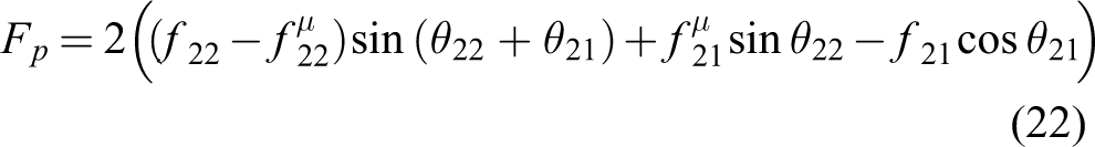
From the external constraint Equation (16) and the free motion Equations (17) and (18), the motion trajectory of the rope-driven gripper can be obtained with different holding radii as shown in Figure 4.
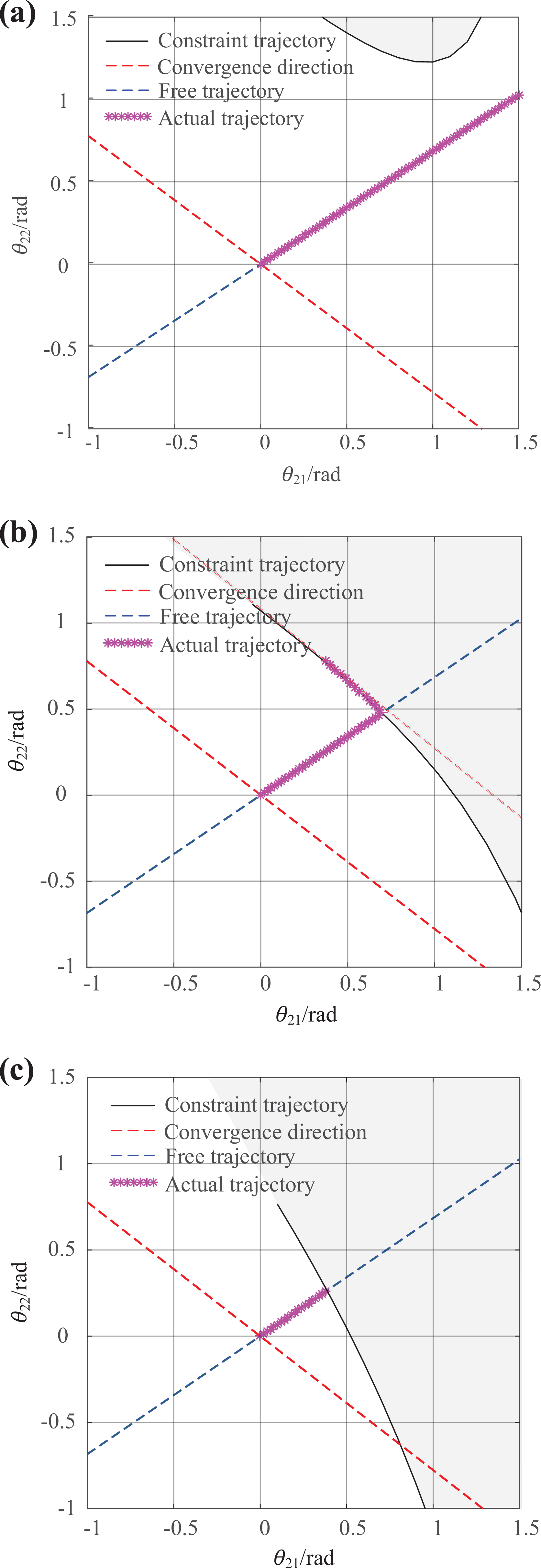
Movement trajectory of limbs under different holding radii. (a) r = 45 mm. (b) r = 60 mm. (c) r = 140 mm.
The black solid line represents the constrained trajectory, and the gray area represents the area where the rope-driven gripper cannot reach. The red dotted line is the convergence direction, the blue dotted line is the theoretical free trajectory, and the pink mark represents the actual motion trajectory of the rope-driven gripper.
When r = 45 mm, as shown in Figure 4(a), the radius of the holding object does not belong to the range of the five-point holding. The free trajectory does not intersect with the theoretical constraint trajectory. The rope-driven gripper will move on the free trajectory.
When r = 60 mm, as shown in Figure 4(b), the radius of the holding object belongs to the range of the five-point holding. The free trajectory intersects with the theoretical constraint trajectory. The rope-driven gripper will move on the free trajectory first. Then, the rope-driven gripper contacts the holding object, where the position in Figure 4(b) is the intersection point of the free trajectory and constraint trajectory. The rope-driven gripper will change the rotation angle of limbs along the constraint trajectory until the convergence direction is parallel to the tangential direction of the constraint trajectory. At this time, the limbs move to the convergence point, and the five-point holding reaches a stable state.
When r = 140 mm, the radius of the holding object does not belong to the range of the five-point holding. The free trajectory intersects with the theoretical constraint trajectory. First, the rope-driven gripper will move on the free trajectory. Then, rope-driven gripper contacts holding object. Since there is no tangent intersection point in the convergent direction of the constraint trajectory, the holding process cannot converge; that is, the climbing robot system is in an unstable five-point holding state.
Static analysis
Static analysis will provide theoretical support for motor selection and overrunning clutch design. Figure 5 shows the pathway of the force transmission of the rope-driven gripper. The input torque at the limbs is determined by the pulling force of the rope and the radius of the pulley. The friction torque on the limbs is negligible relative to the output torque. From the schematic in Figure 5, the output torque of the rope acting on the limbs can be calculated as follows

Schematic of the right limbs.

T 1 and T 2 are the output torques of the first and second limbs. When stable holding, the contact force between the limbs and the object is

Combining Equations (1), (19), and (20), we obtain the contact force of the limbs

The rope-driven gripper is a symmetrical structure. When holding stably, the normal force and friction force of the left and right limbs are equal. According to the static analysis, the positive pressure of the climbing robot can be obtained as
where

Thus
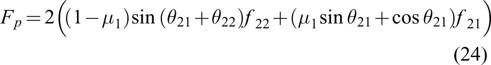
Figure 6 represents the relationship between positive pressure FP and rotation of limbs θ 21 and θ 22. The rotation angle of the limbs is in the range of 0 to 1 rad, and the positive pressure is −15 to −10 N.

Relationship between positive pressure and rotation angle of limbs.
The driving force of the climbing robot F is determined by the positive pressure FP and the sum of the gravity of the climbing robot and the load G

As a simplification, the static friction force is negligible due to its small value compared with the normal force. Thus

Through the estimation of the driving force, the torque of the motor can be effectively determined, which provides a reference for the design of the overrunning clutch.
Overrunning spring clutch mechanism parameters
Overrunning spring clutch mechanism principle
The single motor reduces the driving source of the climbing robot, greatly reduces the difficulty of robot control, and effectively reduces the manufacturing cost. The core of realizing single-motor drive is to use the combination and overrunning state of the overrunning spring clutch mechanism.
The overrunning clutch is mainly composed of an input shaft, an output shaft, a spring, and necessary supporting mechanism. The principle of the overrunning clutch is that the spring can contract or expand in the radial direction to transmit torque. It has two states, namely, the combination state and the overrunning state, as shown in Figure 7.

Principle of overrunning spring clutch mechanism. (a) Combination state. (b) Overrunning state.
The combination state is shown in Figure 7(a). When the input shaft turns in the same direction as the spring, the spring is wound on the input shaft and the output shaft in an interference manner. When the input shaft provides torque, the friction force causes the spring to contract and tightly connect to the output shaft, and the torque is transmitted from the input shaft to the output shaft. At this time, the input torque is equal to the friction torque, Mi = T 0. As the input torque increases, the friction force increases accordingly, and there is an ultimate combination torque MC . As the input torque increases, the internal force of the spring also increases. When the strength limit of the spring is reached, the clutch will fail because the spring is broken, which is the ultimate combination torque. Therefore, the combination state should satisfy that the input torque is less than the ultimate combination torque, Mi < MC .
The overrunning state is shown in Figure 7(b). The direction of the input shaft is opposite to that of the spring. There is an ultimate overrunning torque MO . When the input torque is larger than the ultimate overrunning torque, the spring expands and the output shaft slips, which results in the separation of the two shafts. The friction torque between the spring and the output shaft is not enough to drive the output shaft, that is, the overrunning state. At this time, the input torque Mi is greater than the friction torque T 0. The overrunning state should satisfy that the input torque is greater than the ultimate overrunning torque, Mi ≥ MO .
Rear overrunning clutch combination state analysis
The input shaft of the rear overrunning clutch is the motor input shaft, and the output shaft is the flexible shaft connection shaft, which is connected to the flexible shaft to transmit torque to the thron wheel. The connection between the flexible shaft and the flexible shaft connection shaft is controlled by an electromagnetic switch to realize the thron wheel stops or rotates. Therefore, the rear overrunning clutch only needs to meet the combination state, where the input torque is less than the ultimate combination torque, Mi < MC .
The ultimate combination torque in the combination process has a direct relationship with the effective number and the interference of the spring. According to the strength limit of the spring, design and calculate the effective number of springs n and the amount of interference ΔR.
The springs used are torsion springs with circular sections, and the ultimate combination torque is

where d is the spring diameter and [σ] is the permissible stress.
In the combined state, the theoretical model of the input torque is 27
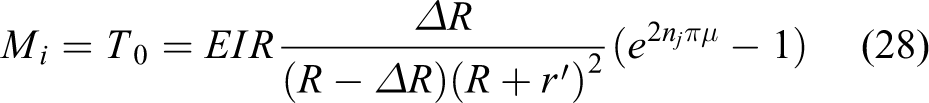
where R is the radius of the shaft, r′ is the wire diameter of the spring, nj is the effective number of the spring, and ΔR is the interference between the shaft and the spring.
When nj is small and the input torque is large, slipping will occur between the spring and the input shaft. The effective number of springs must meet the following conditions

Therefore, when the torque of the motor input shaft is determined, the effective number of spring nj is determined by the interference ΔR and the radius of the shaft R.
Front overrunning clutch overrunning state analysis
The input shaft of the front overrunning clutch is the motor input shaft, and the output shaft is the rope winding shaft. The rope winding shaft realizes the holding function by driving the rope-driven gripper by rope tensioning. After the rope-driven gripper achieves stable holding, the rope winding shaft separates from the motor input shaft, and the rope winding shaft slips. Therefore, the front overrunning clutch needs to realize the overrunning function.
When the front overrunning clutch is in the overrunning state, the ultimate overrunning torque is

When the input torque is greater than the friction torque, the output shaft slips, and the friction torque continues to drive the output shaft. At this time, the friction torque is 2 7

Therefore, the parameter design of the overrunning clutch can be designed according to the required input torque.
Design parameters of the climbing robot
The design parameters of the climbing robot are obtained in three steps. First, it clarifies the range of the target holding object and determines the size of the mechanical workpiece such as the rope-driven gripper and the base. Second, determine the required driving force according to the holding range, calculate the parameters of the front and rear overrunning clutches, and determine the size of the shaft and the spring. Finally, select the appropriate electrical components according to the driving force, such as motors, sensors, electromagnetic switches, and so on.
Experimental results
Experimental setup
The prototype is built with a variety of materials to ensure rigidity and reduce the total weight of the prototype. The main structural parts of the prototype are all made of 6061 aluminum alloy to ensure the rigidity of the prototype. The motor input shaft, rope winding shaft, and flexible shaft connection shaft are made of GCr15 bearing steel, which has good wear resistance and rigidity. The auxiliary wheel of the rope-driven gripper is 3D printed with nylon material, which has a large friction coefficient. The thron wheel is 3D printed with resin material, which has good ductility and extremely light weight. The detailed design parameters are shown in Table 2.
Parameters design.

The motor uses a Faulhaber RY2723, the rated torque is 1 Nm, and the required voltage is 12 V. The flexible shaft uses GEMO No. 100112. The electromagnetic switch is LAXXSCOM 6-6-10. The power supply selects 12 V batteries, which are installed inside the shell. The potentiometer has a resistance of 50 kΩ, the accuracy of 1%, and a sampling period of 1 ms, which is pasted on the rotation of the rope-driven gripper and thron wheel to collect the changes in the rotation angle.
Enveloping holding experiment
To verify the enveloping holding performance, an experimental platform was built as shown in Figure 8. The climbing robot holds a cylindrical object with a diameter of 80 mm. The potentiometers are pasted on the left limbs of the climbing robot. The data are collected through the PCI board, and the data are recorded and processed at the PC terminal. After polynomial fitting of the curve, the change curve of the rotation angle with time is obtained.

Enveloping holding experiment.
It can be seen from the curve that the first limb rotates faster than the second limb. This is because the joints of the limbs are equipped with return springs, which can absorb energy, resulting in a lag in the rotation of the second limb. The first limb reaches the maximum rotation angle of approximately 0.7 rad at 250 ms, and then the rotation angle rebounds. Finally, it stabilizes at 0.6 rad after 300 ms. The change in the rotation angle of the second limb is relatively stable, stabilizing at 0.45 rad after 500 ms.
The rebound of the first limb is due to the contact with the holding object, which changes the free holding trajectory. At this time, the second limb has not yet contacted the holding object. Subsequently, both the first and second limbs are in contact with the holding object. This moment is the inflection point of the actual trajectory in Figure 4(b). However, due to the existence of the return springs, a sharp change in the rotation angle that should have occurred does not appear. Under the common action of the rope and the return springs, the limbs smoothly hold the object and reach a stable state.
Most objects with noncircular cross-sections cannot form a five-point holding, and the left and right limbs are no longer symmetrical. The holding performance of noncircular section is tested by shape adaptability experiments as shown in Figure 9. Four kinds of holding objects with different cross-sections were produced by 3D printing, namely, the triangular section, the pentagonal section, the hexagonal section, and the irregular section.

Shape adaptability experiment. (a) Triangular section. (b) Pentagonal cross-section. (c) Hexagonal cross-section. (d) Irregular section.
When the sectional shape is symmetrical, as shown in Figure 9(a), (b), and (c), although the five-point holding is not formed, there is still a stable holding. However, when holding the object with left and right asymmetrical sectional shapes, there will be only one contact point on one side, as shown in Figure 9(d). At this time, the climbing robot will be in an unstable holding state, and the climbing robot will lean along the axis of the holding object and cannot complete the climbing.
Climbing experiment
To verify the climbing performance of the climbing robot, a climbing experiment platform as shown in Figure 10 is built. A curved trunk is selected, the trunk is placed vertically, and the bottom of the trunk is fixed. The diameter of the bottom section of the trunk is approximately 115 mm, the diameter of the bend is approximately 118 mm, and the diameter of the top section is approximately 116 mm. The climbing robot holds the bottom of the trunk and starts to climb, where a high-speed camera records the climbing process, and the potentiometers fixed at the limbs and thron wheel to record the change in the rotation angle. Polynomial fitting is performed on the data after the stable hold, and the curve of the rotation angle of the first and second limbs with time is obtained as shown in Figure 10.

Trunk climbing experiment.
According to the climbing process, it can be divided into three stages. Stage (1): the climbing robot holds the trunk and climbs upward. The rotation angle of the first limb is stable at 0.3 rad, and the rotation angle of the second limb is stable at 0.9 rad. The angle of the limbs fluctuates due to the uneven surface of the trunk. Stage (2): the climbing robot passes through the curved position of the trunk. As the trunk section becomes larger, the rotation angle of the first limb increases to 0.4 rad, and the rotation angle of the second limb decreases by approximately 0.8 rad. Stage (3): the climbing robot climbs along the inclined trunk. The rotation angle of the first limb fluctuates back to approximately 0.3 rad, and the rotation angle of the second limb fluctuates at approximately 0.9 rad.
The climbing experiment with a load is carried out as shown in Figure 11. A 0.5 kg weight is dragged at the end of the climbing robot to verify the load capacity. The same method is used to process the rotation angle data of the limbs to obtain the curve of the rotation angle with time as shown in Figure 11. It can be seen from the curve that Stage (2) in Figure 11 is later than State (2) in Figure 10. Due to the influence of the load and a certain power of the motor, the output torque increases and the speed decreases, which makes the climbing time longer. In addition, the fluctuation of the rotation angle under the load is generally smaller than that under no load. Within the allowable load, the climbing stability with load is better than that without load.

Trunk climbing experiment under the load of 0.5 kg.
The displacement trajectory of the climbing robot is converted from the rotation angle of the thron wheel. To obtain the trend of robot movement, polynomial fitting is performed on the data to obtain a smooth curve as shown in Figure 12. In the case of no load, the average velocity of the robot climbing on the trunk is 8.43 mm/s. With a load of 0.5 kg, the average velocity is 6.43 mm/s. Under no load, the climbing process is almost constant climbing, where the curve is almost linear. Under the load of 0.5 kg, the movement is slow at the beginning, which is due to the large starting torque required by the motor. In general, the robot can climb at a constant velocity on the trunk, even though the section of the trunk changes.

Displacement trajectory of the robot crawling on the trunk with no load and a load of 0.5 kg.
To further verify the climbing performance on the cable, a stretchable and deformable pipe is selected, and the diameter of the pipe is 110 mm. Both sides of the pipe are fixed, leaving a section of the pipe in an arc-shaped free state in the middle to simulate the cable climbing process, as shown in Figure 13. The climbing robot holds the fixed end of the pipe and then automatically climbs until reaching the other end of the pipe. A high-speed camera is used to record the climbing process of the climbing robot, and potentiometers are used to record the rotation angle changes of the limbs.

Pipe climbing experiment.
According to the climbing process, it is divided into four stages. Stage (1) is the downward movement of the climbing robot from the fixed end. Then, the climbing robot climbs downwards and upwards on the free state of the pipe in stages (2) and (3). In stage 4, the climbing robot climbs from the free pipe to the fixed end.
Since the pipe has a more uniform cross-sectional shape than the trunk, the fluctuation of the rotation angle of the limbs during pipe climbing is smaller. It can be seen from the climbing process that the rotation angle of the first limb first decreases and then increases, and the opposite is the case for the second limb. This is due to the greater rigidity of the pipe at the fixed end and a free state in the middle. The holding force of the climbing robot makes the pipe section smaller, resulting in a change in the rotation angle of the limbs.
The displacement trajectory on the pipe is shown in Figure 14. Unlike trunk climbing, the curve of pipe climbing is nonlinear. The average velocity is 11.57 mm/s and the velocity is faster at the beginning of the pipe and slower at the end. Since both sides of the pipe are fixed and the middle is free, gravity can be regarded as partial power at the beginning of movement, and gravity is equivalent to resistance when it moves to the end. Although the pipe will change its cross-section as the rope-driven gripper holds, the proposed robot can climb on the pipe steadily.

Displacement trajectory of the robot crawling on the pipe.
Discussion
The enveloping holding experiment verifies that the climbing robot can stably hold a symmetrical cross-section object, and the holding process is smooth due to the design of return springs. The climbing experiments verify that the robot can move on trunks and pipes, while having a certain load capacity. Due to the overrunning clutches, a motor provides both holding force and wheel driving force, in which the holding force is more important than the driving force. The positive friction provided by the holding force is the prerequisite for the drive wheel to move forward. Therefore, to ensure that the holding force is sufficient to hold the object, the effective number of springs of the front overrunning clutch nj is appropriately increased in actual prototype processing, which means that Mi is larger than the theory. As a result, the driving force allocated to the thron wheel is small, so the velocity of the climbing robot is not excellent. When a more powerful motor is used, the climbing velocity will be significantly improved.
A pantilt camera or an operating mechanism can be mounted on the back or tail of the climbing robot to share a power supply system with the motor. Now the robot should be placed at the bottom of the tree trunk, and the robot will climb up to the desired height for monitoring forest farms or military reconnaissance. In the future, the climbing strategy will be optimized on the existing basis to realize automatic movement and climbing from the ground to the trunk. In addition, due to a split design of the thron wheel, the thron wheel can be replaced with a rubber wheel or other sticky wheel to adapt to smooth surface climbing, especially when used in scenes such as optic cable maintenance or space station inspections. Since the robot only uses one set of driving systems, its manufacturing cost is low and it will have a broad application space.
Conclusion
For tour monitoring of forest farms, high-voltage power transmission equipment, and on-orbit space stations, the purpose of this article is to propose a low-cost self-adaptive climbing robot driven by a single motor. To realize self-adaptive holding, a rope-driven gripper is designed and the holding range is determined. To realize the climbing robot driven by a single motor, the overrunning and combination states of the overrunning clutch are used to realize the holding and climbing motions, respectively. The enveloping holding parameters determine the size of the limbs of the prototype, which in turn establishes the size of the whole rope-driven gripper. The torque of the drive motor is determined by the parameters of the front and rear overrunning clutch mechanism. The prototype and experimental platform are built to verify that the prototype can hold columns of different section shapes. Then, the climbing experiment verifies the climbing stability on the trunk and the pipe with loads.
Footnotes
Declaration of conflicting interests
The author(s) declared no potential conflicts of interest with respect to the research, authorship, and/or publication of this article.
Funding
The author(s) disclosed receipt of the following financial support for the research, authorship, and/or publication of this article: The work was supported by National Key R&D Program of China (2018YFB1304600), National Natural Science Foundation of China (61821005, 51975566, U1908214), Key Research Program of Frontier Sciences (ZDBS-LY-JSC011).