
Abstract
Many robot manipulation processes involve large visual range variation between the hand-eye camera and the object, which in turn causes object scale change of a large span in the image sequence captured by the camera. In order to accurately guide the manipulator, the relative 6 degree of freedom (6D) pose between the object and manipulator is continuously required in the process. The large-span scale change of the object in the image sequence often leads to the 6D pose tracking failure of the object for existing pose tracking methods. To tackle this problem, this article proposes a novel scale-adaptive region-based monocular pose tracking method. Firstly, the impact of the object scale on the convergence performance of the local region-based pose tracker is meticulously tested and analyzed. Then, a universal region radius calculation model based on object scale is built based on the statical analysis result. Finally, we develop a novel scale-adaptive localized region-based pose tracking model by merging the scale-adaptive radius selection mechanism into the local region-based method. The proposed method adjusts local region size according to the scale of the object projection and achieves robust pose tracking. Experiment results on synthetic and real image sequences indicate that the proposed method achieves better performance over the traditional localized region-based method in manipulator operation scenarios which involve large visual range variation.
Introduction
In robot manipulation tasks, as shown in Figure 1, sequentially obtaining the accurate 6 degree of freedom (6D) pose of the object relative to the robot’s hand is required to guide the manipulator for further operations. An easy solution is to attach cooperative fiducial markers on the object, 1 –4 yet interactive operations on the object often make it impractical. Depending on whether the depth information is utilized, two kinds of pose tracking approaches are mainly researched intensely, which are the RGB-D approaches 5 –9 and the RGB approaches. 10 –16 RGB-D approaches track the object poses mainly by matching the segment point cloud to the object 3D model. These approaches suffer from the short measuring range and low quality of the depth image, making it hard to acquire accurate 6D pose for large visual range variation cases. RGB approaches track 6D pose from a single RGB image, which just need one ordinary camera and thus are low-cost and easy to implement. This article focuses on RGB approaches.
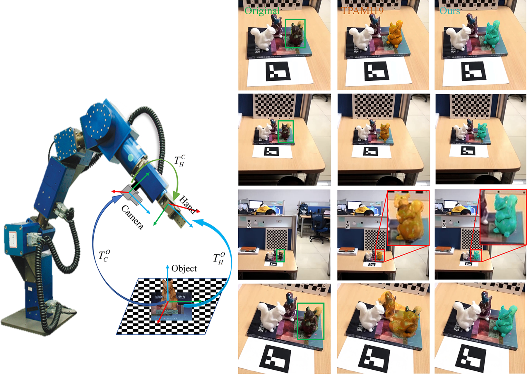
Monocular pose tracking of object with large-span scale change in robot manipulation. The large visual range variation between the camera and the object in detaching and approaching scenarios brings great challenges to robust pose tracking. Left: Accurate robot manipulator based on eye-in-hand monocular camera. Right: first column: input sample images of large-span scale change of the object caused by large visual range variation; second column: tracking results of the region-based method TPAMI19 17 ; third column: tracking results of the proposed method. The reprojected results show that the proposed method can accurately track the object within the large range of the scale change while TPAMI19 17 failed.
In the pose tracking research, RGB approaches mentioned above is usually known as monocular pose tracking methods. For monocular pose tracking methods, prior information about the object is usually exploited. Apart from its geometry information (e.g. CAD model), the object appearance information is also employed, including texture, templates, keypoints mapped on the object surface, and so on. 18 Specifically, depending on the difference of the image information used, existing monocular pose tracking methods can be classified into five major categories 19 : direct methods, feature-based methods, edge-based methods, region-based methods, and deep learning based methods.
In direct methods, the photometric consistency of consecutive frames is the basis, through which direct image alignment is operated to estimate the object’s pose variant. 20 Thus, such methods are sensitive to dynamic light, noise, and so on. For feature-based methods, sufficient and distinct texture is requisite to provide robust feature points, which makes such methods uncapable of tracking texture-less objects. Edge-based methods 21,22 generally sample a set of control points along the edge of the reprojected 3D model. Then, for each sampled point, the correspondence is determined by 1D searching along the normal direction. The pose is tracked by minimizing the distance between the sampled edge points and their corresponding points. This kind of methods can easily fall into local minima and easily fail in tracking heterogeneous objects. 18,21,22 Recently, region-based pose tracking methods 17,23,24 have gained increasing popularity and achieved state-of-the-art performances. Region-based methods unite pose estimation and image segmentation with the 3D model simultaneously. The object pose is estimated by iteratively optimizing the pose parameters that minimize the segmentation energy. These methods perform well when handling interferences, such as cluttered background, dynamic lighting, motion blurs, and defocus. Deep learning-based pose tracking methods normally track the object’s pose after the pattern of tracking-by-detection. 10 –16 These methods face the drawback of instability and inaccuracy in continuously tracking the object. More recently, temporal information is introduced in deep learning-based methods for 3D object pose tracking, such as DeepIM, 25 which greatly boosted the accuracy and robustness. Nevertheless, the preparation of a large-scale training data and the generalization ability can be a nuisance to practical use. Traditional methods use features with clear meanings and do not need training data, which is easy to be implemented in real application.
However, traditional region-based pose tracking methods have trouble in adapting to the scene with large visual range change. In many robot manipulation processes, the robotic hand usually needs to adjust the position and the pose for several times to meet the best manipulating conditions. Accordingly, the hand-eye camera approaches and detaches the object, back and forth. The distance variation between the camera and the object can be large, which in turn causes large-span change of the object scale in the image sequences captured by the hand-eye camera, as shown in Figure 1. To the best of our knowledge, the local region-based method proposed in the study by Tjaden et al. 17 is the most representative and advanced method in monocular pose tracking. However, as indicated in Figure 1, significant performance degradation is revealed when running the method 17 in practical terms, where the size of the object changes considerably caused by the drastic distance variation. From the perspective of object segmentation, object scale change often results in inconsistent statical property for both foreground regions and background regions when applying a fixed local region radius.
Fixed local region size restricts the performance of the existing region-based pose tracker for the large-span object scale change scenarios. Inspired by Lankton et al., 26 we believe that the region circle radius should be adjusted adaptively according to the size of the target. This article focuses on realizing stable and precise 6D pose tracking in the large visual range variation scenarios, which causes large-span object scale change. To tackle this problem, we proposed a scale-adaptive region-based monocular pose tracking method. In this article, we firstly analyze the impact of the object scale on the convergence performance of the local region-based pose tracker and study the local region size selection to optimize the converging power of the pose tracker. Based on the analysis, the radius dynamic modulation strategy based on object scale is proposed and merged into the traditional localized region-based tracker. The proposed method adjusts local region size according to the scale of the object projection, severely affected by the distance variation between the camera and the object. For the evaluation section, synthetic image sequences to simulate the manipulator motion in grasping tasks are rendered. Also, real image sequences are captured to validate the effectiveness of the proposed method. Experiment results on synthetic and real image sequences indicate that the proposed method achieves better tracking performance over the traditional local region-based tracking method in manipulator operation scenarios which involve large visual range variation.
The rest of the article is organized as follows. The second section describes the related works. In the third section, we analyze the relation between the local region radius selection and object scale. Details of the proposed method are presented in the fourth section. In the fifth section, experiments are carried out to demonstrate the effectiveness of the propose method. This article comes to a conclusion in the sixth section.
Related works
There is a lot of relevant research work in monocular pose tracking. As mentioned above, the region-based methods have achieved optimal performance so far. However, it cannot handle sizeable visual range variation cases well. This article proposed a novel scale-adaptive region-based method for robust monocular 3D object pose tracking for large visual range variation in robotic manipulation. The most relevant works are summarized in this section.
Region-based monocular pose tracking
With the known 3D model of the object, the object’s silhouette can be fully defined by its pose, segmenting the image into the foreground and the background. In region-based methods, the 3D pose tracking problem is considered as a joint problem of 2D segmentation and 3D pose estimation. And the object is tracked by seeking the pose with the optimal segmentation between the foreground (i.e. the object) and the background. Previous region-based methods 17,23,24,27,28 generally represent the contours using level set functions and the energy function is defined based on the likelihood of the pixel-wise property under a given model. The pose parameters are calculated by maximizing the energy function using iterative closest points. However, the complexity of segmentation and iterative optimization make it impossible for real-time implementation.
Prisacariu et al. 28 accelerated the projection of a 3D model using the GPGPU and introduced a pixel-wise posterior foreground and background membership approach to define the energy function. They proposed the first real-time region-based pose tracking method named PWP3D. Several successive works have been proposed recently based upon the general framework of PWP3D. The two main potential improvements of the original method are the pose optimization scheme and the simple segmentation model. For pose optimization, PWP3D adopted the simple first-order gradient descent method with four different fixed step sizes and a fixed number of iterations. For the segmentation model, the global model used in PWP3D is prone to fail in complex scenes that contain heterogeneous objects or a cluttered background. In order to better capture the spatial variation in statistical properties, Hexner et al. 27 proposed a local appearance model by applying from the idea of local active contours 26 . Similar to the study by Hexner and Hagege 27 , Tjaden et al. 24 also utilized the local region model. However, in the studies of Tjaden et al. 23,24 , for better segmentation quality, local regions were used to compute the average posterior probability instead of the average energy in the study by Hexner and Hagege 27 . Furthermore, Tjaden et al. 17,24 used the Gauss-Newton optimization approach for acceleration. The Hessian matrix is approximated from the first-order derivatives based on linearized twist parameterization. 24,17 The Gauss-Newton optimization scheme also significantly improve the accuracy and the robustness toward pose variations.
The existing local region-based methods perform well in scenarios where the object scale change in a small range. When handling robot manipulation tasks as mentioned in the first section, the large-span object scale change in the image sequence makes the existing local region-based method hard to adapt, in which a fixed local region size is applied.
Localized region-based segmentation
As mentioned above, region-based methods perform pose estimation and image segmentation with the 3D model simultaneously. The image segmentation and pose estimation performance are strongly bonded together, which both depend on the posterior probability functions deducted from the appearance models. In image segmentation, region-based methods were researched intensively earlier, in which studies on localized region-based techniques can be instructive for this article.
In order to improve segmentation result, the global appearance model is divided into multiple subregions, that is, localized region models. To localize segmentation, different ideas has been proposed in the past in various situations. Rosenhahn et al. 29 introduced the varying local Gaussian probabilities are to model the regions. For each pixel, a small window was defined to estimate the mean and standard deviation. Schmaltz et al. 30,31 focus on the articulated target with free-form surface, which consists of rigid parts interconnected by predefined joints. Each rigid part is considered separately. For the appearance model of a rigid part, the background is separated into multiple subregions and modeled with mixture models. The background is assumed static or slowly changing. Two algorithms are proposed in their works to segment the background. The first is K Means, which requires knowing the model order. And the other is a level set algorithm for optimizing the number of the regions. With the localized region models assigned to different parts, the segmentation performance is greatly improved. However, the correct model order is hard to select for the background segmentation.
Lankton et al. 26 proposed a framework to locally reformulate the region-based segmentation energy. Local region appearance models are used to provide image statistics for evolving the active contour. A point set is sampled along the contour. For each sampled point, a local region is attached, which is also split into the interior part and the exterior part by the contour. For each local region, a local segmentation energy measuring the difference between the interior and the exterior is then defined. The sampled points independently extend in the direction maximizing the segmentation. Through this approach, the spatial variation in the foreground and in the background are both addressed. Different from Rosenhahn et al., 29 in which localized Gaussian distributions are predefined, Lankton and Tannenbaum 26 model the probability functions without any assumptions.
The local size selection has been mentioned and studied in region-based segmentation. Automatic scale-dependent region size selection is also proposed by many authors. Their results are instructive for our work, but some differences exist. In the active contour segmentation problem, each center point can be moved independently; however, for localized region-based pose tracking, the regional center point is constrained by the given 3D model and the pose, which is more complicated.
Local region size selection based on object size
As analyzed before, traditional region-based pose tracking cannot adapt to the large scale change of the object, due to exploiting a fixed local region size. The local region size selection should depend on the object scale. This section researches in depth on the effect of the local region size on pose tracking. Then the relationship between local region size and object size is studied. The motivation and experimental settings are introduced in the sections “Motivation” and “Synthetic analysis settings.” In the section “Impact of local region radius size on the convergence performance of the pose tracker,” we discuss about how the object scale influences the local region size selection. And the section “Parameterization of local region radius selection upon object scale” describes the relationship modelling modeling of the region radius selection upon object scale via quantitative analysis.
Motivation
For the selection of local region size which is noted as radius for circular regions, Lankton et al. 26 discussed it in detail on contour segmentation problem. Their research indicates that the region circle radius should be chosen according to the size of the object. As shown in Figure 2, targets in small scale need smaller radius to accurately depict the difference between inner and outer regions to ensure the segmentation accuracy. However, for objects of larger size, an appropriate radius of larger region is preferred. Existing local region-based pose tracking methods set the local region size as a fixed value, which is usually a tradeoff between accuracy and robustness for the whole process. However, when encountering the drastic visual range variation, local regions with a fixed size are very likely to cause degradation of the tracking performance (as shown in Figure 1). As the visual range increases, the target size in the image decreases. The region size becomes relatively bigger, and the local regions become more correlated, with less variation between regions, thus leaning toward global region statistics, which makes the tracker less capable of tracking heterogeneous object, as shown in Figure 2. Therefore, fixed region circle for different object scale is inappropriate. And this article intends to propose a scale adaptive pose tracking method.

Local region radius selection for object with large-span scale change. (Local regions of different radiuses are drawn along the contour of the object. Green circle: radius = 80 pixels; yellow circle: radius = 40 pixels; blue circle: radius = 20 pixels. The image sizes for both images are 800 × 800 pixels.).
Synthetic analysis settings
To explore how object scale affect the convergence performance of the local region-based pose tracker in real application, synthetic experiments are carried out. To be noted, the local region-based pose tracker to be tested in this section is described in detail in the fourth section. Firstly, we choose five textured objects from the RBOT dataset 17 and use a powerful physical based rendering engine blender to render the objects in a real planar scenario. As shown in Figure 3, these selected objects include simple ones and complex ones in terms of the 3D shape, and also homogeneous ones and heterogeneous ones in terms of textures. In this article, we only consider to differentiate the objects according to the distinctiveness of the objects compared to the same background, as shown in Figure 3. By changing the distance between the virtual camera and the target, we can obtain sequences of synthetic frames, in which the size of the target simply varies with the changing visual range.

Semisynthetic frames of five objects using blender (from left to right: squirrel, ape, camera, duck, and phone; the objects are all selected from RBOT dataset). 17
With the rendered frame sequences of object scale change, we test the performance of the pose tracker by initializing the tracker with erroneous poses to validate whether the tracker can successfully converge or not. Through testing different local radiuses, the success rates for frames of different object scale are counted. In this article, we classify the initial pose errors into three types: the rotation error, the in-plane translation error, and the radial translation error (refer to Figure 4). Specifically, the rotation error represents the angle error when object rotates. The in-plane translation error and the radial translation error represent the translation errors in X-Y plane and Z direction in camera coordinate, respectively. In real robot manipulation tasks, the servo system usually guarantees that the object locates near the center of the image captured by the hand-eye camera. The in-plane translation pose error between adjacent frames is greatly reduced. Therefore, for analysis in the following sections, converging tests of the pose tracker on the rotation pose errors and the radial translation errors are mainly focused on.

Illustration of the imposed initial pose errors of three types (left: rotation error; middle: in-plane translation error; right:radial translation error; the green contours represent the correct pose).
For quantitative analysis, the target size in the image is measured by the length of the short side of its minimum bounding rectangle in this article, as shown in Figure 5. We sampled few frames of different object scale ranging from 40 pixels to 200 pixels for analysis. The examples of sampled squirrel frames and the scale change curve with respect to the visual distance are shown in Figure 5. In each experiment, the local region-based algorithm, which is described in the fourth section, is tested with different local region radiuses after initializing the object’s pose to a random initial error. Considering that the 3D sizes of the selected objects are ranging from 100 mm to 200 mm, tracking success is defined as a final rotational error of not more than 5° in rotation and 10 mm in translation (less than 10% object 3D sizes). Limited by space, this section mainly presents the detailed intermediate analysis processes of squirrel as an example. The other four objects are analyzed using the same manner.

The different object scale of semisynthetic frames of squirrel and the scale change curve with respect to the visual distance. (Note: the object scale is denoted by the short side of minimum bounding rectangle, and the squirrel 3D size is 111 mm × 194 mm × 181 mm.)
Impact of local region radius size on the convergence performance of the pose tracker
In this section, we test the convergence performance of the pose tracker with different radius sizes for each object scale. The experiments are carried out on the rotation pose errors and the radial translation pose errors, respectively. For each type of pose errors, we set different error levels. For example, the rotation errors are generated with 5° to 50° with a step of 5 degrees, around the ground truth. For the radial translation errors, we set ±10 mm to ±50 mm with a step of 10 mm, which is approximately 10% radial size of the selected models. For each error level, we generate 200 random poses for testing. The pose tracking success rates are presented in Figure 6.
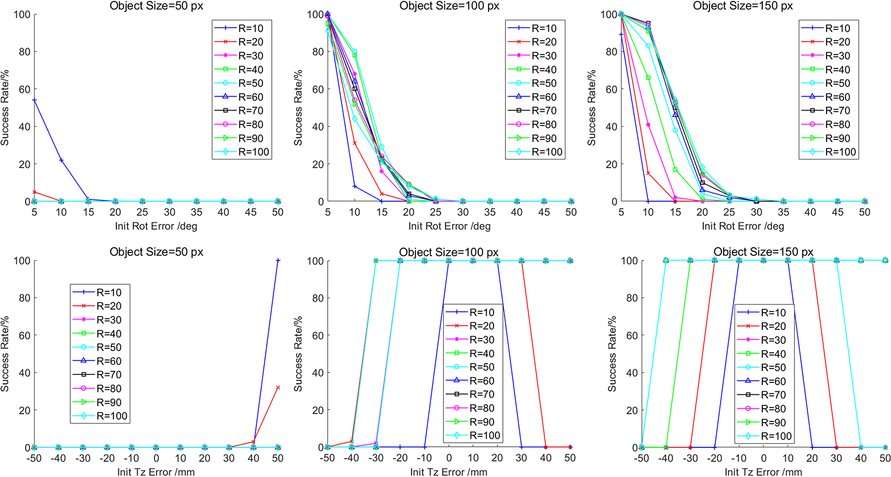
Overall convergence success rates of estimating the correct pose of three selected object scales for squirrel. (First row: success rates under rotation errors. Second row: success rates under radial translation errors.)
Figure 6 shows the overall convergence success rates of estimating the correct pose of three selected object scales for squirrel, in which, the convergence performance for each radius curve can be partially indicated by the area under curve. We can discover that the probability of converging success rate for higher level error, that is, the error tolerance, increases along with the object size. Also, as the object size grows, the performance of different radius changes. The reason is that when then object size becomes bigger, more details show up, which are beneficial for the pose tracker to converge to the correct pose whichever radius is applied. In general, bigger object size in the image offers more detailed information, making it easier for the pose tracker to converge. Different object scales authentically affect the region radius selection.
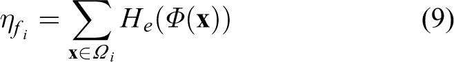
In order to compare the convergence performance of each radius curve for every object size, the performance is quantized through weighted success rates as performance score
Error level definition for different pose error types.


where l is the error level of the initial pose,
For each object size, we aim to find the optimal radius for the convergence performance of the pose tracker. We consider the object sizes in different frames are separated. For the convenience of comparing the relative performance within certain object scale, the performance scores of every testing radius for each object size are normalized. Based on equation (1), we compute the relative normalized performance value as

where,

The normalized performance score graphs of testing radiuses for different object sizes of squirrel. Left: for initial rotation errors; right: for initial Tz errors. The value ranging from 0 to 1 in the color bar represents the normalized performance score under each object size. Warmer color stands for better performance.
To be more specific, in Figure 7, the values ranging from 0 to 1 in the color bar for heatmaps corresponds to the normalized performance score under each object size. Warmer color stands for better performance. For both of the rotation pose errors and the radial translation errors, as the object scale enlarges, the optimal radius increases as well. From the analysis above, in order to stimulate the optimal convergence ability for each frame, the local region radius selection should be adjusted according to the object size.
Parameterization of local region radius selection upon object scale
All the five objects are analyzed using the same manner. In order to clearly present the relation between the local region radius selection along with the change of the object scale as well as to better cover the variational trend, radiuses which score the top 3 on the convergence performance for each object size are selected and plotted into curves for parameterization. In Figure 8, the Top3 Radius-Object Size relation curves in terms of different types pose errors are drawn, respectively. The results for the five objects with different shapes, textures, and distinctiveness are demonstrated, for the purpose of summarizing a rather general pattern.

The Top3 Radius-Object Size relation curves of the five objects. For each row, the left graph shows the analyzed object, the middle and the right graphs are the statical results for initial rotation error and for initial radial translation error, respectively. The bold black curves are the sigmoid fitting curves for each graph using equation (3).
The relation between the radius of optimal performance and the object size exhibits nonlinear characteristics. According to the curves shown in Figure 8, the radius-scale relation, in terms of rotation errors, behaves more regularly, that the optimal radius is positively correlated to the object scale in certain range. As for the radial errors, the variational curves for squirrel, ape, and phone are similar to that of rotation errors, however, the curves for duck and phone behave irregularly. This is because the distinctiveness of duck and phone reduces the effect of radius selection on the radial translation error convergence.
As shown in Figure 8, we use the sigmoid function to fit the curves to cover the variational trend of the optimal radius upon object scale. The fitting curves are drawn in bold black lines in Figure 8, which nicely depict the characteristics of the distributional trend. Therefore, to model the relation between the local region radius selection and the object scale, we establish the following rough parameterized expression as,

where,
The approximate fitting curves are shown in Figure 9. The parameters in Figure 9 are only theoretical fitting parameters for reference. In practical application, the parameters should be adjusted referring to the appearance character of the object. The slope coefficient a and the horizontal offset b should be adjusted according to the shape complexity and the distinctiveness of the object.

The approximate sigmoid fitting curves (the indexing note shows the typical parameters after fitting, in which,
Scale-adaptive localized region-based monocular pose tracking
To tackle the problem of pose tracking of the object with large-span scale change, this article proposes a novel scale-adaptive local region-based monocular pose tracking method. In this section, we first describe the problem formulation and notation in pose tracking. Then the proposed scale-adaptive localized region-based pose tracking model is introduced in detail.
Problem formulation and notation
In the pose tracking problem, we assume an initial object pose (the pose of the first frame) is given and try to estimate the 6-DOF pose of the object in the subsequent video frames. The diagram of monocular pose tracking is shown in Figure 10. The 3D model used in this article is represented by a dense surface model (triangle mesh) that consists of 3D points

Localized region-based monocular pose tracking. Left: the diagram of monocular pose tracking.

The camera is pre-calibrated and its intrinsic parameters are assumed fixed. The intrinsic matrix

After removing non-linear distortion, the input images are considered undistorted. The perspective projection of a 3D vertex point to a 2D image point can be described as

where
Scale-adaptive localized region-based pose tracking model
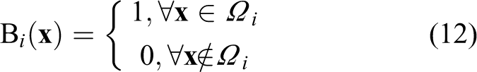
This article proposes a novel scale-adaptive localized region-based tracking model. For local region-based methods, the object in the image is represented by a level-set embedding function (or the signed distance function)
For each local region, an individual color model could be calculated, and the local pixel-wise posteriors are computed as:


where,
The next step is to fuse all the local statistical models and formulate the overall energy function. Similar to the studies of Tjaden et al., 17,24 we choose to compute the average posteriors from all local histograms that the pixels belong to, instead of computing the average energy over all local regions. The average posterior maps are calculated as:


where,
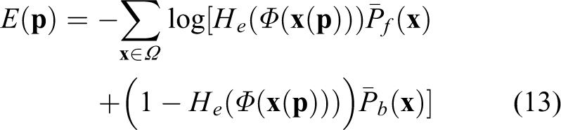
Then the localized region-based energy function used for pose tracking can be formulated as:
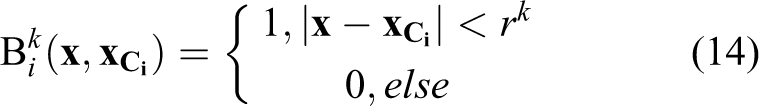
As analyzed in the third section, in order to adapt the scale change caused by visual range variation, we consider update the region radius along with pose parameters according to its projected contour size. We assume that the object scale between adjacent frames keeps the same. The minimum bounding rectangle of the projected contour of the previous frame is detected first, the shorter side of which is used to represent the object size, as shown in the left graph in Figure 11. Based on the analysis and parameterization of the radius selection, the region radius applied in the current frame is calculated.

Local region radius update. (The red contour in the right graph represents the pose in the previous frame. We use the shorter side of minimum bounding rectangle of the projected contour to represent the object size. Object size detected in the previous frame k-1 is referred for the radius selection in the current frame k.).
To update the region circle radius, we replace

where
Experimental evaluation
To validate the performance of the proposed method, experiments on synthetic and real image sequences are conducted. We compared our method with the representative region-based method TPAMI19 17 and edge-based methods (VC15 22 , TCSVT21 18 ). For all the methods to be compared, we adopt the parameters suggested by the authors directly. All experiments are performed on a laptop equipped with an AMD Core R7-4800 H octa-core@ 2.9 GHz, a NVIDIA Geforce GTX1650 GPU, and 16 GB RAM. The GPU was only used for rendering. Our method is implemented in C++. The images for the rendered sequences and the real sequences are all with the size of 800 × 800 pixels. The proposed method runs around 25–30 Hz in average, which indicates that the proposed method is suitable for real-time application.
Evaluation on the synthetic image sequences
Synthetic image sequences are rendered to simulate monocular image sequence during the grasping process of the robotic hand. Similar to the third section, this article choses ape, camera, duck, squirrel, and phone from the RBOT dataset and generates new synthetic image sequences for each object using blender. Each sequence contains 260 frames. During rendering, the trajectory of the virtual camera is designed to imitate the grasping hand motion path for reseeking the grasping keypoints on the objects. The simulated camera trajectory contains the typical detaching and approaching movement, surrounding movement, and axial rotating movement, as shown in Figure 12. Considering that the servo of robotic arm keeps the grasping hand toward the objects, the objects are located near the center of the view along the image sequences.

The virtual camera trajectory in rendering synthetic image sequences. (The visual distance between the camera and the object ranges from 400 mm to 1000 mm.)
For qualitative evaluation, we compare the proposed method with the studies of Tjaden et al., Sun et al., and Wang et al. 17,18,22 Figure 13 shows the sampled reprojected tracking results on the synthetic image sequence of phone. It can be seen that the object size of Phone varies over a wide range due to the variation of the camera–object distance. The object size of phone ranges from 50 pixel to 200 pixel, as shown in Figure 14. The sequence also contains rapid rotational change when the camera rotates axially along with the grasping hand, which brings more challenges for robust pose tracking. From the reprojected results, we find that edge-based methods 18,22 tend to fail in tracking the pose when the object scale starts to shrink. TPAMI19 17 keeps tracking successfully until the object scale decreases to the minimum and starts to fail when the object rotates in its smallest scale. The proposed scale-adaptive region-based method successfully tracks the object’s pose in the whole sequence. The scale-adaptive mechanism proposed in this article adjusts the local region size according to the object scale dynamically, as shown in Figure 14.


The local region radius update based on object size in synthetic image sequences of phone.
For quantitative evaluation, we adopt the pose tracking error metric used in the studies by Tjaden et al. and Pauwels et al.
17,32
. For each frame, we compute the translation error

where
We compare our method with the representative region-based method 17 and edge-based methods. 18,22 Specifically, to test the fixed local region-based method in a more comprehensive manner, we set the local region radius parameter in TPAMI19 17 from 10 pixels to 100 pixels, with other parameters remaining the same. The tracking success rates are presented in Table 2.
As indicated in Table 2, the proposed method achieves the best overall performance among all the testing pose tracking methods. The overall performance of the compared edge-based methods 18,22 behaves inferior to the region-based methods, because the edge-based methods only utilize the sparse information of 1D search lines or the gradients. Whereas TCSVT21 18 achieves the best success rate far beyond that of other testing methods in tracking Duck. The reason is twofold: Firstly, the 2D silhouette of duck exhibits more rounded. Along the contour of the rounded homogenous object (duck), the foreground-background distribution difference in the local regions is hard to capture from frame to frame for region-based method, causing the low tracking accuracy for region-based method. Although we adaptively adjust the region radius, the performance improvement is limited. Secondly, the texture-less duck provides strong gradient correspondences for TCSVT21 18 to detect then to accurately track the poses. In the synthetic image sequence, the simulated camera motion causes drastic scale change and sharp rotational change of the object, which makes it hard for all the compared methods 17,18,22 to accurately track the poses along the whole process. The proposed method achieves highest tracking success rates in ape, camera, squirrel, and phone. For the compared region-based method TPAMI19 17 with fixed local region size, it performs differently when implemented with different region size. However, under the condition that the object exhibits a large scale change in the image sequence, a fixed radius is not capable of getting the optimal result. For the performance improvement, the local region radius should be varied along with the object scale change.

The proposed method adopts the scale-adaptive strategy to dynamically change local region radius based on the object scale, aiming at releasing the maximum convergence power for each frame. The synthetic image sequences experiment results demonstrated the effectiveness of the proposed method.
Evaluation on the real image sequence
We also evaluate the proposed method on real image sequences. The real image sequences are captured through a RGB industrial camera assisted by a stabilizer to simulate the hand-eye camera of the robotic hand. During capturing, we move the camera to depart the squirrels to a long visual range at the beginning. Then we hold the camera to return to the object from a slightly different angle. The squirrels used in the experiment are 3D-printed and re-painted from a cad model in RBOT dataset. The first image sequence used in our experiments contains 842 frames in total, with the size of 800 × 800 pixels. The ground-truth poses of the object are obtained by using a 2D marker provided by the ArUco library. 2 We also compared our method with the studies of Tjaden et al., Sun et al., and Wang et al. 17,18,22 For the method to be compared, we adopt the parameters suggested by the authors directly. In the image sequence, three squirrels are captured, as can be seen in Figure 15. Since the right squirrel is unpainted and exhibits rather distinctive in the frame, the proposed method and compared methods can successfully and accurately track it. And the middle squirrel is severely occluded, all the testing methods are badly degraded. We only test the methods tracking the pose of the right squirrel in the frame sequence. This experiment is carried out to verify the continuous pose tracking ability of the proposed method in real applications with large-span scale variation.

Pose tracking results of the compared methods and the proposed method on the real image sequence. Top: the sampled reprojected results: first row shows the input images; second to fifth rows are the pose tracking results of VC15, 22 TCSVT21, 18 TPAMI19, 17 and ours, respectively. Bottom: curves of the tracked 6D poses. (The pose ground truth is labeled in full lines with red triangles; the results of the proposed method are labeled in dashed lines with green squares.)
As shown in Figure 15, the squirrel with dark heterogeneous texture located on the right side is the target to be tracked. After being initialized, our method can track the object accurately from the start to the end, while the studies of Tjaden et al., Sun et al., and Wang et al. 17,18,22 gradually fail as the object scale becomes increasing small. Since VC15 22 fails at the beginning of the sequence, we only discuss about the results of the studies of Tjaden et al. and Wang et al. 18,22 . From the pose curves shown in Figure 15, we can identify that the tracking failure of the studies of Sun et al. and Wang et al. 18,22 starts from around the 300th frame. Form around the 300th frame to the 400th frame, the radial movement of the camera becomes severe, which causes the drastic object scale change, mainly leading to the estimated rotation and translation Z parameters inaccuracy. When the object scale recovers to the original size, the pose errors tracked by the studies of Sun et al. and Wang et al. 18,22 accumulate gradually, leading to the final tracking failure.
To further evaluate the practical performance on real application, other real image sequences are captured to stimulate the robotic grasping process under complex scene, in which different objects are randomly placed together. For the image sequences under complex scene, a similar experimental configuration is applied above. A sample of the image sequence is presented in Figure 16. Apart from the large visual range change, this sequence contains more complex real situations such as drastic rotation change, occlusion, and so on. The second real image sequence in our experiments contains 623 frames in total, with the size of 800 × 800 pixels. The ground-truth poses of the objects are obtained using a 2D ArUco marker board.

Pose tracking results under complex scene. Top: the sampled reprojected results: first column shows the input images; second to fourth columns are the pose tracking results of TCSVT21, 18 TPAMI19, 17 and ours, respectively. Bottom: curves of the tracked 6D poses. (The pose ground truth is labeled in full lines with red triangles; the results of the proposed method are labeled in dashed lines with green squares.)
All the testing methods are initialized using the pose ground truth of the targeted squirrel. Figure 16 shows the pose tracking results of the second real image sequence. As shown in the pose curves in Figure 16, our method is still able to track the object accurately in the whole process. VC15 22 fails at the beginning of the sequence, TCSVT21 18 and TPAMI19 17 start to lose tracking the object at around 250th frame, when the object is at a relative small scale in the sequence, and the camera is at a sharp rotating motion. In Figure 16, we separately select the 252th frame and exhibit the reprojected tracking results of the testing methods. From the zoom window, we can find that the motion blur effect and occlusion exist in the input image, due to the camera motion and complex scene. The reprojected results show that our method is still able to adapt to these situations while the compared methods easily fail under this complex scene.
Different from the synthetic image sequences, the real-world image sequences contain more disturbances, such as defocused noise, motion blur, and occlusion, and so on. Also, in the real-world image sequence, in-plane translation pose variation is involved. Still, our method is capable of accurately tracking the pose in the whole process, which again proves the effectiveness and the strong adaptation capability of the proposed method.
Runtime performance
The runtime performance of our method and the compared methods are presented in Table 3.Compared with TPAMI19 17 , the proposed method has one more step of parameter adaptive adjustment, which updates the local region radius parameter in the tracker executed in each frame by detecting the size of the object in the previous frame according to the parameter adjustment strategy analyzed in the section “Parameterization of local region radius selection upon object scale.” The size detection step is executed by directly finding the minimum bounding rectangle in the OpenGL rendering function. The adjustment of radius parameters barely affects the execution efficiency of tracker. Therefore, the extra time of the proposed method compared to TPAMI19 17 takes about 3–5 ms per frame. However, the improvement of the proposed method in tracking accuracy and robustness is impressive in terms of large-span visual range scenario, compared to other methods.
Runtime performance (per frame in ms).

Discussion
Although the capability of the propose method on both synthetic and real experiment is demonstrated, there are still some limitations.
The selection of local region size is related to multiple factors. This paper only considers the object scale, which is the main variant in robot manipulation tasks. Through experiments, we also find that shape complexity and the texture distinctiveness of the object should also be considered for the local radius modulation. For distinct homogenous object, the pose tracking performance is quite insensitive to the local region size selection.
The parametric model proposed in the section “Parameterization of local region radius selection upon object scale” is an approximate model for local radius modulation. For actual implementation, the parameter setting is highly based on experience. The slope coefficient and the horizontal offset should be adjusted according to the shape complexity and the distinctiveness of the object. The more complex the object shape is, the smaller slope coefficient and the larger horizontal offset should be. Similarly, lower distinctiveness also calls for smaller slope coefficient and larger horizontal offset to suppress the radius from growing too fast along with the object scale. This is because complex object shape and lower distinctiveness require the local regions to capture more variability between the foreground and the back-ground.
The scale-adaptive mechanism proposed in this article can also be referred to as a framework in dynamic parameter modulation of the searching field in edge-based methods for better adaption to object scale change.
Conclusion
This article focuses on robust monocular pose tracking in robot manipulation with large-span scale change of the object for hand-eye camera. To handle the problem, the article proposed a novel scale-adaptive local region-based monocular pose tracking method. In this article, we firstly analyzed the impact of the object scale on the local region radius selection of the pose tracker. Based on the statical analysis, the scale-adaptive local region size updating strategy was developed. We applied the scale-adaptive mechanism to the conventional local region-based method to improve its tolerance upon large visual range variation. The proposed method adjusts local region size according to the scale of the object projection which is severely affected by the visual range variation between the camera and the object. Both synthetic and real-world experiment results show that the proposed method can achieve robust tracking in real-time in terms of drastic visual range variation.
Footnotes
Data availability
Data underlying the results presented in this article are not publicly available at this time but may be obtained from the authors upon reasonable request.
Declaration of conflicting interests
The author(s) declared no potential conflicts of interest with respect to the research, authorship, and/or publication of this article.
Funding
The author(s) disclosed receipt of the following financial support for the research, authorship, and/or publication of this article: This study was funded by Postgraduate Scientific Research Innovation Project of Hunan Province (CX20200024, CX20200025, CX20200088); Hunan Provincial Natural Science Foundation of China (2019JJ50732); and National Natural Science Foundation of China (62003357).