
Abstract
Objective
To quantify dynamic gutter phenomena and endograft deformations during double chimney thoracic endovascular aortic repair (ch-TEVAR) in a physiological model of the thoracic aorta subjected to pulsatile haemodynamic conditions.
Methods
Two in vitro procedures revascularizing the brachiocephalic trunk and left common carotid artery were performed representing both balloon-expandable (BE, Ankura-BeGraft) and self-expandable (SE, Ankura-Viabahn) double ch-TEVAR configurations. Retrospectively gated computed tomography (CT) was used to evaluate endograft behaviour. Device interactions were characterised according to gutter volume, gutter surface deviation, and endograft deformation (D-ratio) at end-diastolic and peak-systolic aortic pressure.
Results
Use of BE chimney grafts resulted in three times total gutter volume compared to SE chimney grafts. Gutter volumes were observed to vary dynamically between the end-diastolic and peak-systolic phases of the cardiac cycle, with the most substantial change associated with the BE configuration. Chimney graft deformations were dependent on device type, with SE devices exhibiting up to twice the deformation as BE devices. When adjacent, SE chimney grafts were observed to support each other, and thus tended towards a more consistently circular shape.
Conclusion
Gutter and chimney graft behaviour were dependent on device type, and exhibited both spatial and temporal variability. This study emphasises notable differences between BE and SE double ch-TEVAR configurations which should be considered when evaluating risk of endoleak. The findings reported here also support the use of gated CT to better identify device-related complications with ch-TEVAR, and can be used in the design of next generation devices.
Introduction
Diseases of the aortic arch (e.g., aneurysm, dissection) are life-threatening conditions requiring intervention in patients who present with a high likelihood of rupture. Traditionally, these diseases have been treated via an open surgical approach. Such procedures, however, are associated with significant risk thereby precluding patients who are unfit for invasive repair.1–3 In an effort to manage these patients, minimally invasive thoracic endovascular aortic repair (TEVAR) techniques, which are well established for diseases of the descending thoracic aorta, have been refined to address the complex biomechanical and morphological challenges of the proximal aorta. 4
In recent years, both fenestrated 5 and branched 6 TEVAR has been reported as potential treatment options. Unfortunately, the stent-graft devices employed in those procedures are typically patient-specific, and therefore costly with lengthy manufacturing times, where patients remain at risk of rupture. The so-called chimney technique (ch-TEVAR) provides an off-the-shelf solution.
Originally reported by Greenberg 7 and Criado 8 as a ‘bail-out’ procedure, this approach employs the use of standard endografts deployed in a parallel fashion. Specifically, chimney stent-grafts (CGs) are placed in the supra-aortic branch vessels, sized with sufficient length to extend proximally into the ascending aorta/arch, and run parallel to the main endograft. The intended result is an aortic seal zone excluding the diseased aorta whilst maintaining branch vessel perfusion. Recent registries 9 and single-centre studies10–12 reporting on technical success and midterm outcomes demonstrate the utility of ch-TEVAR in treating high-risk patients, particularly in emergent settings. 13
Despite its feasibility, complications such as endoleak and CG compression persist. Regarding endoleak in ch-TEVAR, this phenomenon is predominantly associated with the formation of so-called ‘gutters’: channels between the aortic wall and (non-conforming) endografts, through which blood continues to flow, compromising the aortic seal. Conversely, CG compression stems from device deployment next to the main endograft, potentially leading to compromised CG patency. These two complications are particularly relevant in the case of double ch-TEVAR configurations, whereby two CGs are deployed across the aortic arch leading to increasingly complex device-device and device-artery interactions.
Recent benchtop studies have reported on the behaviour of endografts when used to treat challenging abdominal aortic aneurysms (ch-EVAR).14–16 However, to date, no experimental studies of ch-TEVAR have been reported in the literature. As such, the purpose of this investigation was to: (1) establish an in vitro vascular model subjected to pulsatile flow, (2) perform representative double ch-TEVAR procedures using both balloon-expandable (BE) and self-expandable (SE) covered CGs, and (3) quantify gutter volume and endograft deformations at critical time points during the cardiac cycle using retrospectively gated computed tomography (CT). It was hypothesised that both device type and cardiac pulsatility would influence the geometric and dynamic behaviour of ch-TEVAR configurations.
Materials and methods
In vitro thoracic aortic model
An in vitro thoracic aortic model, based on a post-mortem vascular cast and manufactured from silicone, was obtained from Elastrat Sàrl (Geneva, Switzerland). The anatomy includes the full thoracic aorta, supra-aortic branch vessels, and the major coronary arteries. Fluid flow was accommodated via an inlet located at the posterior surface of the ascending aorta, approximately 20 mm distal to the sinotubular junction. Essential model geometry for performing in vitro ch-TEVAR is illustrated in Figure 1 with additional characterisation provided in Supplemental Material 1. The thoracic model was connected to a secondary abdominal aortic segment including iliofemoral arteries (United Biologics Inc., Santa Ana, CA, USA) to provide typical endovascular access. Thoracic aortic model geometry used for in vitro ch-TEVAR. Dimensions reported as mean inner vessel diameter at 120 ± 40 mmHg. (STJ) Sinotubular junction; (BT) brachiocephalic trunk; (LCCA) left common carotid artery; (LSA) left subclavian artery. Landing zones defined as per Ishimaru’s aortic arch map. Zone 0 defined as the midpoint between the STJ and Z1, as no additional anatomical landmarks (i.e., bifurcation of the pulmonary trunk) present. Notes: complex 3D aortic lumen curvature not depicted; (*) fluid flow inlet.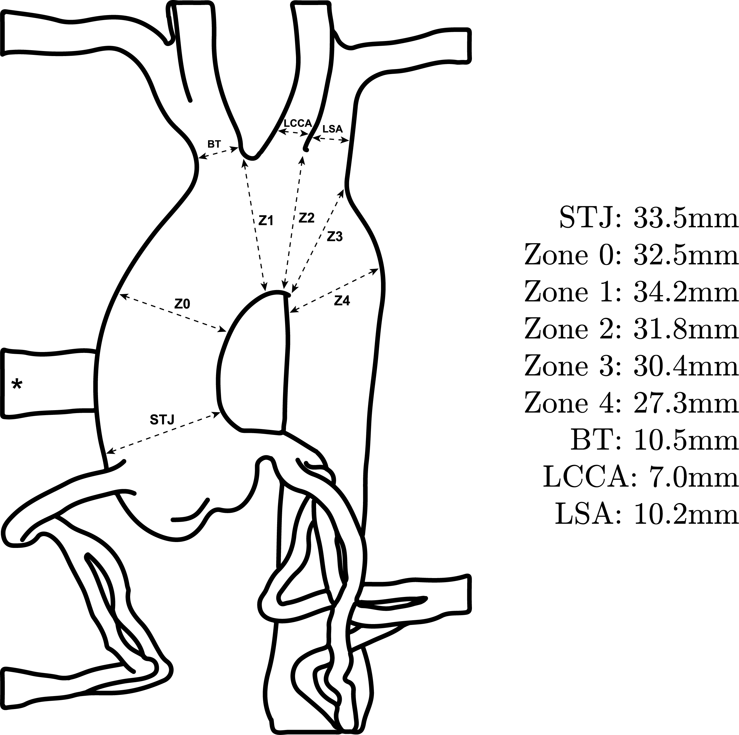
Haemodynamic circuit
A Portable Pulse Duplicator (Medical Implant Testing Lab Inc., Irvine, CA, USA) replicating left heart function was used to generate pulsatile haemodynamic conditions in the model. A sinusoidal pressure profile was applied, and a physiologic pressure range was tuned using a controller as well as systemic and peripheral resistances. Aggressive pulse pressure conditions matching typical pulsatile fatigue testing requirements (diastolic pressure of 80 mmHg and systolic pressure of 160 mmHg) was used, 17 with a heart rate of 70 beats per minute. A blood analogue consisting of 55% deionised water: 45% glycerol by weight 18 was circulated throughout the model, and its temperature controlled at approximately 37°C.
Image acquisition: Retrospectively gated CT
Imaging was performed using a 64 detector CT scanner (GE Healthcare, Chicago, IL, USA), with a standard retrospectively gated cardiac helical scan protocol (80-kV tube voltage, 100-mA tube current, 0.24:1 pitch, 40 mm detector coverage, 0.35 s rotation time) and a slice thickness of 0.625 mm. An idealised external ‘heart beat’ of 70 beats per minute was provided for the gated reconstructions.
In vitro ch-TEVAR procedures
Two double ch-TEVAR configurations were considered. Both employed a single 44 mmOD Ankura device (Lifetech Scientific Co. Ltd., Shenzhen, China), with an equivalent oversizing of 35%, as the main endograft. Either BE or SE chimney grafts were deployed into the brachiocephalic trunk (BT) and left common carotid artery (LCCA). Femoral access was obtained via a large-bore hemostatic valve. Supra-aortic branch access into the BT and LCCA was obtained using Tuohy Borst-type valves and standard introducer sheaths, approximating brachial access. The Ankura device was advanced over a 0.035” Lunderquist Extra-Stiff Wire Guide (Cook Medical, Bloomington, IN, USA) and deployed at a predefined landing zone. Branch vessels were then cannulated using either 0.018” or 0.035” access wires as appropriate.
In the first configuration, after main endograft deployment, BE 10 mmOD × 57 mm and 7 mmOD × 57 mm BeGraft covered stents (Bentley Innomed GmbH, Hechingen, Germany) were deployed into the BT and LCCA, respectively. Two devices, in an overlapping fashion, were deployed in each artery (four devices total). Following CG deployment, both the main endograft and CGs were simultaneously post-dilated. A compliant endograft remodelling balloon (Tri-Lobe, W.L. Gore & Associates Inc., Flagstaff, AZ, USA) was used to ensure the Ankura device adapted to the model aortic wall. Imaging was then performed as described above. Subsequently, the CGs were plastically deformed (crushed) and removed from the model using a retrieval snare (pfm medical, Cologne, Germany), leaving the main endograft in place.
In the second configuration, the supra-aortic vessels were re-cannulated in a similar fashion, with SE 11 mmOD × 5 cm and 8 mmOD × 10 cm SE Viabahn covered stents (W.L. Gore & Associates Inc., Flagstaff, AZ, USA) deployed into the BT and LCCA, respectively. SE devices were chosen to be one size larger than BE devices, in line with clinical practice at our institution. In this procedure, only a single device was deployed in each artery (i.e., two devices total). Again, both the Ankura and CGs were simultaneously post-dilated.
Of note, during cannulation of the supra-aortic vessels, exact positioning of the guidewires was not strictly controlled. That is, the guidewire paths running parallel to the Ankura device were dictated by ‘the path of least resistance’, as typically the case in vivo. As a result, CG deployment locations between BE and SE configurations differed, which affect the location and characteristics of subsequent gutters. Representative CT reconstructions of the in vitro double ch-TEVAR procedures are shown in Figure 2. IRB approval was not required for this study. Representative CT reconstructions of in vitro double chimney TEVAR: (A) Ankura-BeGraft and (B) Ankura-Viabahn configurations.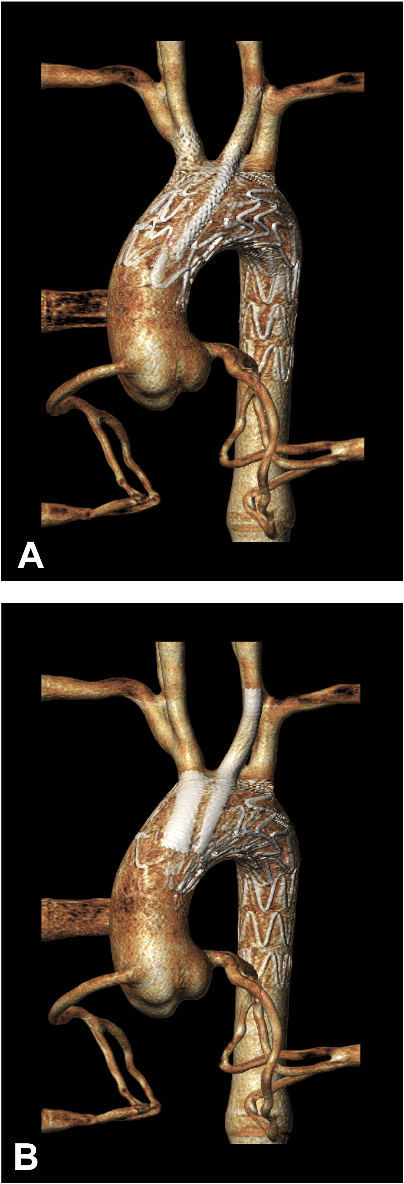
Evaluation of ch-TEVAR gutters
To assess the geometry and dynamic behaviour of ch-TEVAR gutters, the CT scan phases corresponding with minimum and maximum aortic pressures were identified. Each phase was subsequently analysed using a specialised workflow developed in Simpleware ScanIP (vN-2018.03, Synopsys Inc., Mountain View, CA, USA). Data was processed by means of a median filter to reduce noise. The aortic vessel wall, main endograft, and CG stent frames were then segmented and the axial slice at the level of the proximal edge of the main endograft covering was selected. Representative images highlighting the segmented aortic wall, main endograft, CGs, and quantified gutter areas of both experimental configurations are given in Figure 3. Gutter areas were quantified every 3–5 slices as appropriate, to a predefined axial slice at the level of the fourth endograft stent marker. Representative axial CT slices used for gutter evaluation in Simpleware ScanIP: (A) Ankura-BeGraft and (B) Ankura-Viabahn double chimney TEVAR configurations. (Red) Aortic wall; (blue) stent struts; (magenta) gutter areas; (green) segmentation contours.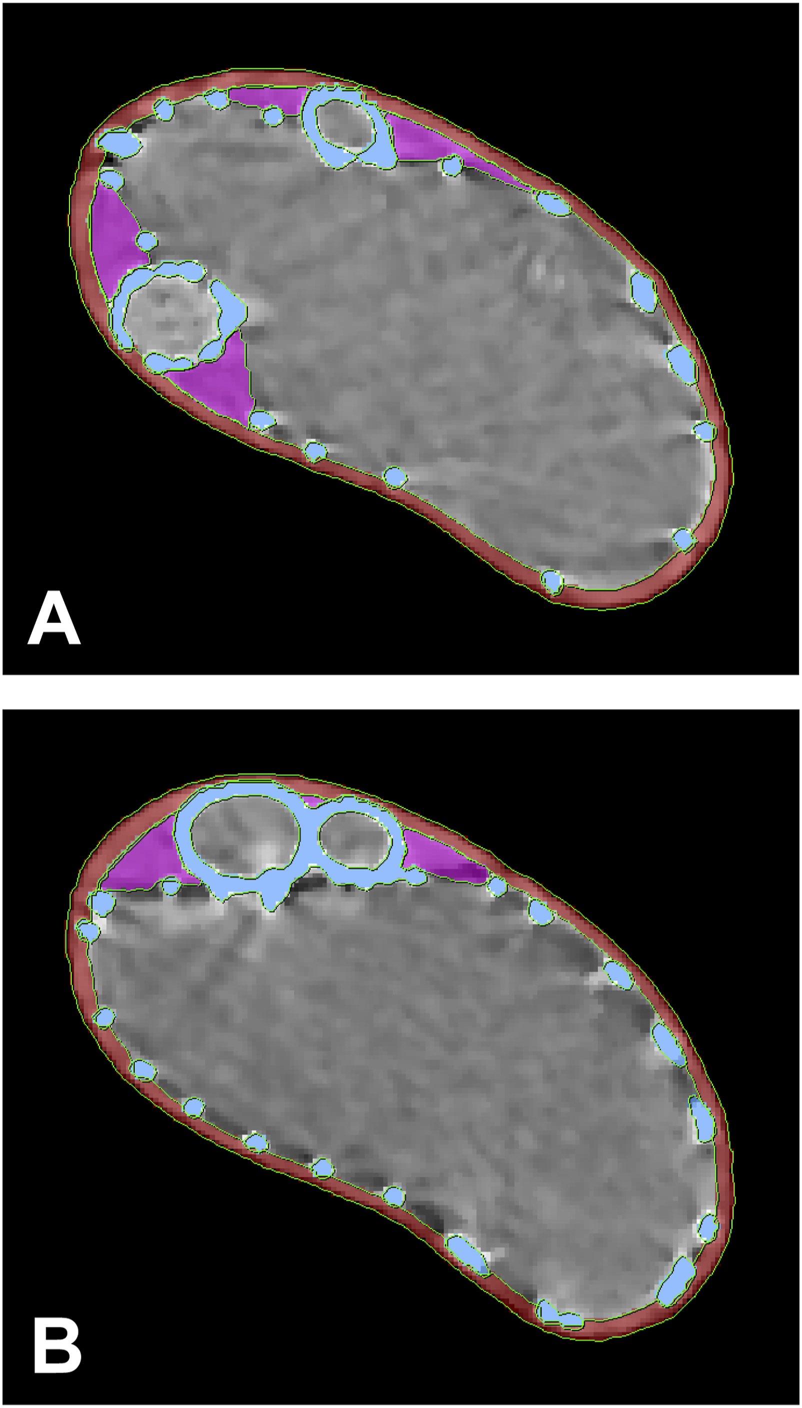
Using gutter cross-sections along the axial length, the gutter volume was constructed. The cross-sections were resliced along a centerline generated through the aortic lumen in order to achieve perpendicular slices. The voxel-based gutter was converted into a surface-based representation, from which gutter volume was calculated. The analysis was performed for two CT phases per experimental configuration, enabling quantification of dynamic behaviour of the gutter geometry during the cardiac cycle and comparison of gutter formation between different CG combinations.
In addition to quantifying gutter volumes, the change in gutter geometry was also assessed. Diastolic and systolic gutter surfaces were co-registered using a landmark-based registration algorithm. The effective gutter surface deviation was quantified by computing the distance from a grid of sampling points distributed across one gutter surface to the nearest point on the other gutter surface. 19 This analysis was performed as a means to evaluate the apparent geometric variation of gutters between minimum and maximum aortic pressures.
Evaluation of device interactions (deformations)
Using the 3Mensio Vascular software package (v9.1, Pie Medical, Bilthoven, The Netherlands), central lumen lines (CLLs) were constructed for each individual device for both phases of the cardiac cycle. Graft lumen boundaries were defined on planes perpendicular to the flow axis as a 2D closed curve. The degree of graft deformation was quantified as the ratio between major and minor axis of the graft lumenal area, known as the D-Ratio, as established by Groot Jebbink et al. 20 A D-Ratio of 1 indicates a perfectly circular lumen, while a D-Ratio > 1 indicates an elliptical (compressed) shape. Measurements were performed for each CT slice beginning at the proximal device (covered) edge and at subsequent 2 mm intervals, to a level sufficient to fully capture device behaviour (e.g., in the case of Ankura devices, to a position distal to the LCCA where no CG interactions remain).
Statistical analysis
For statistical comparisons, a two-tailed Student's t-test was used to assess significance between measures. In cases of intra-configuration comparisons (i.e., diastolic vs systolic phases), a paired test was used. In cases of inter-configuration comparisons (i.e., BE vs SE chimney grafts), a two-sample equal variance test was used. The significance threshold was set as p < .05. For gutter phenomena during the cardiac cycle, ch-TEVAR configurations were treated as separate groups consisting of distinct gutters.
Results
Gutter phenomena during the cardiac cycle
Double ch-TEVAR employing BE covered stents (Ankura-BeGraft) resulted in four gutters, while double ch-TEVAR employing SE covered stents (Ankura-Viabahn) resulted in the formation of three gutters (see Supplemental Materials 2 and 3). The identified gutters and corresponding surface-based volumetric reconstructions for each configuration are shown in Figure 4. Quantified gutter volumes, changes in gutter volume during the cardiac cycle, and degree of gutter volume increase are reported in Table 1. In vitro gutters identified and resulting surface-based volume reconstructions in the (A) Ankura-BeGraft and (B) Ankura-Viabahn double chimney TEVAR configurations. Gutters shown are at peak-systolic pressure. Gutter volumes at end-diastolic and peak-systolic aortic pressure.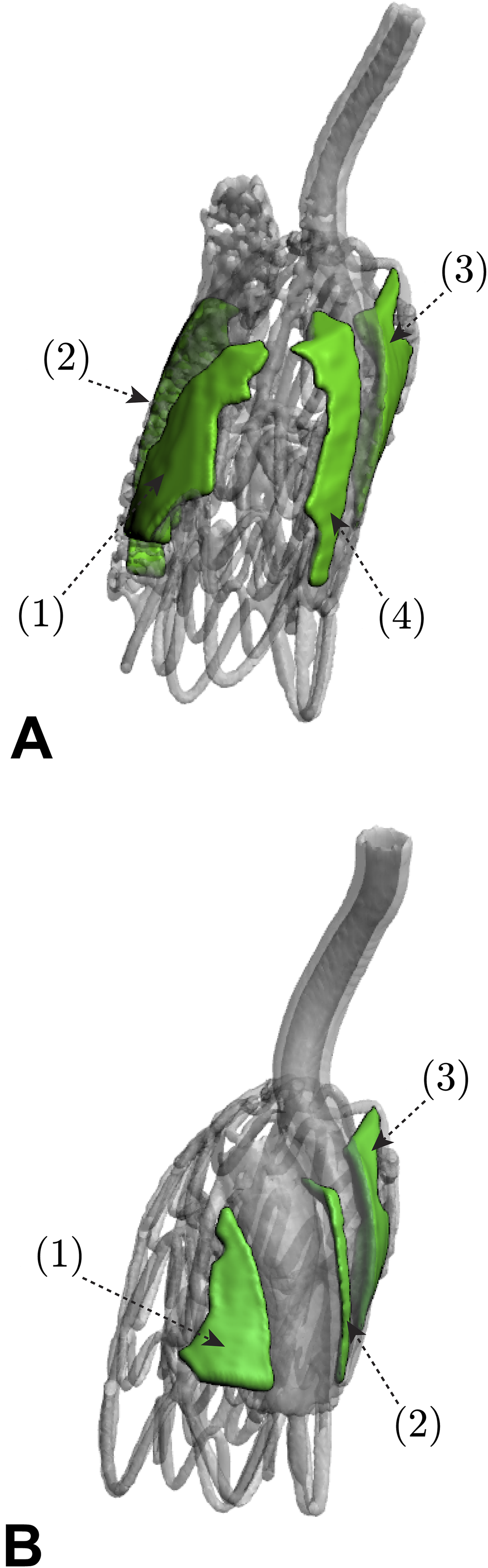
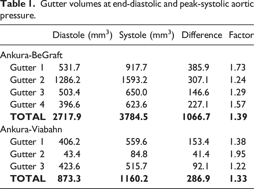
The largest single gutter volumes were determined to be 1593.2 mm3 and 559.6 mm3 in the BE and SE configurations, respectively, both during systole. All gutter volumes were found to increase from end-diastolic to peak-systolic aortic pressure, with largest volumetric increase found in the BE configuration (Gutter 1, 385.9 mm3). Differences in gutter volumes between configurations were not found to be statistically significant for either end-diastolic or peak-systolic aortic pressures (p = .20 and p = .12, respectively). Change in gutter volume between diastole and systole was statistically significant for the BE configuration (p = .014), but was not significant for the SE configuration (p = .098). Differences in gutter volume change during the cardiac cycle between configurations were not found to be significant (p = .0504).
A total of seven gutter pairs were overlaid, co-registered (see Supplemental Materials 4 and 5), and subsequently analysed using the surface deviation approach to quantify the behaviour of gutter geometry between end-diastolic and peak-systolic pressure. A representative analysis case is illustrated in Figure 5. Representative case of geometrical gutter analysis (Gutter 1, Ankura-BeGraft) including diastolic (blue) and systolic (red) gutter overlay, co-registration, and surface deviation quantification. Gutter as viewed to (top) vessel-bound surface aspect; (middle) endograft-bound surface aspect; (bottom) inlet at level of Ankura graft covering. Gutter location included for reference. Note: surface deviation map displayed on systolic gutter surface; positive surface deviation indicates regions where diastolic gutter lies external to systolic gutter.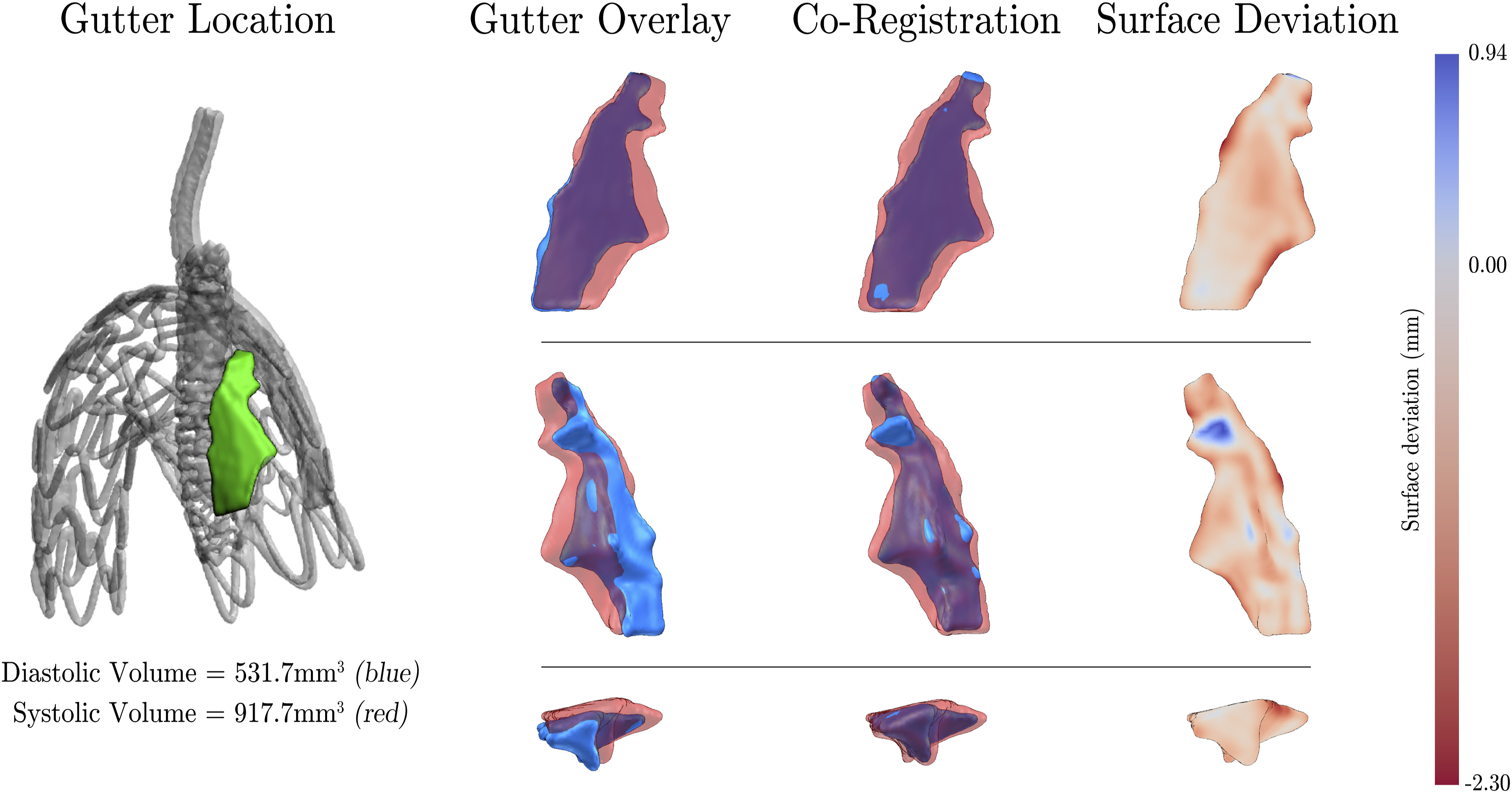
Geometric variation (surface deviation) of gutters between diastolic and systolic cardiac phases. Data reported as mean (maximum) values of co-registered gutter pairs.
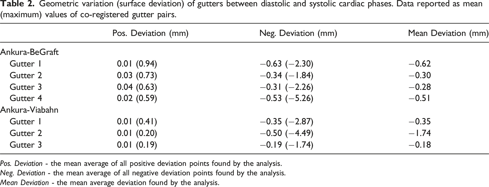
Pos. Deviation - the mean average of all positive deviation points found by the analysis.
Neg. Deviation - the mean average of all negative deviation points found by the analysis.
Mean Deviation - the mean average deviation found by the analysis.
Maximum mean negative surface deviations of −5.26 mm and −4.49 mm were found for the BE and SE configurations, respectively. These large deviations are associated with geometric changes located in the distal region of the gutter, approaching the aortic arch. Mean surface deviations were found to be −0.43 mm and −0.34 mm in the BE and SE configurations, respectively. Differences in mean surface deviations between BE and SE configurations were not determined to be statistically significant (p = .52).
Endograft compression during the cardiac cycle
The D-ratios for both experimental configurations are presented in in Figure 6. Key measures along the constructed CLLs including maximum, minimum, and average D-ratios, as well as the change between end-diastolic and peak-systolic aortic pressure, are reported in Table 3. D-ratios of (A) Ankura-BeGraft and (B) Ankura-Viabahn double chimney TEVAR configurations at end-diastolic (dashed line) and peak-systolic (solid line) aortic pressures measured along the central lumen lines. (BT) Device deployed into brachiocephalic trunk; (LCCA) device deployed into left common carotid artery. Position 0 mm refers to the proximal covered edge of each device. Key measures of main and chimney endograft D-ratios between end-diastolic and peak-systolic aortic pressure as measured along the central lumen lines. BT: brachiocephalic trunk; LCCA: left common carotid artery.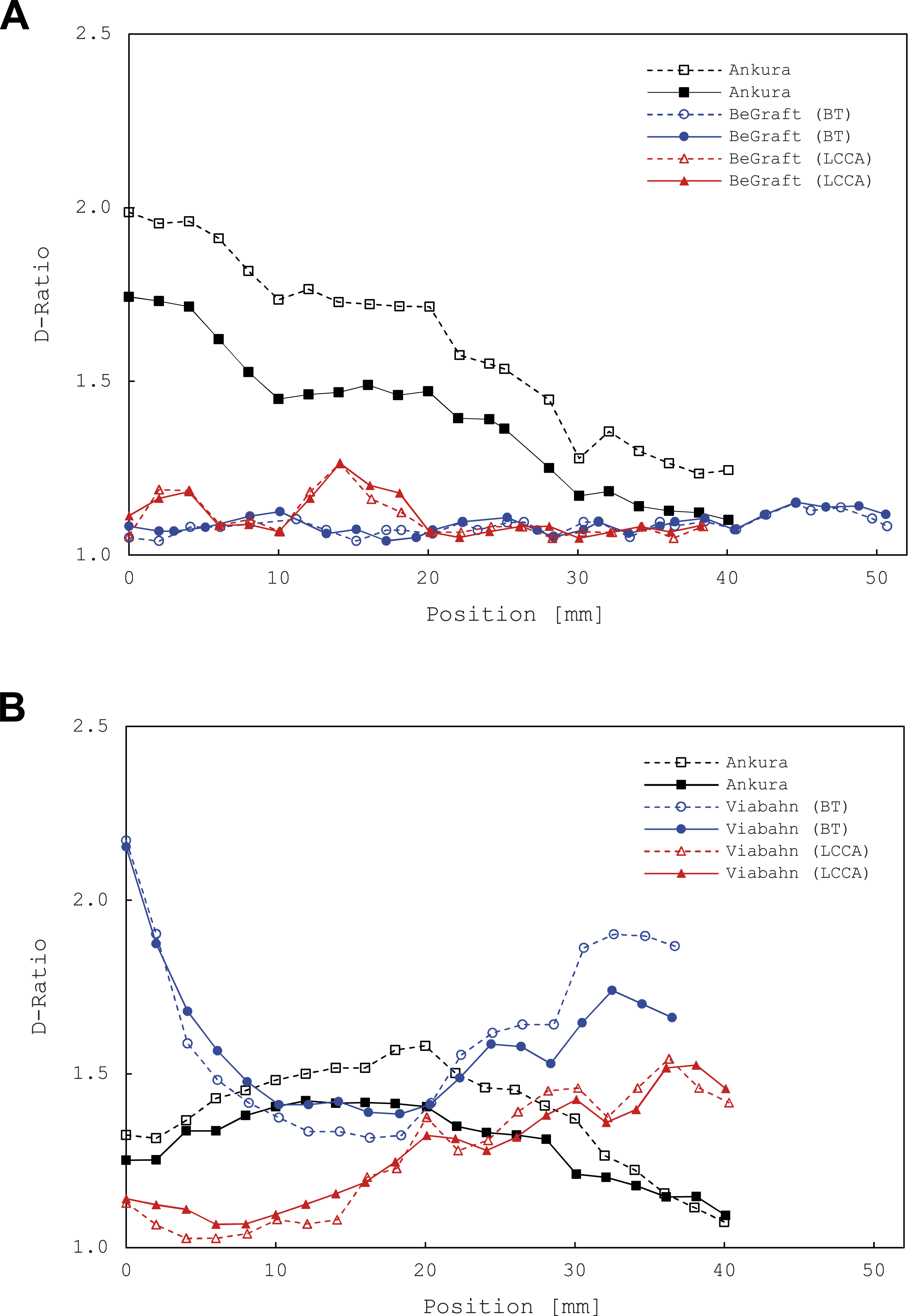
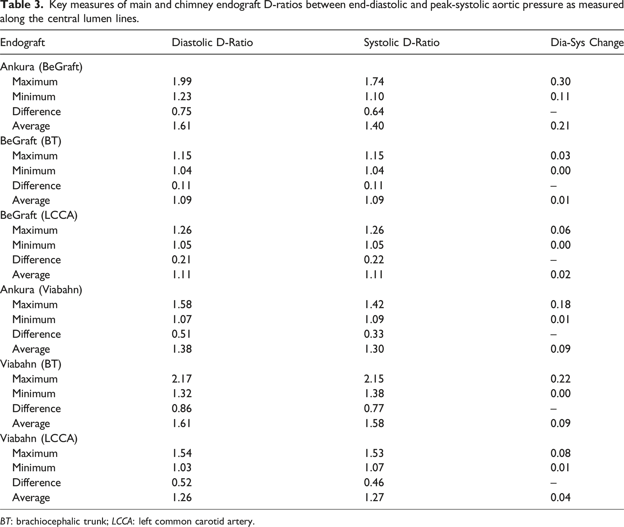
For the BE double chimney configuration, the Ankura device exhibited the largest D-ratio (1.99, end-diastolic pressure), with the change between end-diastolic and peak-systolic behaviour determined to be statistically significant (p < .001). BeGraft devices deployed into the BT and LCCA experienced absolute maximal D-ratio changes of 0.03 and 0.06, respectively, but were not statistically significant (p = .17 and p = .38, respectively). When considering positional variation, both BeGrafts exhibited relatively uniform D-ratios along their length, whilst the Ankura device exhibited a consistent downward trend.
In the SE double chimney configuration, the Viabahn device deployed into the BT exhibited the largest (and largest overall) D-Ratio ratio (2.17, end-systolic pressure). However, in a manner similar to the BE configuration, only changes in the Ankura D-ratio between end-diastolic and peak-systolic aortic pressure were statistically significant (p < .001). When considering positional variation, it was observed that the D-ratios of both SE devices noticeably change along their length.
When comparing inter-experimental results, only differences between Ankura D-ratio changes were statistically significant (p < .001), whilst changes in CG D-ratios were not (p = .12 and p = .85, for BT and LCCA devices, respectively).
Discussion
The results of the present study demonstrate that both BE and SE covered chimney stents, when deployed in a double ch-TEVAR configuration, result in gutter formation. Notably, the BE configuration resulted in 3 times the total gutter volume in comparison to its SE counterpart, which extends the results of previously reported ch-EVAR/EVAS studies15,16,21,22 to the ch-TEVAR case. Indeed, gutters may be inherent to this endovascular technique, 23 regardless of CG type or anatomical location. Quantitatively, comparison of absolute gutter volumes with other reported studies is inappropriate given the difference in devices, anatomies, and measurement techniques employed. Nevertheless, Niepoth et al. 14 reported total gutter volumes up to 960 mm3 over a seal zone of 20 mm for a single BE ch-EVAR case (derived from two gutters). Considering additional gutters have been identified in the model employed here (four gutters in the case of BE ch-TEVAR), as well as longer seal zones (up to approximately 45 mm in case of Gutter 2), the total gutter volumes for both BE and SE configurations are reasonable.
Importantly, it was shown that ch-TEVAR gutter volumes vary dynamically between phases of the cardiac cycle, corroborating a recent ch-EVAR study by Overeem et al. 16 The most substantial change in gutter volume between end-diastolic and peak-systolic aortic pressure was associated with the BE configuration, with only a small change in volume noted in the SE case. These findings further support the recommendation that gated CT, or similar, should be used during follow-up of patients treated with CGs to better identify persistent endoleak which may otherwise go undetected. 16
The difference in gutter volume changes during the cardiac cycle was also evaluated in this work. The nearly 4-fold difference between BE and SE configurations suggests that either CG type or deployed arrangement (opposite clock-face orientation vs adjacent), or both, may influence how gutters may behave dynamically in vivo. Such influences could in turn affect the risk of type 1a endoleak. Given the low sample size in this study, and uncontrolled implant positioning between groups, exact inferences could not be made. Nevertheless, these findings further support the notion that there exists an underlying structure-function relation, primarily attributed to the native properties of nitinol, 24 that may influence the optimal configuration of devices in chimney-type procedures.15,23
To the best of the authors knowledge, there exist only two reports illustrating a volumetric reconstruction of an in vitro chimney-related gutter,14,25 and no reports on either the geometrical changes during the cardiac cycle, or specific to ch-TEVAR. Accordingly, this investigation provides compelling insights into the dynamic geometrical behaviour of gutters. Qualitatively, it can be observed in the configurations presented here that distinct gutter geometries exist at different phases of the cardiac cycle. Again, it is postulated that this dynamic behaviour is likely owing to both spatial positioning and device type. Recent reports have described the treatment of chimney-related type 1a endoleak using embolic agents. 26 Indeed, the illustrative observations reported here, coupled with the quantification of surface deviations, may serve to inform how endoleaks should be treated using such techniques.
Similarly, there have been no in vitro studies or clinical reports describing chimney deformation when devices are deployed in an adjacent fashion parallel to a primary endograft. In general, the D-ratios reported here follow trends reported elsewhere,16,23 namely: SE covered chimney grafts exhibit higher degrees of deformation compared to their BE counterparts. The distinctly unique findings of this study, however, are derived from the observed interactions of the adjacent self-expandable CGs deployed into the brachiocephalic trunk and left common carotid artery, as manifested by their varying lumen deformations (Figure 6(B)). When in contact, CGs appear to support each other, and as such, tend towards a more consistently circular shape. Such observations corroborate recent benchtop studies 27 and warrant further investigation, as adjacent deployment of CGs in double ch-TEVAR may reduce incidence of device compression thereby improving long-term patency rates.
Limitations
First, a single, healthy thoracic aortic model was used for simulated double ch-TEVAR. Given that a healthy aortic landing zone is a prerequisite for endovascular repair, and that complications during ch-TEVAR are most likely to be associated with device behaviour at the landing zone, use of such a model was deemed to be appropriate. Regarding the experimental setup, it should also be noted that flow rates were not quantified, nor was a truly physiological pressure profile used. Secondly, contrast agent was not used during imaging. Although contrast may have improved intensities between the lumen, vessel wall, and endograft frames, initial CT data collection revealed the data to be of sufficient quality. Likewise, the variance in material properties between BE and SE chimney devices may result in differences in attenuated imaging signal, affecting both gutter and D-ratio measurements. 16 Finally, only a single main endograft was used in this study, limiting observations to the specific device combinations discussed. While the Ankura device has limited use in Western interventional centers, recent reports have demonstrated its safety and effectiveness in traditional TEVAR 28 and its utility in double ch-TEVAR. 29 The methods developed in this study could be duplicated for other TEVAR main body devices to characterise synonymous behaviour.
Conclusion
In this study, two different double ch-TEVAR configurations have been evaluated in an in vitro thoracic aortic model. Gutter and chimney graft behaviour were dependent on device type, and exhibited both spatial and temporal variability. The configuration employing BE chimney grafts resulted in increased gutter volumes and gutter volume changes across the cardiac cycle compared to its SE counterpart. This is the first report to include detailed volumetric reconstructions of ch-TEVAR gutter volumes, describe surface deviations as a metric to characterise dynamic gutter phenomena, as well as show decreased chimney graft lumen deformation when multiple SE devices are deployed adjacently. These findings suggest the importance of cardiac-gated imaging for ch-TEVAR endoleak risk assessment, and provide important data for the strategy and design of novel ch-TEVAR techniques and devices.
Supplemental Material
Supplemental Material - In vitro quantification of stent-graft behaviour during chimney thoracic endovascular aortic repair
Supplemental Material for In vitro quantification of stent-graft behaviour during chimney thoracic endovascular aortic repair in Jakub Kwiecinski, Raman Uberoi, Mohammed Hadi, Christopher P Cheng and Zhong You in Vascular
Footnotes
Acknowledgements
The experiments presented in this work were performed at the John Radcliffe Hospital (Oxford, UK). Special thanks to JR Radiology staff Helen Nicole, Lesley Brougham, and Kader Benadel for their support. Materials and equipment were generously provided by Elastrat Sàrl (Geneva, Switzerland), United Biologics Inc. (Santa Ana, CA, USA), Medical Implant Testing Lab Inc. (Irvine, CA, USA), Lifetech Scientific Co. Ltd. (Shenzhen, China), and Bentley Innomed GmbH (Hechingen, Germany).
Declaration of conflicting interests
The author(s) declared the following potential conflicts of interest with respect to the research, authorship, and/or publication of this article: Authors Jakub Kwiecinski, Raman Uberoi, Mohammed Hadi, Christopher P. Cheng, and Zhong You declare that they have no conflict of interest.
Funding
The author(s) received no financial support for the research, authorship, and/or publication of this article.
Supplemental Material
Supplemental material for this article is available online.
References
Supplementary Material
Please find the following supplemental material available below.
For Open Access articles published under a Creative Commons License, all supplemental material carries the same license as the article it is associated with.
For non-Open Access articles published, all supplemental material carries a non-exclusive license, and permission requests for re-use of supplemental material or any part of supplemental material shall be sent directly to the copyright owner as specified in the copyright notice associated with the article.