
Abstract
A method for designing asymmetric multi-mode parallel mechanism is proposed. Parallel mechanisms with 2R1T and 2T1R motion modes are synthesized by using displacement manifold theory. Based on the parallel mechanism, a kind of mechanism with hybrid variable DOF kinematic chain is proposed. The DOF characteristics of the mechanism in the process of motion mode transformation are analyzed by using screw theory, and the rationality of the selection of driving pairs in different motion modes is verified. The results show that the mechanism with hybrid variable DOF kinematic chain has 3R, 2T1R, and 2R1T motion modes. When the mechanism is in the general configuration of the four motion modes mentioned above, three driving pairs can control the mechanism. When the mechanism is in the transformation configuration having 2R2T or 3R1T instantaneous DOF, an additional auxiliary driving pair is needed to control the mechanism. The mechanism can realize multiple motion modes by using fewer driving pairs. It does not need to reassemble the mechanism when the motion mode is changed.
Keywords
Introduction
Parallel mechanisms with multiple motion modes are also called parallel mechanisms with multiple operation modes, variable displacement subgroups, bifurcation motion, or reconfigure ability. Its characteristics are as follows: Fewer driving pairs can realize multiple motion modes; There is no need to reassemble the mechanism when the motion mode is transformed, so the mechanism can be reconstructed quickly. Some of these parallel mechanisms need to pass the singular configuration of the mechanism when the motion mode is transformed. 1
DOMY 2 parallel mechanism has four different3-DOF motion modes. This mechanism contains special kinematic chains, and Hunt 3 firstly analyzed its characteristics when he studied the universal hubs. Geometric algebraic method is used to analyze the types of motion modes of this kind of mechanism with bifurcation of motion.4,5 The bifurcation characteristics of single-loop mechanism are analyzed in the literature. 6 The coaxial or parallel of rotation axis and moving direction is considered as the critical condition for the transformation of mechanism motion modes. Based on this, some mechanisms with multiple motion modes are designed. In the literature, 7 the singularities of bifurcations of mechanisms are classified, and some parallel mechanisms with multiple modes of motion are designed. 8 The principles of designing reconfigurable mechanisms are classified into three categories 9 : variable topology, variable geometry, and bifurcation of motion. Lie group theory is used to analyze the bifurcation characteristics of 6R mechanism. 10 This kind of single-loop mechanism with bifurcation characteristics is used to design parallel mechanism with multiple motion modes. Literature 11 synthesizes parallel mechanisms which could realize the transformation of 3-DOF motion modes of 3T, 3R, 2R1T, and 2T1R. The bifurcation of motion of some single-loop mechanisms is discussed by using geometric method in the literature.12–14 Inspired by the above ideas,15,16 a large number of single-loop mechanisms with motion bifurcation are designed by using the intersection of geometric surfaces to generate bifurcated curves. Literature 17 synthesizes the parallel mechanism of schoenflies motion with two different rotation directions by using Lie group theory. A kind of 3T1R parallel mechanism with variable rotation axis 18 is designed by using finite displacement screw theory. Zeng 19 classified the kinematic chains, sorted out some kinematic chains with variable DOF. The screw theory is used to analyze the kinematic bifurcation of the 3-PUP parallel mechanism. 20 Based on the inspiration of carton forming, some single-loop mechanisms with motion bifurcation are designed, 21 and based on this, some parallel mechanisms with multiple motion modes are designed. Matrix is used to represent the structure of variable topology mechanism. 22 Some kinematic pairs 23 which can transform the motion mode are proposed. These kinematic pairs can be used to design multiple mode parallel mechanism. A fully symmetrical parallel mechanism with 2R1T and 3R motion modes is designed by using reconfigurable rotation pairs. 24 In the literature, 25 virtual kinematic chains are used to synthesize the kinematic chains of parallel mechanisms with different motion modes. The common kinematic chains of two motion modes are selected as the optional kinematic chains. Combined with the geometric conditions of kinematic chains assembly with different motion modes, the parallel mechanisms with multiple kinematic modes are synthesized. The equivalent pair of spherical pairs is made up of lockable RRR spherical kinematic chains, which realizes the transformation of motion modes. 26 In the literature, 27 the over-constrained 6R mechanism is used as a moving platform, and the motion mode of the mechanism is changed by locking and releasing the kinematic pair.28,29 In the literature, some parallel mechanism with multiple motion modes are designed by using double-loop mechanism with linear driving pairs. 30 A kind of redundant parallel mechanism is designed with two platforms. 31 When the motion mode of the mechanisms changes, the number of DOF changes. 32 In the literature, 33 A redundant kinematic pair is used to design parallel mechanisms with 2T1R and 2R1T modes. The motion modes of this kind parallel mechanisms is limited. When it implements different tasks or realizes motion mode transformation, it actually needs more driving pairs. Literature 34 suggests ways to realize motion mode transformation. Literature 35 designes a 6-DOF stewrt parallel mechanism Using multiple SPS kinematic chains with overlapping spherical joints, which could change the stiffness of 6-DOF stewrt parallel mechanism by locking the driving pair. Literature 36 studies multiple motion modes of mechanisms based on high-order kinematics, and finds some mechanisms with new motion characteristics.
The research on intelligent reconfigurable mechanisms and robots with the ability to actively adapt to changeable environment and passively adapt to emergencies is of great significance to the innovation and development of advanced manufacturing field and a new generation of robots. There are few existing multi-mode, reconfigurable parallel mechanisms. The innovative design of multi-mode parallel mechanism is an important research content of mechanism. The synthesis of parallel mechanisms with multiple motion modes is still one of the hot spots of mechanism research. Generally, the performance of symmetrical parallel mechanism is better. However, when the structure of multi-mode parallel mechanism is symmetrical, the number of degrees of freedom increases more during motion mode transformation, so multiple driving pairs are required to realize motion mode transformation.
In this paper, a method for designing asymmetric multi-mode parallel mechanism is proposed. This kind of mechanism only increases one degree of freedom during the transformation of motion mode, so that after adding an auxiliary driving pair, it can realize the transformation between multiple motion modes with other three driving pairs, which fully reflects the characteristics of multi-mode mechanism using fewer driving pairs to realize multiple tasks.
The paper is organized as follows. In Section “Synthesis of kinematic chain,” The variable DOF kinematic chain which construct the mechanism that have 2R1T and 2T1R motion mode is synthesized by using displacement manifold theory. In Section “Parallel mechanism with 2T1R and 2R1T motionmodes,” one fix DOF kinematic chain, one 6-DOF kinematic chain, and one 5-DOF kinematic chain with variable DOF are constructed to from a parallel mechanism which has 2R1T and 2T1R motion modes. The DOF characteristics of parallel mechanism with 2R1T and 2T1R motion modes that are analyze by using screw theory. In Section “Parallel mechanisms with 2T1R, 3R, and two 2R1Tmotion modes,” the DOF of mechanism with 2T1R, 3R, and 2R1T motion modes is analyzed by using screw theory, and the rationality of the selection of driving pairs in different motion modes is verified. In Section “2R1T motion modes,” the two 2R1T motion modes are distinguished. The Section “Conclusion” drawn two conclusions.
Synthesis of kinematic chain
The coordinate system is represented by (

There are seven equivalent kinematic chains of {G(
Constructing a kinematic chain with fixed DOF
The literature 37 gives the detailed calculation results of intersection and multiplication of two displacement subgroups, and points out that the calculation of the intersection of the displacement subgroups satisfies the intersection rule in the general set theory. In more cases, the rigid body motion generated by the kinematic chain (composed of multiple pairs of motion) can not satisfy the algebraic structure of the displacement group, only is the displacement sub manifolds.
kinematic pairs and chains can be directly used as generators of displacement subgroups or displacement sub manifolds. Correspondingly, any motion at the output link of the chain relative to the fixed platform, no matter how complicated it is, it can be expressed as several displacement subgroups or displacement sub manifolds and their product forms. Usually, the motion of the output link of kinematic chain can be determined by the product of the displacement subgroups generated by all the pairs in the kinematic chain. The product of these displacement subgroups may still be displacement subgroups, but in most cases this product does not have the algebraic structure of groups, is only a displacement sub manifold.
M = M1||…Mk represents a parallel mechanism consisting of K series kinematic chains M1…Mk. They are all connected with common moving and fixed platforms. Symbol C is used to represent the motion of the output link of the mechanism, then the motion of the moving platform of the parallel mechanism can be expressed as:

Formula (2) shows that the motion of the moving platform should be the intersection of motion of the kinematic chain of the parallel mechanism.
Theorem 1. The product motion A·B of an arbitrary displacement subgroup may constitute a displacement subgroup, or it may do not have the algebraic structure of the group, is only a displacement sub manifold.
Generally speaking, the commutation law is not satisfied, that is A·B ≠ B·A. But if the law A·B = B·A is satisfied, then A·B is a displacement subgroup. Since the motion mode of the moving platform of the parallel mechanism will change from 2T1R to 2R1T, the calculation of the intersection of equation (2) shows that the kinematic chain of the parallel mechanism should realize at least 2R2T motion. 2T1R is a plane displacement subgroup {G(
Since the 6-DOF kinematic chain does not acts constraint on the moving platform, it can also be used to construct parallel mechanism to realize the transformation from 2R1T motion mode to 2T1R motion mode. Gougu uses evolutionary morphology theory to synthesize 6-DOF kinematic chains, 38 such as: P||R⊥P||R⊥P||R, P⊥P⊥P-S, P⊥P⊥R-S, P⊥P||R-S, P||R⊥P-S, P||R⊥P-S, P⊥R⊥R-S, P||R⊥R-S, P||R||R-S, R⊥P⊥||P-S, R||P⊥P-S, R⊥P⊥⊥R-S, R⊥P||R-S, R||P||R-S, R||P⊥R-S, R⊥R⊥P-S, R||R||P-S, R⊥R||P-S, R⊥R||R-S, R||R⊥R-S, R⊥R⊥R-S, P-S-S, R-S-S, S-P-S. Local DOF exist in P-S-S, R-S-S, and S-P-S kinematic chains, but not in other kinematic chains. In addition to the above-mentioned kinematic chains, some complex kinematic chains, also have 6 DOF.
Selection of kinematic chains with variable DOF based on displacement manifold theory
Generally, the kinematic chain structure of parallel mechanisms can be obtained from the generators of displacement subgroups or manifolds. The kinematic chain displacement manifold with fixed DOF is as follows:

According to the motion mode of the moving platform, which has 2R1T and 2T1R motion modes, the variable DOF kinematic chain generator is constructed.
Since {R(O,

Since the intersection of {R(A,

Since {T1(

{R(A,

Formula (8) yields:

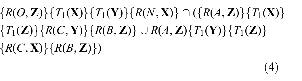
According to formulas (4) and (9), the displacement manifold generator which can realize the transition from 2R1T motion mode to 2T1R motion mode should has the following form:

Generator in formula (10) correspond to kinematic chains


Configuration of
kinematic chain shown in Figure 1 enable the parallel mechanism with the kinematic chain to realize the transformation of motion modes.
Parallel mechanism with 2T1R and 2R1T motion modes
2T1R motion mode configuration
According to the displacement manifold in the equation (3), kinematic chain

Parallel mechanism with 2T1R motion mode.
The platform A1A2A3 in Figure 2 has 3 DOF. It shows that the platform A1A2A3 has two moving DOF along fixed coordinates X and Y, and one rotation DOF around the axis parallel to the fixed coordinates Z axis, that is, it has 2T1R motion mode. According to the method in reference, 39 the instantaneity of the DOF of the mechanism can be determined. For each DOF of the corresponding mechanism, a small enough displacement from the initial position of the mechanism is given in turn, and then determine whether the DOF of the mechanism changes. If it changes, the DOF of the mechanism is instance, If it does not change, the DOF of the mechanism is not instance. It can be verified that the 2T1R DOF of the mechanism at the configuration of Figure 2 is not instantaneous.
The process of transforming motion mode
The rotation shafts of kinematic chain 2 are co-linear
The mechanism at the configuration shown in Figure 2 makes finite displacement at the XOY plane, and then two shafts

Parallel mechanism with instantaneous 1T1R DOF.
The moving platform in Figure 3 has 2 DOF. It shows that at the mechanism configuration shown in Figure 3, the platform A1A2A3 has one moving DOF along the X axis of the fixed coordinate system and 1 DOF of rotation around the axis z2. When the platform A1A2A3 makes limited displacement along the X axis of the fixed coordinate system, the platform A1A2A3 is in the motion mode of the mechanism shown in Figure 2, and the DOF of the mechanism at the configuration of Figure 2 is not instantaneous, so the DOF of the mechanism at the configuration of Figure 3 is instantaneous. At the configuration shown in Figure 3, the position and posture of the platform A1A2A3 remain unchanged. After the second kinematic chain rotates 90° around the axis z2, the planar displacement sub-group chain

Parallel mechanism with instantaneous 2T2R DOF.
Motion mode transforming configuration
At the mechanism configuration shown in Figure 4, when the platform A1A2A3 moves along the Y axis of the fixed coordinate system, 1 DOF will be added in the second kinematic chain. It shown that the moving platform has a 2R2T motion mode; when the platform A1A2A3 rotates around the axis parallel to the X axis of the fixed coordinate system, the moving platform has a 2R1T motion mode. Therefore, the motion mode at the configuration of the mechanism shown in Figure 4 is instantaneous.
2R1T motion mode configuration
When the platform A1A2A3 rotates finitely around the axis parallel to the X axis of the fixed coordinate system in the configuration shown in Figure 4, the configuration of mechanism is shown in Figure 5.

Parallel mechanism with 2R1T DOF.
The platform A1A2A3 in Figure 5 has 3 DOF. It shows that the platform A1A2A3 has one moving DOF along the Y axis of the fixed coordinate system and two rotation DOF parallel to the X and Z axis of the fixed coordinate system. That is, when the mechanism is in the configuration shown in Figure 5, the platform A1A2A3 has 2R1T motion mode. It can be verified that the 2R1T DOF of the mechanism at the configuration of Figure 5 is not instantaneous.
Parallel mechanisms with 2T1R, 3R, and two 2R1T motion modes
When the parallel mechanism has 3R, 2R1T, and 2T1R motion modes, the instantaneous DOF of the mechanism will increase when the mechanism is in the transformation configuration of the motion mode. In order to use fewer driving pairs realize the transformation of the above motion modes, it is necessary to avoid the transformation of the motion mode of the mechanism when it has three motion modes at the same time. When the motion mode of the mechanism changes from one to another, and only 1 DOF is changed, the DOF of the mechanism is increased by one at the motion mode transformation configuration of the mechanism. If the DOF of the mechanism changes more than one, the DOF of the mechanism at transformation configuration will also increase more than one. It is necessary to add several auxiliary driving pairs to realize the transformation of the mechanism motion modes, which increases the difficulty of the control of the mechanism and the cost of machine equipment. Therefore, the motion mode of the mechanism can be transformed from 2T1R motion mode to 3R motion mode by following six steps. The first step: the motion mode of the mechanism can be transformed from 2T1R motion mode to 2R2T instantaneous DOF; The second step: the instantaneous 2R2T DOF of the mechanism can be transformed to 2R1T motion mode; The third step: the motion mode of the mechanism can be transformed from 2R1T motion mode to 3R1T instantaneous DOF; The fourth step: the instantaneous 3R1T DOF of the mechanism can be transformed to another 2R1T motion mode which is different from the 2R1T motion mode in second step; The fifth step: the motion mode of the mechanism can be transformed from 2R1T motion mode to 3R1T instantaneous DOF; The sixth step: the instantaneous 3R1T DOF of the mechanism can be transformed to 3R motion mode. At the first and second steps, the motion mode of the mechanism is transformed from the original 2T1R motion mode to 2R1T motion mode. One moving DOF of the mechanism in the 2T1R motion mode is transformed into one rotation DOF. The motion mode of the mechanism is transformed at the 2R2T instantaneous configuration of the mechanism, and the DOF of the mechanism is increased by one. At the third and fourth steps, the motion mode of the mechanism is transformed from 2R1T motion mode to another 2R1T motion mode. The direction of one rotation DOF of the mechanism is transformed into another direction that make this two 2R1T motion modes different. The motion mode of the mechanism is transformed at the 3R1T instantaneous configuration of the mechanism, and the DOF of the mechanism is increased by one. At the fifth and sixth steps, The motion mode of the mechanism is transformed from 2R1T motion mode to 3R motion mode. One moving DOF of the mechanism in the 2R1T motion mode is transformed into one rotation DOF. The motion mode of the mechanism is transformed at the 3R1T instantaneous configuration of the mechanism, and the DOF of the mechanism is increased by one. In theory, only one auxiliary driving pair is needed to realize the transformation of the motion mode of the mechanism, which is helpful to reduce the difficulty of the control of the transformation of the motion mode of the mechanism and the manufacturing cost of the machinery and equipment.
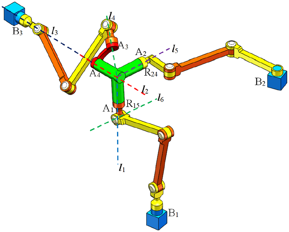
In order to design mechanisms with 3R, 2R1T, and 2T1R motion modes, a hybrid variable DOF kinematic chain and a variable DOF kinematic chain can be used to construct the mechanisms. In Section “Parallel mechanism with 2T1R and 2R1T motionmodes,” the mechanism shown in Figure 2 has 2R1T and 2T1R motion modes. A rotation pair is connected in series on its platform to form a hybrid variable DOF kinematic chain, whose output link has 3R1T and 2T2R motion modes. As shown in Figure 6, the fixed platform of the mechanisms is B1B2B3, and the fixed coordinate system OXYZ consolidated with it; The moving platform is A3A4, and the moving coordinate system oxyz consolidated with it. The kinematic chain structure connecting B1 and A1 is

Mechanism at 2T1R motion mode: (a) a sketch of parallel mechanism and (b) 3-D model of parallel mechanism.
2T1R motion mode
DOF analysis of the mechanism at 2T1R motion mode configuration
As shown in Figure 6, the coordinate system Bix i y i z i parallel to the coordinate system OXYZ is established at Bi point and the rotation pair R4 is connected in series with the link A1A2A4. The kinematic chain B1A1, B2A2, the link A1A2A4, and the rotation pair R4 can be regarded as the hybrid kinematic chain. The DOF of the mechanism shown in Figure 6 can be analyzed by the following two methods. The first method is that regarding A3A4 as the moving platform, and then calculates the constraint screws of the kinematic chain B1A1 and B2A2 act on the link A1A2A4.
Calculating the kinematic screws of the link A1A2A4, and then obtains the kinematic screws of the hybrid kinematic chain. Finally calculating the constraint screws of the hybrid kinematic chain acts on the moving platform A3A4. The DOF of the moving platform A3A4 is calculated by combining the constraint screws acted on the moving platform A3A4 by the kinematic chain B3A3. The first method can also be used to calculate the driving screw produced by the driving pair. However, this method need a large amount of calculation. The second method, the link A1A2A4 in Figure 2 can be regarded as the moving platform. The kinematic chain B1A1 is the first kinematic chain, the kinematic chain B2A2 is the second kinematic chain, and the kinematic chain B3A3 connects a rotation pair R4 that constructs the third kinematic chain. The DOF of the mechanism shown in Figure 6 after locking the driving pairs can be calculated. By using this method, the mechanism with hybrid kinematic chain can be transformed into parallel mechanism, which is convenient for constraint screws and driving screws analysis. The first method is used to analyze the motion mode of mechanism. The second method is used to calculate the DOF of the mechanism after locking driving pairs. Combining with the 2T1R motion mode of the mechanism shown in Figure 2, the kinematic screws group of the hybrid kinematic chain in coordinate system B1x1y1z1 in Figure 6 can be expressed as follows:

The screw

Similarly, the constraint screws acted on the platform A3A4 by the kinematic chain B3A3 in the coordinate system B3x3y3z3 can be expressed as

The constraint screws acted on the platform A3A4 by the hybrid kinematic chain B1A1B2A2-R4 and B3A3 can be transformed from the local coordinate system B1 and B3 to the fixed coordinate system OXYZ for overall analysis. In the fixed coordinate system OXYZ, it can be expressed as follows:
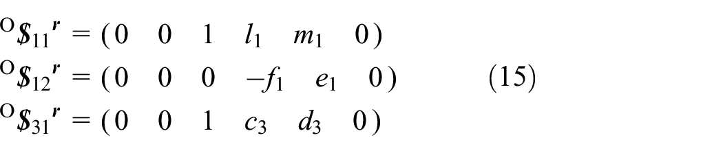
O
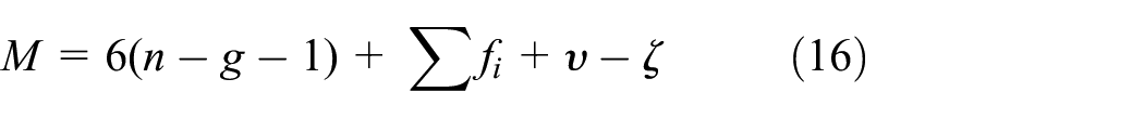
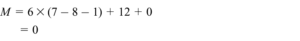
In formula (16), M: DOF of mechanism, n: total number of links, g: number of kinematic pairs of mechanism, fi: number of freedom of the kinematic pair, υ: number of redundant constraints, ζ: passive DOF. It is worth noting that in Figure 6, the hybrid kinematic chain B1A1B2A2-R4 can be equivalent to

The mechanism has 3 DOF. Calculating by reciprocal product operation on the constraints on the platform A3A4, it can be seen that the mechanism has 2T1R motion mode at the configuration shown in Figure 6, that is two moving DOF along the XOY plane and one rotation DOF around the axis parallel to Z axis. It can be verified that the 2T1R DOF of the mechanism at the configuration of Figure 6 is not instantaneous.
Rationality analysis of driving pairs selection at 2T1R motion mode configuration of the mechanism
Whether the selection of driving pairs of parallel mechanism are reasonable can be verified by calculating the DOF of the mechanism after driving pairs are locked in kinematic chains. When the DOF of the mechanism is zero with driving pairs in kinematic chains are locked, the selection of the driving pairs are correct. Otherwise, the driving pairs selection are wrong. At the mechanism configuration shown in Figure 6, the rotation pair R13 in the kinematic chain B1A1, the rotation pair R21 in the kinematic chain B2A2, and the rotation pair R33 in the kinematic chain B3A4 are used as the driving pairs. At the mechanism configuration shown in Figure 6, the kinematic chain B3A4 does not act constraint on the link A1A2A4, and the constraint screws group acted on the link A1A2A4 by the kinematic chains B1A1 and B2A2 are

In formula (17), O

O
The mechanism has 0 DOF. It can be seen that at the mechanism configuration shown in Figure 6, three driving pairs selected can realize the control of mechanism in 2T1R motion mode.
2R2T DOF configuration
DOF analysis of the mechanism at 2R2T DOF configuration
The mechanism can moves in plane from the configuration shown in Figure 6 to the configuration shown in Figure 7. At this configuration, the axes

2R2T motion mode configuration of mechanism.
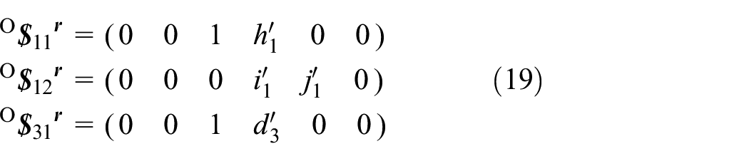
In formula (19), O

The mechanism has 4 DOF. Calculating by reciprocal product operation on the constraints group acted on moving platform A3A4, it can be seen that the moving platform A3A4 has two rotation DOF parallel to the axis
Rationality analysis of driving pairs selection at instantaneous 2R2T DOF configuration of the mechanism
Locking the rotation pair R13 in the kinematic chain B1A1, R21 in the kinematic chain B2A2, and R33 in the kinematic chain B3A4. The driving force screws acted on the link A1A2A4 by the kinematic chains B1A1, B2A2 and B3A4 are as follows:

In formula (20), O

Because the linear vector of the constraint screw O

The mechanism has 1 DOF. It can be seen that at the configuration shown in Figure 7, the three selected driving pairs can not realize the control of the mechanism at the 2R2T instantaneous DOF configuration.
Selection of auxiliary driving pair for mechanisms at 2R2T instantaneous DOF configuration
According to the analysis results of section “Rationality analysis of driving pairs selection at instantaneous 2R2T DOF configuration of the mechanism,” after locking the rotation pair R13 in the kinematic chain B1A1, R21 in the kinematic chain B2A2, and R33 in the kinematic chain B3A4, the control of the mechanism at the instantaneous DOF configuration of 2R2T can not be realized. Therefore, it is necessary to increase one auxiliary driving pair and select R31 as the auxiliary driving pair in the kinematic chain B3A4. After locking the auxiliary driving pair, the driving force is not acted on the link A1A2A4. The modified Kutzbach-Grübler formula is used to calculate the DOF of the mechanism. The mechanism in Figure 7 has 7 links, 8 joints, and 11 single DOF kinematic pairs after driving pairs are locked. The number of redundant constraints is 1. There is no passive DOF.
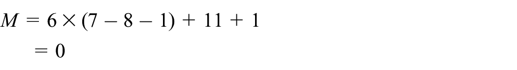
It can be seen that at the configuration of the mechanism shown in Figure 7, three driving pairs and one auxiliary driving pair R31 can realize the control of the mechanism in the 2R2T instantaneous DOF configuration.
2R1T DOF configuration
DOF analysis of the mechanism at 2R1T motion mode configuration
When three driving pairs and one auxiliary driving pair of the mechanism shown in Figure 7 are controlled so that the mechanism moving platform A3A4 rotates around the rotation pair R4, the mechanism is in the configuration shown in Figure 8.

2R1T motion mode configuration of mechanism.
The constraint screws group acted on the moving platform A3A4 by the hybrid kinematic chain, and kinematic chain B3A3 can be expressed in the fixed coordinate system OXYZ.
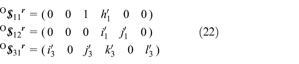
In formula (22), O

The mechanism has 3 DOF. Calculating by reciprocal product operation on the constraints group on the moving platform A3A4, it can be seen that the moving platform A3A4 has 2R1T motion mode at the configuration shown in Figure 8, that is, one moving DOF along the Y axis and two rotation DOF around the rotation pair R4 and around the axis parallel to the Z axis. It can be verified that the 2R1T DOF of the mechanism at the configuration of Figure 8 is not instantaneous.
Rationality analysis of driving pairs selection of the mechanism at 2R1T motion mode configuration
Locking the driving pair R33 does not act the driving force on the link A1A2A4. Locking the rotation pairs R13 and R21 in the kinematic chains that acts the following driving forces on the link A1A2A4:

The constraint screws group acted on the link A1A2A4 by the kinematic chains B1A1, B2A2 and B3A4 are

In formula (24), O

The mechanism has 0 DOF. It can be seen that at the configuration shown in Figure 8, the three driving pairs selected can control the 2R1T motion mode of mechanism.
3R1T DOF configuration
DOF analysis of the mechanism at instantaneous DOF of 3R1T configuration
The link A1A2A4 rotates around the axis of rotation pair R15 from Figures 8 to 9. At this time, the axis

Instantaneous 3R1T DOF configuration of mechanism.
In formula (25), O

The mechanism has 4 DOF. Calculating by reciprocal product operation on the constraints group acted on the moving platform A3A4, it can be seen that the mechanism has three rotation DOF and one moving DOF along the Y axis at the mechanism configuration shown in Figure 9. Because the mechanism configuration shown in Figure 9 is obtained by the rotation of the mechanism configuration in Figure 8 around the rotation axis R15, and the 3 DOF of the mechanism in the configuration shown in Figure 8 are non-instantaneous. Therefore, the 4 DOF of the mechanism in the Figure 9 are instantaneous.
Rationality analysis of driving pairs selection of the mechanism at instantaneous 3R1T DOF configuration
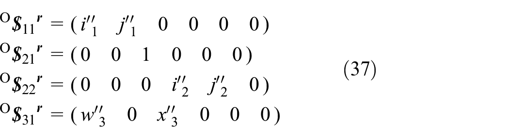
At the mechanism configuration shown in Figure 9, after locking the rotation pair R13, the rotation pair R21, and the rotation pair R33, the driving forces acted on the link A1A2A4 are as follows:
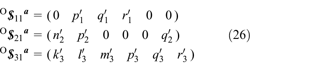
The constraint screws group acted on the link A1A2A4 by the kinematic chains B1A1, B2A2, and B3A4 are as follows:

The screws group consisting of the screws in formulas (26) and (27) shows that seven screws in the screws group are linearly correlated at the instantaneous 3R1T DOF configuration of the mechanism, and there is one redundant constraint in the constraints group acted on the link A1A2A4. The modified Kutzbach-Grübler formula is used to calculate the DOF of mechanism. The mechanism in Figure 9 has 7 links, 8 joints, and 12 single DOF kinematic pairs after driving pairs are locked. The number of redundant constraints is 1. There is no passive DOF.

The mechanism shown in Figure 9 has 1 DOF after locking the driving pairs. It can be seen that at the configuration shown in Figure 9, the three selected driving pairs can not control the mechanism at the instantaneous 3R1T DOF configuration.
Selection of driving pairs of the mechanism at instantaneous 3R1T DOF configuration
According to the analysis results of section “Rationality analysis of driving pairs selection of themechanism at instantaneous 3R1T DOF configuration,” the control of the mechanism at the instantaneous 3R1T DOF configuration can not be realized by locking the rotation pair R13, the rotation pair R21, and the rotation pair R33. Therefore, it is necessary to increase the number of driving pairs. The rotation pair R31 in kinematic chain B3A3 is selected as the auxiliary driving pair. Locking this driving pair that do not act the driving force on the link A1A2A4. When the mechanism has 3R1T instantaneous DOF, the seven screws in the screws group are linearly correlated. The modified Kutzbach-Grübler formula is used to calculate the DOF of the mechanism. The mechanism in Figure 9 has 7 links, 8 joints, and 11 single DOF kinematic pairs after the driving pairs are locked. The number of redundant constraints is 1. There is no passive DOF.

It can be seen that at the configuration of the mechanism shown in Figure 9, using the three driving pairs and the auxiliary driving pair R31 can realize the control of the mechanism at the 3R1T instantaneous DOF configuration.
2R1T DOF configuration
DOF analysis of the mechanism at 2R1T motion mode configuration
The link A1A2A4 rotates from the Figure 9 around the axis


2R1T motion mode configuration of mechanism.
In formula (28), O

The mechanism has 3 DOF. Calculating by reciprocal product operation on the constraints group acted on the moving platform A3A4, it can be seen that the mechanism has two rotation DOF around the axis
Rationality analysis of driving pairs selection of the mechanism at 2R1T motion mode configuration
At the mechanism configuration shown in Figure 10, locking rotation pair R33 does not act the driving screws on the link A1A2A4. The driving screws group acted on the link A1A2A4 by locking the rotation pair R13, the rotation pair R21, and the rotation pair R33 are as follows:
The constraint screws group acted on the link A1A2A4 by the kinematic chains B1A1, B2A2 and B3A4 are

The screws group consisting of the screws (29) and (30) shows that the six screws in the screw group are linearly independent in the 2R1T motion mode configuration shown in mechanism Figure 10. The constraints group imposed on the link A1A2A4 does not have redundant constraint. The DOF of the mechanism is calculated by using the modified Kutzbach-Grübler formula. The mechanism in Figure 10 has 7 links, 8 joints, and 12 single DOF kinematic pairs after the driving pairs are locked. The number of redundant constraints is 0. There is no passive DOF.

Locking the rotation pair R13, R21, and R33 in Figure 10, the mechanism has 0 DOF. It can be seen that at the configuration shown in Figure 10, the three selected driving pairs can realize the control of the mechanism 2R1T motion mode.
3R1T DOF configuration
DOF analysis of the mechanism at instantaneous 3R1T DOF configuration
The moving platform A3A4 moves along the Y axis from the configuration shown in Figure 10 to the configuration shown in Figure 11. At this time, the rotation axis


instantaneous 3R1T DOF configuration of mechanism.
In formula (31), O

The mechanism has 4 DOF. Calculating by reciprocal product operation on the constraints group acted on the moving platform A3A4, it can be seen that the mechanism has three rotation DOF around the point O and one moving DOF along the Y axis at the mechanism configuration shown in Figure 11. Because the mechanism configuration shown in Figure 11 is obtained by the moving of the mechanism configuration in Figure 10 along the Y axis of the fixed coordinate system OXYZ, and the DOF of mechanism in Figure 10 is non-instantaneous, the 4 DOF of mechanism in Figure 11 are instantaneous.
Rationality analysis of driving pairs selection of the mechanism at 3R1T instantaneous DOF configuration
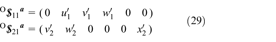
At the mechanism configuration shown in Figure 11, locking rotation pair R33 does not act the driving force on the link A1A2A4. The driving forces group acted on the link A1A2A4 by locking the rotation pair R13, the rotation pair R21, and the rotation pair R33 are as follows:
The constraint screws group acted on the link A1A2A4 by the kinematic chains B1A1, B2A2 and B3A4 are

According to the screws group composed of the screws in formulas (32) and (33), six screws in the screws group are linearly correlated at the 3R1T instantaneous DOF mechanism configuration shown in Figure 11. There is one redundant constraint in the constraints group acted on the link A1A2A4. The DOF of the mechanism is calculated by using the modified Kutzbach-Grübler formula. The mechanism in Figure 11 has 7 links, 8 joints, and 12 single DOF kinematic pairs after locking the driving pairs. The number of redundant constraints is 1. There is no passive DOF.
Locking the rotation pair R13, R21, and R33 in Figure 11, the mechanism has 1 DOF. It can be seen that at the configuration shown in Figure 11, the three selected driving pairs can not realize the control of the mechanism 3R1T motion mode.
Selection of driving pairs of the mechanism at instantaneous 3R1T DOF configuration
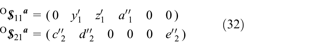
According to the analysis results of section “Rationality analysis of driving pairs selection of themechanism at 3R1T instantaneous DOF configuration,” the control of the mechanism in the instantaneous DOF configuration of 3R1T can not be realized by locking the rotation pair R13, the rotation pair R21, and the rotation pair R33. Therefore, it is necessary to increase the number of driving pairs. The rotation pair R31 is selected as the auxiliary driving pair. Locking this driving pair that acts the driving force as follows on the link A1A2A4.

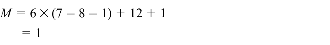
The line vector expressed by the screw in formula (34) is the intersect line of planes of the rotation axes R32 and R34 and the planes of the rotation axes R35 and R4. When the mechanism has 3R1T instantaneous DOF, the seven screws group in (32)–(34) are linearly correlated. the DOF of the mechanism is computed by using the modified Kutzbach-Grübler formula. The mechanism in Figure 11 has 7 links, 8 joints, and 11 single DOF kinematic pairs after locking the driving pairs. The number of redundant constraints is 1. There is no passive DOF.

It can be seen that at the configuration shown in Figure 11, the mechanism can be controlled at the instantaneous DOF configuration of 3R1T by adding the rotation pair R31 of kinematic chain B3A3 as the auxiliary rotation driving pair.
3R DOF configuration
DOF analysis of the mechanism at 3R motion mode configuration
The mechanism moving platform A3A4 rotates around the Z axis from the configuration in Figure 11 to the configuration in Figure 12. The constraint screws group acted on the moving platform A3A4 by the hybrid kinematic chain and kinematic chain B3A3 can be expressed in the fixed coordinate system OXYZ.


3R motion mode configuration of mechanism.
In formula (35), O

The mechanism has 3 DOF. Calculating by reciprocal product operation on the constraints group acted on the moving platform A3A4, it can be seen that the mechanism has three rotation DOF around point O at the mechanism configuration shown in Figure 12. It can be verified that the 3R DOF of the mechanism at the configuration of Figure 12 is not instantaneous.
Rationality analysis of driving pairs selection of the mechanism at 3R motion mode configuration
At the mechanism configuration shown in Figure 12, locking rotation pair R33 does not act the driving force on the link A1A2A4. The driving forces acted on the link A1A2A4 by locking the rotation pair R13, the rotation pair R21, and the rotation pair R33 are as follows:

The constraint screws group acted on the link A1A2A4 by the kinematic chains B1A1, B2A2, and B3A4 are
The screws group consisting of the screws in formulas (36) and (37) shows that the six screws in the screw system are linear independent at the 3R motion mode configuration of the mechanism shown in Figure 12. The constraints group acted on the link A1A2A4 does not have redundant constraint. The DOF of the mechanism is calculated by using the modified Kutzbach-Grübler formula. The mechanism in Figure 12 has 7 links, 8 joints, and 12 single DOF kinematic pairs after the driving pairs are locked. The number of redundant constraints is 0.

Locking the rotation pair R13, R21, and R33 in Figure 12, the mechanism has 0 DOF. It can be seen that at the configuration shown in Figure 12, the three selected driving pairs can realize the control of 3R motion mode of the mechanism.
To sum up, using three driving pairs and one auxiliary driving pair that can make the motion mode of the mechanism transfer from 2T1R to 2R1T or 3R motion mode. In the above 3 DOF motion modes, the mechanism can be controlled by using three driving pairs. When the mechanism is in the 4 DOF configuration of the transformation of the motion mode, besides the three driving pairs, the auxiliary driving pair is also needed to realize the transformation of the motion mode of the mechanism.
2R1T DOF configurations
It is noteworthy that, according to the contents of sections “2R1T DOF configuration” and “2R1T DOF configuration,” the mechanism passes the 2R1T motion mode configuration twice at the process of the changing of the motion mode. According to sections “DOF analysis of the mechanism at 2R1T motion mode configuration” and “Rationality analysis of driving pairs selection of themechanism at 2R1T motion mode configuration,” the DOF of 2R1T motion mode of mechanism are analyzed. At the configuration of two 2R1T motion modes in Figure 13, the moving platform A3A4 has the moving DOF along the Y axis. At the mechanism configuration of Figure 13(a), the moving platform A3A4 has two rotation DOF around the axis

2R1T motion modes configurations of mechanism: (a) 2R1T mode I and (b) 2R1T mode II.
Conclusions
The displacement manifold theory is used to synthesize parallel mechanisms with 2R1T and 2T1R motion modes. The moving platform is connected with the rotation pair in series that constructs a hybrid variable DOF kinematic chain. The new mechanism is composed of the hybrid variable DOF kinematic chain and a variable 5 DOF kinematic chain. The screw theory is used to analyze the mechanism. It is shown that the mechanism has 3R, 2T1R, and two 2R1T motion modes. When analyzing the DOF of the mechanism and the rationality of the selection of the driving pairs, through selecting different link as moving platform, the hybrid kinematic chain can be transformed into series kinematic chain, which will simplify the above analysis process. The mechanism is in a singular configuration of 4-DOF when the motion mode of the mechanism is transferred. Moreover, when the motion mode of the mechanism is transferred, the type or direction of only 1 DOF is changed.
At the general configuration of four motion modes, the mechanism can be controlled by three driving pairs. When the motion mode of the mechanism is transferred, it is necessary to add one auxiliary driving pair to control the mechanism. The instantaneous DOF of the transformed configuration of the mechanism is the combination of two transformed motion modes. When the mechanism transforms its motion mode, the mechanism needs pass the instantaneous 4-DOF of 3R1T or 2R2T configuration. The selected three driving pairs and one auxiliary driving pair can realize the transformation of four motion modes of the mechanism, which is verified by using screw theory.
Hybrid multi-mode kinematic chain combined with multi-mode kinematic chain can be used to design mechanisms with multiple kinematic modes. The assembly geometric relationship of the branch chain can be adjusted according to the target motion mode, so that when multiple motion modes are only transformed between two motion modes, and then the degree of freedom of the mechanism is only increased by 1, so the number of auxiliary drive pair could be minimized. It is feasible to set the path of mechanism motion mode transformation and use one auxiliary driving pair to realize the transformation of more than two motion modes.
Footnotes
Handling Editor: Chenhui Liang
Declaration of conflicting interests
The author(s) declared no potential conflicts of interest with respect to the research, authorship, and/or publication of this article.
Funding
The author(s) disclosed receipt of the following financial support for the research, authorship, and/or publication of this article: This work is supported by The National Natural Science Foundation of China (Grants 51275404).