
Abstract
Aviation cables are widely used in modern avionic devices, and are called the “vessel” of electronic equipment. As the stress environment of modern avionic devices become more complex, the intermittent fault of aviation cables under the vibration stress has received more attention. Aiming at the analysis of the mechanism of intermittent fault and the construction of dynamic models, the relationship between cable damage changes and DC resistance in the absence of vibration stress was analyzed. On this basis, the mechanism of intermittent fault of weak-current cable under vibration stress was analyzed by comprehensively considering the effect of vibration stress. Combined with the test data, the dynamic model of intermittent fault of fully damaged cable and conductor-damaged cable under vibration stress was constructed. Finally, two types of dynamic models were experimentally verified. The results indicated that the dynamic model of the weak-current cable under the vibration stress could well reflect the dynamic characteristics of its intermittent fault and that the performance of cables with different damage states under vibration stress are obviously different.
Introduction
In aviation, it is generally believed that 50% of aircraft system failures reported by pilots are not found in subsequent ground tests, this faulty equipment works normally during the ground test and is put back into use, which might pose a danger to aircraft, crew and passengers and lead to a repeated waste of maintenance resources. 1 This phenomenon, also known as Retest OK (RTOK) and No Fault Found (NFF), has become one of the most time-consuming and expensive maintenance operations.2,3
Intermittent fault is one of the most important reasons for Retest OK. It refers to an equipment that can recover its function without maintenance after the fault occurs. 4 It is difficult to identify and repair, and can only be identified when the fault occurs. When the fault occurs is unpredictable. 5 Therefore, it is difficult for users to eliminate the intermittent fault in time.
Cables are mainly responsible for the transmission of power, command and signal between aircraft systems, and there are quite a few of them. There are more than 100 wire harnesses, more than 500 electrical connectors, and more than 8000 end points in a modern aircraft. 6 The application environment of the cable is complex, and it often needs to work in various environments, so the failure rate increases accordingly.7–9
According to our investigation and analysis, it is found that the study on cable intermittent fault is a relative new research topic, and only a few related studies are found. In terms of cable intermittent fault diagnosis, Hu et al. 10 adopt the method of chaotic signals to diagnose the intermittent fault of cable. At present, there is no research on the mechanism of cable intermittent fault under vibration stress, so this research has high originality. Through investigation and analysis, it is found that among the factors that cause intermittent fault of weak-current cable, environmental factors have a significant impact. 11 Wakil believes that Coupling/interference, design defects, intermittent connections, manufacturing defects, contact degradation are the main causes of intermittent fault. 12 The relaxation or corrosion induced by environmental stress can result in electrical contact degradation and intermittent connections, which contribute to 80% of intermittent faults. 13 Among them, vibration stress is one of the main stress factors that induce intermittent faults. 14
In summary, it is very important to detect and diagnose the intermittent fault of avionics. Cable is an important part of avionics, so research on the mechanism of intermittent faults of cables is representative. Aiming at the problem that the cable has intermittent fault and the mechanism of intermittent fault under vibration stress is not clear, we analyzed the relationship between the damage degree of cable and its DC resistance under the conditions of no vibration stress and vibration stress, so as to reveal the intermittent fault mechanism of cable under vibration stress. Based on the intermittent fault mechanism of cable under vibration stress, the dynamic model of intermittent fault of fully damaged cable and conductor-damaged cable under vibration stress was further constructed, in which the relationship between the degree of cable damage, vibration stress and DC resistance can be described quantitatively, and the dynamic characteristics of cable intermittent fault under vibration stress can be reflected perfectly. This research has laid the foundation for the detection and diagnosis of intermittent cable faults, and has important theoretical significance and engineering value.
Analysis of intermittent fault mechanism of weak-current cable under vibration stress
Analysis of factors inducing faults and cable structure
Due to different use environments and functions, cable structure may differ. Understanding the cable structure is helpful to analyze the mechanism of cable fault and factors inducing fault. In general, the cable can be divided into five parts: conductor, insulation layer, packing layer, shielding layer, and protective layer. Figure 1 shows the structure name of cable with a four-core circular cable as an example.

Cable structure.
The cause of faults is different because the working environment of the cable is different. The deep understanding of the factors inducing the fault of the cable is helpful to analyze the intermittent fault mechanism of the cable. Common factors inducing the fault of the cable include mechanical stress, temperature and humidity, cable head fault, chemical corrosion, etc. Among them, the cable damage caused by vibration stress belongs to the cable fault caused by mechanical stress.
Since there are many types of cables, it is not practical to study each type of cable in isolation. Considering the type of avionics, weak-current cable is selected to explore the intermittent fault mechanism of cable under vibration stress.
Analysis of resistance variation law of weak-current cable in the absence of vibration stress
Both mechanical stress and corrosion stress will cause damage to cable conductor. Conductor damage will lead to changes in the DC resistance of the cable, affecting its function. The cable with damaged conductor can still transmit power and signal through point-contact. The cable with damaged conductor generally does not show fault state, and thus its fault is difficult to be detected. The cable itself can be regarded as DC resistance in the process of conducting electricity. With the gradual fracture of copper wire, the contact area of the cable gradually decreases, resulting in the change of the DC resistance.
The cable with a conduct fault can be divided into three parts, namely initial part, fault part, and terminal part.
As shown in Figure 2,


Classification of fault parts.
where
Assume that the conductive cross-sectional area reduced by each copper conductor fracture is x, then the deformation of the above equation is:

where

In order to investigate the relationship between DC resistance and cable damage, the fracture of copper conductor was tested, thus providing the experimental support for studying the intermittent fault mechanism of the cable.
A pure copper 2-core 4-square cable with a length of 30 cm was used for the experiment, and its resistance was collected through the high-precision acquisition system. A DC power supply was used to provide a power supply with a constant current of 0.1 A to test the resistance of the cable after different copper wires were broken. The acquisition frequency was 1 kHz. The voltage was collected after a copper wire was cut off. And finally, the test data were analyzed. The test scheme is shown in Figure 3.
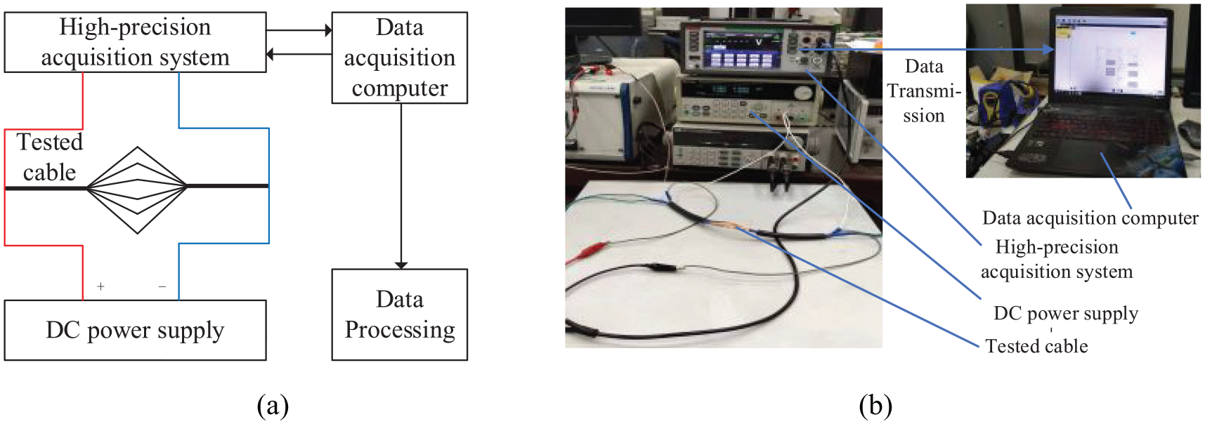
Test scheme: (a) overall structure and (b) equipment connection.
Figure 4 shows the fitting curve and theoretical curve. It can be seen from the figure that the changing trend of the test voltage is consistent with the theoretical curve. After the threshold value of the intermittent fault was set, the relationship between the damage degree of the cable and the intermittent fault could be deduced according to the relationship between the test voltage and the damage degree of the cable. According to the MIL-PRF-32516, the fault resistance was less than 10 Ω for short-term intermittent fault. The fault occurs in the line with signal frequency greater than 10 MHz or sensitive to resistance. 15 As the cable resistance is very small, the intermittent fault of weak-current cable is mostly short-term, whose threshold value is related to the specific application environment and equipment. Therefore, the threshold value was set according to the provisions of GBT3956-2008. The maximum DC resistance of a 4-square copper cable is 4.6, which is equivalent to 1.38 × 10⁻³ of a 30 cm cable. 16 The cable damage process can be divided into three stages by selecting 2 or 10 times of the specified conductor resistance.
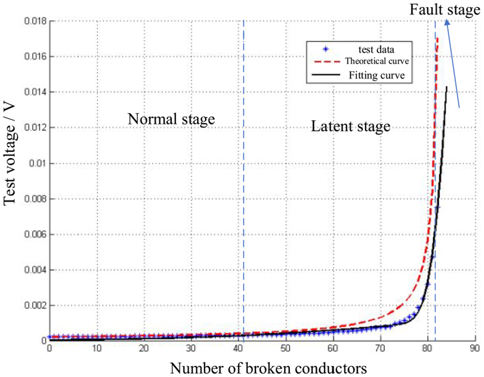
Test voltage.
Normal stage
The fracture number of copper wire is less than 42, accounting for 49.4% of the total number of wires, and the test resistance is less than 2.767 × 10⁻³. At this stage, the test voltage of the cable does not significantly change, the cable resistance is stable, and the function of the cable remains normal.
Latent stage
The fracture number and DC resistance of copper wire are larger than that in normal stage and less than that in fault stage. At this stage, the cable resistance may fluctuate greatly, and intermittent fault may occur.
Fault stage
The fracture number of copper wire is more than 83, accounting for 97.6% of the total number of wires, and the test resistance is greater than 1.518 × 10⁻³. At this stage, the test voltage of the cable increases rapidly, and the probability of intermittent fault of the cable increases obviously.
Analysis of intermittent fault mechanism ofweak-current cable under vibration stress
When the cable conductor is damaged, a part of the broken copper wire still keeps point contact and can still transmit electrical signals. At this time, under the vibration stress, the relative movement occurs between the broken copper wires, and the contact state changes. Then the cable resistance fluctuates, affecting the function of the cable, as shown in Figure 5.
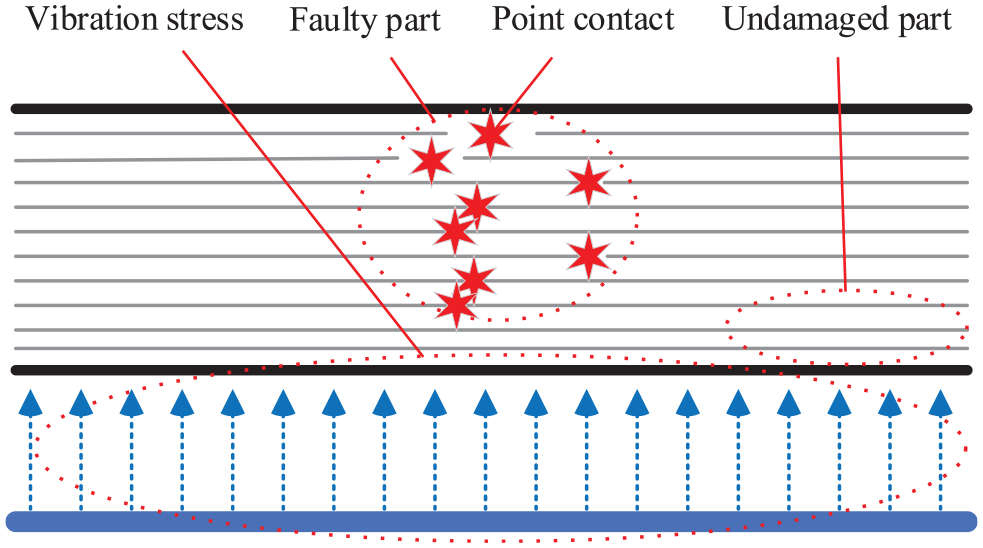
Effect of vibration stress on damaged cable.
Generally speaking, the higher the vibration stress level, the stronger the trend of relative movement of broken copper conductor under vibration stress. The point contact of broken copper conductor under vibration stress is random, so is the change of DC resistance. Therefore, the intermittent fault of the cable occurs randomly. This paper experimentally explored the influence of vibration stress on the DC resistance of the cable.
Four groups of vibration stress environment were designed to collect the DC resistance of the cable, and the DC resistance characteristics were compared and analyzed to directly reflect the effect of vibration stress on the intermittent fault of the cable. The parameters of vibration stress used for the experiment are shown in Table 1.
The vibration stress parameters of the test.

The measurement scheme was designed according to the test requirements for DC resistance acquisition and stress vibration environment, as shown in Figure 6. The four-wire method was used for measurement, and the stress vibration environment was provided by DC-2200 vibration table. A high-precision acquisition system was used to collect data at a sampling rate of 10 kHz, and 100,000 data points were collected for each group. DC stabilized power supply was used to provide a power supply with a constant current of 1 A, and the cable used for the experiment was 30 cm long. The device connection scheme is shown in Figure 7.

Device connection scheme.

Device connection.
A reasonable fault injection method is the primary prerequisite for ensuring the consistency of cable fault mechanism. When the protective layer and insulation layer of the cable are not damaged, they can provide pressure for the broken copper wire, which leads to the change of the mutual movement law of the broken copper wire. In this study, the cable where only conductor is damaged is called conductor-damaged cable while the cable whose protective layer, insulating layer, and conductor are all damaged is called fully damaged cable. In this section, only fully damaged cable was selected to explore the intermittent fault mechanism of the cable under vibration stress. The cable with two fault modes will be analyzed in the third section.
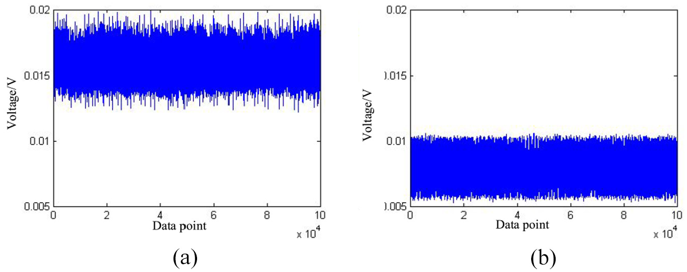
According to Figure 8, the DC resistance of the cable with vibration stress is significantly higher than that of the cable in the absence of vibration stress. The DC resistance of the cable fluctuates more significantly under vibration stress. The effect of acceleration and frequency on the DC resistance of the cable is shown in Figure 9. As can be seen from the figure, the DC resistance of the cable exhibits significantly different characteristics when parameters of vibration stress are different.

Influence of vibration stress on DC resistance of cable: (a) Group 1 (no vibration stress) and (b) Group 2 (vibration stress).
Influence of different vibration stress on DC resistance of cable: (a) Group 3 (30 g 50 Hz) and (b) Group 4 (10 g 100 Hz).
Due to the fluctuation of DC resistance induced by vibration stress in specific equipment, the intermittent fault of cable under vibration stress should have the following characteristics:
If the cable is damaged, intermittent fault is likely to occur, and it can be effectively induced by vibration stress;
The different accelerations and frequencies have different effects on the intermittent fault of the same damaged cable.
To sum up, in order to explore the dynamic characteristics of the intermittent fault of the cable under vibration stress, the dynamic model of the intermittent fault of the cable under the vibration stress was firstly established. Secondly, the established dynamic model was further fit, and finally the quantitative relationship between vibration stress and intermittent fault of cable was established.
Dynamic model of intermittent fault of weak-current cable under vibration stress
Dynamic model construction
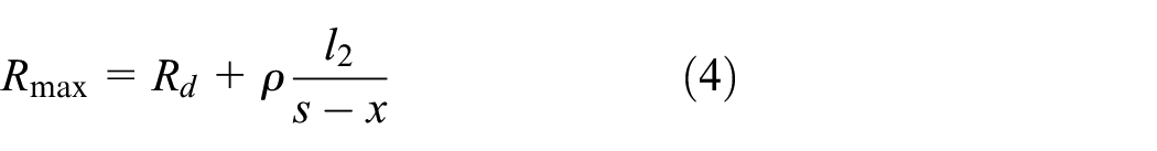
According to the above analysis on the intermittent fault mechanism of the cable under vibration stress, under the influence of vibration stress, the cable DC resistance will fluctuate between the normal DC resistance of the cable and the maximum DC resistance calculated by equation (3). Therefore, the maximum DC resistance of the cable under vibration stress is
As shown in formulas (2) and (3),

If

where
When the damage state is x, the DC resistance of the cable should fluctuate between

where
In order to explore the specific relationship between random factor
DC resistance acquisition test
The test requirements were consistent with the above, so the test equipment and connection method were the same as those in Figure 7. In order to comprehensively analyze the different characteristics of cable faults under the two kinds of damage conditions, tests were carried out for different damage conditions.
In this test, acceleration
Parameter setting of test vibration stress.
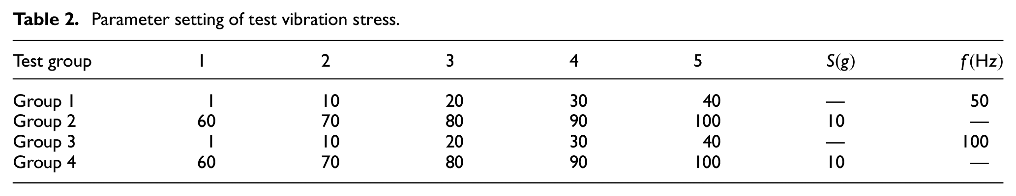
Six decimal places of test data were retained during data processing. According to the frequency corresponding to each resistance value, the probability of random factor

Data statistics process.
Parameter fitting of dynamic model
In the process of fitting the dynamic model, the input is the probability frequency of a value, and the expected output is the function of the relationship between vibration stress parameters and the random factor

Fitting process.
Parameter fitting of process A
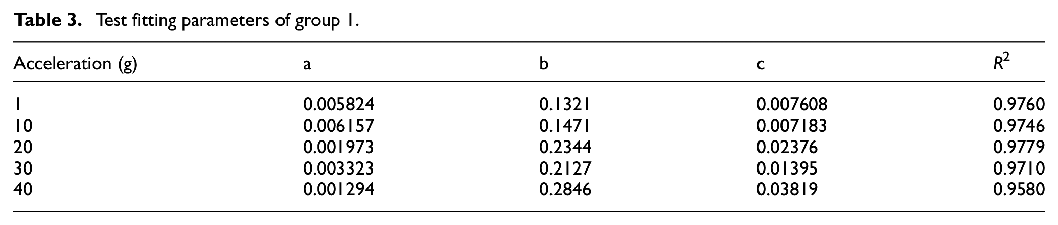
After fitting the test data of each group, it was found that the fitting relationship could be expressed by
Test fitting parameters of group 1.
Test fitting parameters of group 2.

Test fitting parameters of group 3.

Test fitting parameters of group 4.

The second fitting of parameter a
In order to express the change relationship between the fitting parameter a and the vibration stress parameter conveniently, the parameter a in the Tables 3 to 6 was fitted by SPSS, and the fitting results (as shown in Table 7) were drawn in the same figure by MATLAB. The second fitting result of parameter a was shown in Figure 12. The scatter plot represents the parameter value of the first fitting function, and the solid line represents the second fitting function. Combined with Table 7 and Figure 12, the fitting of parameter a was analyzed, and it was found that the four groups of tests conformed to the linear equation. The second fitting slope of Group 2 was much smaller than that of Group 1 (about 1/100). The second fitting slope of Group 4 was also smaller than that of Group 3 (about 1/10). In the case of vibration stress parameter, it is believed that the parameter is only determined by the acceleration and does not change with the vibration frequency. Therefore, From the second fitting results of parameter a in group (1) and group (2) (see Table 7 for the second fitting results of parameter a), the parameter a of a fully damaged cable is:

The second fitting of parameter a.


The second fitting of parameter a.
And the parameter a of a conductor-damaged cable is

where S is the vibration acceleration level, and the unit for S is g.
The second fitting of parameter b
The second fitting results of parameter b in the Tables 3 to 6 were shown in Table 8 and plotted in Figure 13. Combined with Table 8 and Figure 13, the second fitting of parameter b was analyzed. According to the fitting results of tests on acceleration and frequency, the fitting slope of Group 2 was far smaller than that of Group 1 (about 1/100). Therefore, the value of parameter b of a fully damaged cable under vibration stress is considered to be determined by acceleration, and can be expressed as:

The second fitting of parameter b.


The second fitting of parameter b.
When the sample cable is a conductor-damaged cable, the parameter
The form of multivariate equation could be estimated based on the fitting results of univariate equation in Table 9. The multivariate equation was successively fit, and the optimal fitting result was selected by comparing the goodness of fit. The form of multivariate equation and fitting results are shown in Table 9. Therefore, when the sample cable is a conductor-damaged cable, the value of parameter b is:

The fitting of multivariate equation.
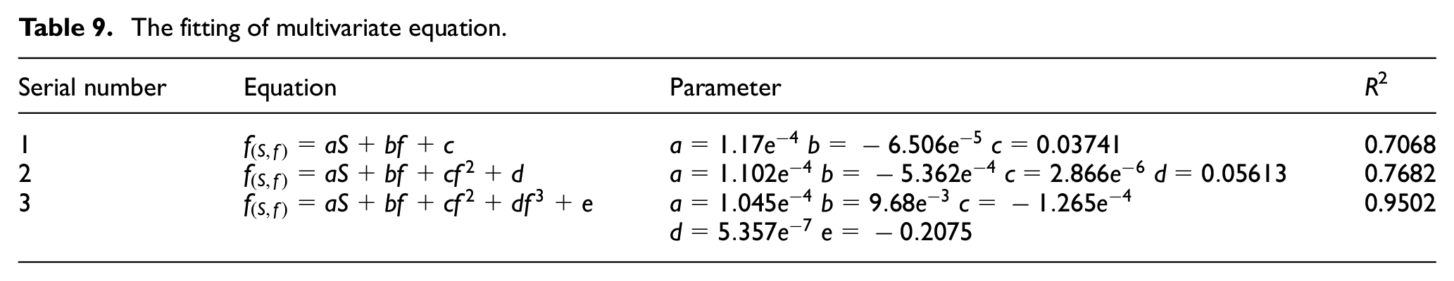
where S is the magnitude of vibration acceleration (g), f is vibration frequency (Hz). Figure 14 shows the fitting diagram of the optimal fitting scheme.

The multivariate fitting of parameter.
The second fitting of parameter c
The second fitting results of parameter c in the Tables 3 to 6 were shown in Table 10 and plotted in Figure 15. The second fitting results of parameter c were analyzed according to Table 10 and Figure 15. The fitting function

The second fitting of parameter c.


The second fitting of parameter c.
When the sample cable is a conductor-damaged cable, the value of parameter c is

Inspection and analysis of dynamic model
The fully damaged cable
According to the above analysis and fitting results of DC resistance acquisition of the fully damaged cable, the relationship between parameters a, b, c and vibration stress parameters could be obtained. Furthermore, the dynamic model of the intermittent fault of the cable could be described as follows:

where S is the magnitude of vibration acceleration (g), f is vibration frequency (Hz).
In order to test the dynamic model, a group of vibration stress parameters were designed to calculate the theoretical values, and the validity of the dynamic model was verified by comparing with the test data. Given the vibration stress parameters,
The design of vibration parameters.

The DC resistance acquisition of the cable under the same vibration stress parameters was tested. The organization scheme, acquisition method and test equipment connection were the same as what are mentioned earlier. The test data under the vibration stress environment were statistically analyzed. The parameters
The fitting results.

According to Tables 11 and 12, the difference between the fitting value and the predicted value could be obtained (
The fitting results.
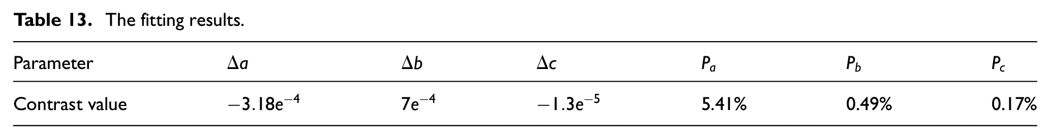
It can be seen from Table 13 that the difference between the theoretical value and the fitting value is very small. The percentage of the difference in the fitting values was less than 6%, with a minimum value of 0.17%. The above table can fully verify the dynamic model of intermittent fault of the cable under vibration stress. The model can relate the vibration stress and damage degree to the DC resistance of the cable and accurately express the changing rule of the DC resistance of the cable after it is damaged.
The conductor-damaged cable
According to the fitting results of conductor-damaged cable test, the dynamic model of the intermittent fault of the conductor-damaged cable could be obtained by substituting the fitting function into the dynamic model, as shown in equation (15).

To verify the dynamic model, the vibration stress parameters were set, as shown in Table 14. According to the dynamic model, the parameters
The design of vibration parameters.

The fitting results.

According to the theoretical value and fitting value in the above table, the difference of each parameter and the percentage of the difference value in the test fitting value were calculated, as shown in Table 16.
The fitting results.

It can be seen from the above table that the difference between the theoretical value and the fitting value of conductor-damaged cable is very small, with a maximum value of 4.05% and a minimum value of 4.05‰. Therefore, the model accurately represents the relationship between vibration stress, damage degree of the cable, and DC resistance.
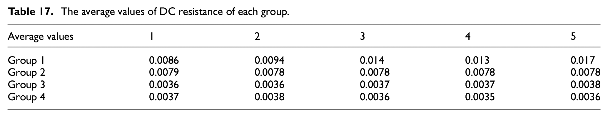
The average DC resistance of each group in the third section of this paper is shown in Table 17. It can be seen from the table that the DC resistance of the fully damaged cable is more likely to change with vibration stress. And the DC resistance of the conductor-damaged cable is obviously smaller than that of the fully damaged cable, implying that that the DC resistance of the fully damaged cable is more likely to reach the threshold of intermittent fault under vibration stress. Under the influence of vibration stress, the conductor-damaged cable is not likely to demonstrate the characteristics of the fault, but with a relatively stable resistance.
The average values of DC resistance of each group.
However, the possibility of intermittent failure is determined by the damage of the conductor and the internal damage of the cable. In order to study the fault response of the conductor-damaged cable, the bending test of cable was carried out. The cable after fault injection was selected for bending test, and its DC resistance test scheme was consistent with the previous test scheme. The bending method is shown in Figure 16. Bending upward and returning to the original state is regarded as one-time bending. The bending test was repeated three times, and the DC resistance test results were obtained, as shown in Figure 17.

The bending method.

The response of faulty cable DC resistance to bending.
As shown in Figure 17, the response of the DC resistance of the cable to the third bending can be clearly distinguished. In the bending process, the DC resistance of the cable fluctuated greatly. At the end of bending, the DC resistance of the cable recovered to the normal value and remained stable. The test directly reflects the sudden change of the DC resistance of the conductor-damaged cable.
Conclusion
To sum up, in order to solve the intermittent fault problem of weak-current cable, the mechanism of intermittent fault of low-voltage cable under vibration stress is studied in this paper. The main conclusions of the thesis are summarized as follows:
The mechanism of cable intermittent fault under vibration stress was analyzed by combining theory with test. It is believed that the damage of cable conductor leads to the change of effective contact area of cable conductor. Under the influence of vibration stress, the damaged conductor changes between the point contact state and the fracture state, resulting in the fluctuation of the DC resistance of the cable. When the DC resistance of the cable reaches a certain threshold, the intermittent fault occurs.
The dynamic model of intermittent fault of weak-current cable under vibration stress was constructed. The results show that the dynamic model can better reflect the dynamic characteristics of intermittent fault of weak-current cable under vibration stress, and can better describe the relationship among damage degree of the cable, vibration stress, and DC resistance.
Based on the dynamic model, the intermittent fault characteristics of fully damaged cables and conductor-damaged cables were analyzed. The analysis results show that the DC resistance of conductor-damaged cables under vibration stress is relatively stable, and generally intermittent fault will not occur. Therefore, intermittent fault is likely to occur in the conductor-damaged cables only under bending stress.
Frankly speaking, there are still some deficiencies in this paper. For example, in the study of fully damaged cable dynamic model, the influence of frequency was ignored, which led to insufficient model accuracy. Improving the accuracy of dynamic model will be the next research direction. Therefore, in the next research, the stress test with smaller gradient should be carried out, and the coupling analysis of vibration acceleration and vibration frequency should be carried out to obtain a multivariate fitting equation, which can further improve the accuracy of the model.
Footnotes
Handling Editor: Chenhui Liang
Declaration of conflicting interests
The author(s) declared no potential conflicts of interest with respect to the research, authorship, and/or publication of this article.
Funding
The author(s) disclosed receipt of the following financial support for the research, authorship, and/or publication of this article: This work was supported by the Basic Strengthening Program under Grant 2019-JCJQ-ZD-153-03.