
Abstract
The evolution of contact performance of electrical connectors, as an expression of service performance, played a significant role in various electronic equipment or system. However, very few methods had been used to detect the evolution of contact performance effectively and accurately. Hence, in this research, reliability accelerated testing was conducted to investigate the evolution of contact performance of electrical connectors. To detect the evolution of contact performance, contact resistance and friction and wear of the connector were measured using a DC resistance tester and an electron microscope respectively. Also, the effect of external conditions such as ambient temperature, mating speed, mating cycles was statistically investigated, and evolution curves were developed for contact resistance and abrasion loss. The obtained results revealed the temperature and mating speed affected the contact performance of electrical connectors. The increment of temperature reduced the shear strength of material and increased the thickness of oxide film. Increased mating speed greatly increased the probability of fracture of micro-protrusion due to collision, the wear form of connector had realized transition from low-speed adhesive wear to high-speed peeling wear. In addition, when the connector was mated about 3000 cycles, the contact performance of the connector would be greatly decreased.
Keywords
Introduction
The electrical connector was one of the basic electrical components, which was a major area of interest within the field of aerospace, industrial robots, electronic communications, and other fields. Its contact performance affected the reliability of the entire system. However, a large number of data showed that the contact failure of electrical connectors was the main failure mode in the failure of electronic equipment, accounting for about 45.1% of the total failure.1,2 The electrical connector had been recognized as one of the four components with poor reliability. 3 Therefore, it was necessary to detect the evolution of contact performance of electrical connectors during the service process and predict the service life of electrical connectors. In this regard, the male end and the female end of the industrial robot connector could be quickly mated to observe its evolution of contact performance by the accelerated test method. Meanwhile, the failure mechanism was explored from two angles: oxidation corrosion and friction and wear of metals, and the corresponding suppression methods were searched.
In recent years, researchers had shown an increased interest in the reliability of electrical connectors during the mating process, Stefan 4 believed that friction and wear were the main reasons for the failure of electrical connectors. The research contents of electrical connector testing were surface roughness and oxidation corrosion normally. For example, Carvou et al. 5 simulated its mating test in the working state and quantified the contact resistance in its contact area by studying the power connector. Ksiazkiewicz et al. 6 studied the variation of electric contact resistance of low-voltage relays affected by fault current, and found the flow of significant current through electric contacts may influence the contact surface and thus the value of the electric contact resistance (ECR). Kim et al. 7 studied the influence of surface roughness, oxidation, and pollution on the variation of contact resistance of electrical connectors. The experimental results showed that pollution had the most significant influence on the variation of contact resistance. Francisco et al. 8 studied the relationship between contact surface morphology and contact resistance, the number of contact spots between contact pieces increased, the contact resistance decreased. Kong and Swingler 9 and Liu et al. 10 found that the more serious wear on the contact surface of electrical connectors, the greater the friction force, and contact resistance. Zhang et al. 11 reported that the silver and aluminum electrodes are in contact with each other to form a galvanic cell, which was an important reason for the contact resistance of the battery. Noel et al. 12 investigated the fretting wear of nickel coatings for electrical contacts application in dry and lubricated conditions, the plating conditions are shown to have a large effect on the microstructure, composition of the nickel coatings. All of the above researches considered friction and wear as the main factors affecting contact resistance and researched the influence of contact resistance with mating distance. According to the existing literature research, there were few studies discussed the friction and wear of the connectors as well as the various characteristics of contact resistance in different operating conditions.
To more accurately analyze the variation characteristic of contact resistance, many scholars found that changing operating conditions could also affect the contact resistance, Choi et al. 13 measured the contact resistance of the connector and found that with the increase of the electrical connector’s working temperature, the size of the electrical connector increased, the contact resistance decreased. Guarino et al. 14 researched the influence of thermal contact resistance of aluminum foams in forced convection. Han et al. 15 studied the properties of anisotropic insulation materials and revealed that the thermal conductivity and thermal contact conductance increased as temperature and pressure increased. Capelli et al. 16 analyzed the dependence of contact resistance on temperature through experiments, finding that the contact resistance increased with the increase of temperature, and there was almost a linear relationship between contact resistance and temperature. Sung et al. 17 investigated the effect of displacement and humidity on contact resistance of copper electrical contacts, under the partial slip regime the contact failure was susceptible to the displacement and moisture effectively increased contact stability, which was pronounced at smaller displacements. Park et al. 18 found the fretting corrosion degradation of tin-coated contacts occurred much faster at higher currents by studying the influence of current load on fretting of electrical contacts because it generated more accumulation of oxide wear debris at the contact zone. Qiu et al. 19 found the contact resistance of metal contacts was closely related to the presence of heterogeneous hydrocarbon films on the contact surface. Jackson et al. 20 believed that the electrical contact resistance increased measurably with reciprocating movement. They also showed that the spring of the connector was plastically deformed due to being mated many cycles. The multi-scale rough surface contact model was used to find that the plastic deformation led to the reduction of the contact force of the connector, thus increased the contact resistance. Ren et al. 21 found in the study of fretting wear that fretting amplitude and fretting speed were the key factors to affect the contact resistance of the contact point: certain fretting amplitude was the prerequisite to make the gold-plated layer fall off. The raise of fretting speed led to the excessive relative motion speed between the contacts. Shahzad et al. 22 studied the effects of different ion irradiation on the contact resistance of PD/graphene contacts and found ion-induced defects served an excellent purpose to reduce the contact resistance. The above studies show that the influence of changing ambient temperature on contact resistance in fretting friction. Because the connector was mated multiple cycles in actual use, which would reduce its contact performance. It is important to judge the evolution of contact performance of the electrical connector with the increase of mating cycles.
To consider the influence of mating times on contact resistance, Luo et al. 23 proposed an reliability accelerated testing method for electrical connectors under temperature cycling conditions. The result showed that as the temperature cycling times increased, the deformation of electrical connector contacts increased. When the deformation increased to a certain value, the contact pressure would decrease, leading to the failure of electrical connectors. Luo et al. 24 studied the electrical connector fault diagnosis under a high-temperature environment based on constant stress accelerated life test and found that as the temperature stress increased, the contact resistance value gradually increased, but the increment was not large. Ren et al. 25 selected randomly vibration and current stress as acceleration factors to affect the mating-in life of electrical connectors according to circular electrical connectors. Statistical analysis results obtained the characteristics of electrical connectors under the action of vibration and current stress. The above studies involved acceleration test methods, in which the acceleration factor was mainly temperature. However, the research on the influence of the speed factor and the coupling was less.
According to the above-mentioned literature, most of the researchers had investigated the effect of changing the working environment on the contact performance of electrical connectors. Very few studies detected the evolution of contact performance by reliability accelerated testing, and in these studies, only one acceleration factor was selected for the experiment such as ambient temperature, humidity, mating cycles. According to the current literature survey analysis, there was little work concerning the variation of material physics due to the ambient temperature, mating speed, and friction and wear affect the evolution of contact performance. Hence, the main goal of this study was to investigate the influence of the ambient temperature and the mating speed on the contact performance by exploring the mechanism of metal oxidation corrosion and friction and wear. The evolution curve of contact resistance was obtained, which had guidance on the use environment, the cycles of mating, and the method of use of electrical connectors. The connectors of an industrial robot and electrical equipment widely used were selected as the research object while an electrical connector test system was designed for testing. To detect the evolution of contact performance, electrical connectors were studied in different working conditions: environment temperature, mating speed, and multi-factor coupling conditions under different mating cycles, the changing rule of the contact resistance. The rule could detect that the evolution of contact performance of the electrical connector with the increase of mating cycles and reflected the variation characteristics of the connector in a complex working environment.
Experimental set-up
Experiment system
The connector (CDSM-0.75) commonly used in industrial robots and electrical equipment included the pin and the jack, the pin (diameter: 2.4 mm, length: 26.4 mm) and the jack (diameter: 3 mm, length: 24.2 mm) were selected as the research object. The material of the connector was tin bronze (Qsn4-3) with a silver layer of 3–4 µm. The silver layer could effectively reduce the contact resistance and improve the friction and the wear-resistance property of the electrical contact parts. The reliability acceleration test system is as shown in Figure 1. The mechanical movement module adopted the high-speed linear sliding table with a travel of 300 mm and a precision of 0.1 mm. A double linear sliding table was guaranteed to be parallel by a dial indicator. The pin and the jack were fixed with the male and female ends respectively, the male end was installed on the motion seat and the female end was installed on the fretting seat, the motion seat, and the fretting seat was respectively mounted on the guide rail by sliding blocks. Before each experiment, the male and female ends were adjusted to ensure that the connectors could be mated concentrically. A photoelectric sensor was used to ensure consistent insertion amount and the piezoelectric sensor was used to collect the mating force. The mating movement of the male end and the female end was realized by controlling the stepper motor to drive the double linear sliding table. The pulse frequency of the stepper motor was adjusted to change the mating speed, 9, 18, 27 mm/s. The reliability acceleration test was performed at three different temperatures, 20°C, 40°C, 60°C. To ensure the experimental temperature, the fan heater (CSH8) and the thermocouple were used to heat the temperature control box. The output signal of the thermocouple is collected by the temperature controller (REX-C100), the thermostatic heating of the temperature control box is carried out by PID control.
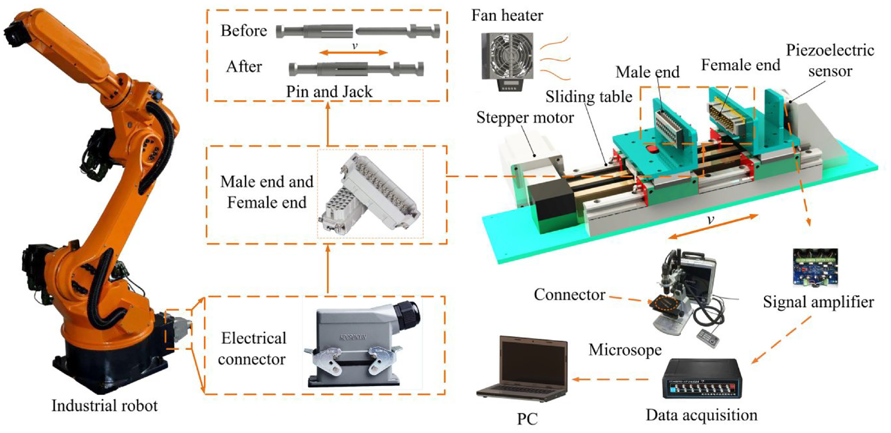
Diagram of the reliability acceleration testing system.
The data acquisition unit consisted of a data acquisition instrument, a DC resistance tester, an electronic balance, and a high-speed digital microscope. The (DYMH-105) output voltage of the piezoelectric sensor was 0–10 V, the measurement range was 0–20 N, the accuracy was 2 mV/V, the frequency response was 20 Hz, and the operating temperature range was −20 to 100°C. The data acquisition instrument (uT3408FRS-ICP) collected test data (sampling frequency 10,240 Hz, trigger method: rising edge detection). The contact resistance of connectors was measured by kelvin four-wire measurement method, the range of measurement was 0.1 μΩ–3 mΩ, the accuracy was 0.02% Full·Scale. The quality of the connector was measured by an electronic balance (YP6102) with a division value of 0.01 g and a maximum scale of 610 g. The high-speed microscope was a keens-type high-speed micrograph (Keyence VHX-700F, the type of lens was VH-z, maximum magnification was 5000 times) used to observe and analyzed the surface wear of connector pins.
Experimental management
To explore the influence of ambient temperature, mating speed, and mating cycles on the contact performance of connectors, nine groups of tests and eight pairs of connectors for each group were set to ensure the accuracy and reliability of the test data. The specific experimental parameters were shown in Table 1. Under the temperature factor, three levels were selected: 20°C, 40°C, and 60°C, in which, 20°C was ambient temperature; 40°C was the ambient temperature in summer. Since people could not work for a long time, industrial robots were usually used to replace human workers to set a high-temperature of 60°C. To simulate the normal use of the mating speed, the speed factor was divided into three levels as low, medium, and high. Forward insertion and reverse extraction of the connectors were considered as one cycle of the mating process. According to the investigation, the electrical performance of the general connector would be greatly reduced after 4000 mating cycles. In this test, several test gradients were added below 4000 cycles to explore the variation of contact performance of the connector. According to the maximum life of the connector for 3 years, 10 cycles of mating were calculated every day, with a total of 10,950 mating cycles. Therefore, the maximum test of 10,000 mating cycles was set. During the process of data collection, the values of mating-in quality, mating force, and contact resistance were collected and measured many times, the average value was taken as the test result to reduce the experimental error.
Experimental condition.

Results and discussions
Influence of ambient temperature on contact resistance
To investigate the influence of ambient temperature on the contact resistance, the contact resistance is measured under different working environments in which the ambient temperature is varying while the mating speed is kept constant at its low level, corresponding to the order 1, 4, and 7 in Table 1. According to the experimental arrangement, six cycles are selected as test cycles. To obtain data on each test cycle, the contact resistance of the connector is measured multiple times and averaged when the pin and jack are fully inserted to reduce the experimental error. To get the various trends of contact resistance, the relationship between mating force and contact resistance has been studied in depth. It is found that the smaller the mating force, the greater the contact resistance. The changing trend of contact resistance is observed by monitoring the mating force because the mating force is recorded in real-time by a piezoelectric sensor, the contact resistance is measured only in six test cycles. Consequently, the six test cycles at each temperature are plotted as curves to obtain Figure 2. Figure 2(a) and (b) respectively show the variation curves of contact resistance and mating force with the number of mating cycles at different ambient temperatures.

Contact resistance and mating force at different temperatures: (a) contact resistance and (b) mating force.
As shown in Figure 2(a), after 10,000 mating cycles, the maximum variation of contact resistance is at the ambient temperature of 60°C, it increased from 0.34 to 0.57 mΩ, increasing by 0.23 mΩ. The minimal variation of contact resistance is at the ambient temperature of 20°C, it increased from 0.35 to 0.51 mΩ, increasing by 0.16 mΩ. As the cycles of mating increases, the contact resistance has a rising trend and the trend is different at different temperatures. The variation of contact resistance caused by temperature is mainly concentrated in 0–3000 mating cycles. A rapid variation of the variation of contact resistance occurs in 0–500 mating cycles at 60°C. When the ambient temperature at 40°C, this phenomenon occurs in 1000–3000 mating cycles. Increased temperature accelerates the evolution process. Similar results can be found in the literature for mechanical behavior and fatigue life estimation on the fretting wear of the electrical connector. As shown in Figure 2(b), the greatest values of insertion force and extraction force occur in 500 mating cycles and the insertion force is always greater than the extraction force. As the cycles of mating increases, the insertion and extraction force both show a tendency of increasing first and then decreasing, and the decreasing tendency becomes more and more gentle.
The force between the contact surfaces of the connector consists of two parts during the mating process, contact diagram of the connector as shown in Figure 3.
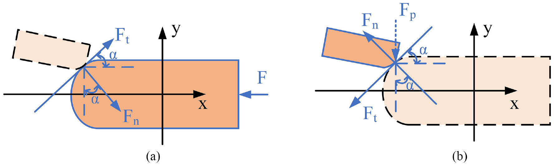
Contact diagram of the connector: (a) force analysis of the pin and (b) force analysis of the jack.
According to Figure 3, Ft is friction, Fn is normal contact pressure, µ is coefficient of friction between contact surfaces, Ft = µFn, α is the angle between friction and the axis of the connector. The angle(α) of the electrical connector does not change in the mating process. As shown in Figure 3(a), the mechanical balance of the connector is achieved under the action of three forces. According to mechanical analysis, the relationship between the contact pressure and the mating force of the jack due to elastic deformation could be obtained by equation (1).
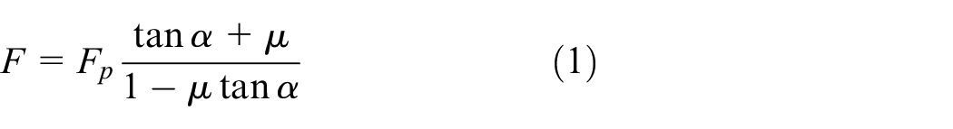
According to equation (1), the variation of contact pressure is observed by the mating force curve due to the contact pressure is difficult to be obtained. Also, the contact pressure affects the variation of contact resistance, and the calculation of contact resistance is shown in equation (2).
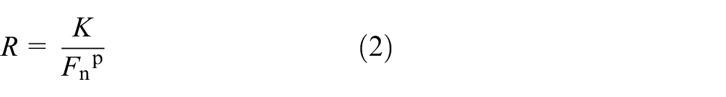
R is the contact resistance of the interface, P is contact pressure, K and p are coefficients. The material of the connector softens due to the increment of temperature, which causes the decrement of contact pressure. Decreased contact pressure leading to a decrease in the contact area, which results in the increment of contact resistance. In addition, it is found that the formation of oxide film changes the material physics performance with the increase in temperature, which leads to the variation of contact resistance. According to the results of Huang et al. 26 , with the increase of the number of fretting cycles, the contact resistance increases, and the contact area decreases accordingly. Also Kehong et al. 27 provides qualitative analyses of the impacts of temperature stress on electrical contacts, the results show that the more extreme the temperature, the more obvious their influences for contact resistance.
The contact resistance consists of shrinkage resistance, matrix resistance, and film resistance. From the micro-physical point of view, the actual contact surface should be rough and give rise to the microscopic peaks. The current can only flow through two peaks that are in contact with each other and shrinks sharply at the contact spots, the resistance is defined as shrinkage resistance. The matrix resistance is caused by the resistivity of the material, and the resistivity is affected by temperature. The main source of membrane resistance is the surface oxidation of metal materials. The oxide film reduces the ability of current to penetrate the film layer, leading to the increment of contact resistance, and the variation of temperature changes the film thickness.
28
At the first 3000 mating cycles, the variation of contact resistance is mainly caused by temperature. After 3000 mating cycles, the rate of change of contact resistance at different temperatures tends to be consistent, and friction and wear are the main factors causing the change of contact resistance. The increment of contact resistance before 500 mating cycles is higher than that of 500–10,000 mating cycles. This is because copper is more active than silver, and it is very easy to form an oxide film in the air. Silver plating on the copper surface can effectively reduce the contact resistance. When the silver coating is broken and the base copper is exposed to the air, it takes only 2–3 min to form an oxide film. According to Gen et al.
29
, the formation process of oxides is
Stage I: 0–500 mating cycles. At the beginning of mating, a small number of cracks appear in the silver-plated layer, and the copper substrate is gradually exposed (electrical conductivity of silver is greater than copper), the oxygen in the environment comes into contact with the base copper along these channels, an electrochemical and chemical reaction occur to produce Cu2O,30–32 oxidative corrosion is shown in Figure 4. Cracks in the silver-plated layer of the connector can easily absorb water vapor suspended in the atmosphere and form an electrolyte. Since the standard electrode potential of silver is 1.77 V and the standard electrode potential of the base copper is 0.34 V, a large potential difference can form galvanic between the surface silver and the base copper, an electrochemical reaction is occurred. 33 The base copper with a low electrode potential is the anode, a reduction reaction has occurred and electrons are lost; the silver with a high electrode potential is used as the cathode, an oxidation reaction has occurred and the oxygen adsorbed on the surface is ionized by electrons. Due to the higher diffusion activation energy of copper, copper ions migrate to the surface of the silver-plated layer. Cu+ and OH− generate CuOH, the generated CuOH is hydrolyzed to generate Cu2O. Also the redox reaction on the surface of the connector occurs simultaneously. The substrate copper undergoes a reduction reaction, electrons are lost. The oxidation occurs in the cracks on the silver-plated layer surface, thus, electrons are got. Copper ions rapidly migrate to the surface and the oxygen ions are combined to form Cu2O. The increment of temperature accelerates the diffusion rate of ions, which accelerates the reaction, resulting in a rapid increase in contact resistance in stage I.
Stage II: 500–3000 mating cycles. As the number of mating cycles increases, the silver plating is worn away and the copper substrate is completely exposed to the air. The Cu2O produced in stage I is fully contacted with oxygen in the air, and a large amount of CuO is generated under the catalysis of temperature. The higher the temperature, the faster the rate of CuO production. What’s more, the conductivity of CuO is better than that of Cu2O and the density of CuO is lower than that of copper, which leads to the reduction of the number of points on the contact surface. Therefore, in stage II, the contact resistance continues to increase but the trend of the increase becomes gradual.
Stage III: 3000–10,000 mating cycles. After multiple mating cycles, plastic deformation occurs on the surface with a large amount of heat is generated; the elastic modulus decreases; the rough peak is completely worn; the contact pressure decreases and stabilizes gradually. Those lead to a continuously increasing trend in the contact area at this stage, and the reducing rate becomes gradual. Therefore, the contact resistance at this stage continues to increase slowly. In the first two stages, the temperature has a greater impact on contact resistance than friction and wear. The increment of temperature accelerates the diffusion rate of Cu+ which accelerates the formation rate of the oxide film, resulting in poor contact performance.
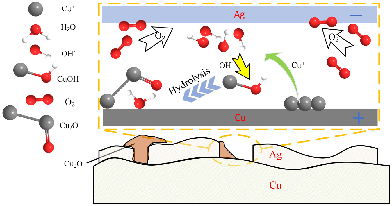
Schematic of oxidative corrosion on contact surfaces.
Influence of mating speed on contact resistance
From the influence of ambient temperature on contact resistance, it can be known that the ambient temperature changes the thickness of the film layer on the surface and contact pressure of connectors. The main cycle of influence on contact resistance is the first 3000 mating cycles. To explain the influence of different mating speeds on contact resistance, the variations of the contact resistance and the abrasion loss are plotted when the ambient temperature is 20°C and the connector has been mated 3000 cycles at different speeds. The wear surface morphology is observed by a microscope. The contact resistance, abrasion loss and wear surface of the connector are shown in Figure 5. To prevent the leftover debris from affecting the weighing results of the connector after mating, the connectors at different speeds are placed in a 99.7% concentration of absolute ethanol for 20 min. To obtain the abrasion loss of the connector, after ultrasonic cleaning, anhydrous ethanol on the surface is dried and then an electronic balance is used to measure the variation of mass.

Contact resistance, abrasion loss, and wear surface of the connector at different speeds: (a) contact resistance and (b) wear surface.
As can be seen from Figure 5, the least value of contact resistance is 0.382 mΩ at the mating speed is 18 mm/s, at the same time, the amount of connector wear is minimal. The minimal value of abrasion loss is 3.8 mg and the surface of the connector is relatively smooth with only a few narrow furrows. The greatest value of contact resistance is 0.441 mΩ at the mating speed is 27 mm/s and the amount of connector wear is maximum. The maximum value is 5.3 mg and a large number of pits and wide furrows appear on the surface of the connector, which makes the surface very rough. The contact resistance and abrasion loss of connector firstly decrease and then increase with the increase of mating speed. When the mating speed increases from 9 to 18 mm/s, the contact resistance decreases from 0.393 to 0.382 mΩ, which decreases by 0.01 mΩ; when the mating speed increases from 18 to 27 mm/s, the contact resistance changes from 0.382 increased to 0.441 mΩ, which increases by 0.059 mΩ.
According to the results obtained, it is found that the contact area change of the connector affects the contact resistance. When the connector is relatively slipped, the micro-protrusions on the frictional surface contact each other under the effect of the contact pressure. According to the theory of adhesive friction, 34 the material at the contact interface is worn due to the adhesion and furrow during the relative sliding process, which leads to the appearance of material transfer and the generation of debris. Increased the mating speed causing friction and wear, which deteriorates the material physics performance, changing the shearing force required to damage the surface during the friction process. The contact area between the friction surfaces changes, which leads to an increment of contact resistance of the connector. The abrasive debris at two speeds is evenly distributed on graph paper with a minimum scale of 1 × 1 mm. Taking the light spot of the microscope as the origin, two squares with the same X-axis and Y-axis coordinates are selected for observation. The ratio of large particles of abrasive debris at high speed is generally greater than that at low speed through the microscope.
Figure 6 shows the schematic diagram of the form of wear. On the friction surface of the contact point, the micro bumps bite each other. When the mating speed is 9 mm/s, less heat is generated by friction due to the slow mating speed, and friction oxides are difficult to generate. The form of collision wear between the rough peaks is mainly adhesive wear, which leads to the materials transfer and produces a small amount of debris. Some of which are transferred out of the contact area during the mating process; some are located between the two surfaces and micro-rolled, so that there is compound friction of sliding and rolling on the contact surface. There are some left are embedded on the contact surface due to the contact pressure and heat of friction. The smooth groove that plays a guiding role is generated on the contact surface due to the reciprocating movement of the pin, and the wear on the low-speed connector is small. When the mating speed increases to 18 mm/s, more heat is generated due to friction, and the oxides friction increases. when the wear surface is covered by a large area of friction oxide, which enters the stage of slight oxidation wear, and the abrasion loss is extremely low. 35 Therefore, the abrasion loss and contact resistance of the connector do not change significantly at that speed. As the mating speed of the electrical connector increases to 27 mm/s, the effect of adhesive wear on the surface of the electrical connector decreases, and more severe collisions occur between the rough peaks, which leads to cracks at the bottom of the rough peaks. After the connector has been multiple mating cycles, the surface of rough peaks break and appear pits eventually. The form of wear gradually transfers to peeling wear, and large debris is formed on the surface, forming a wide furrow. Debris is transferred out of the contact area with the reciprocating movement, so the abrasion loss rises sharply, which leads to the contact pressure and the contact area are reduced, resulting in a rapid increase of contact resistance.
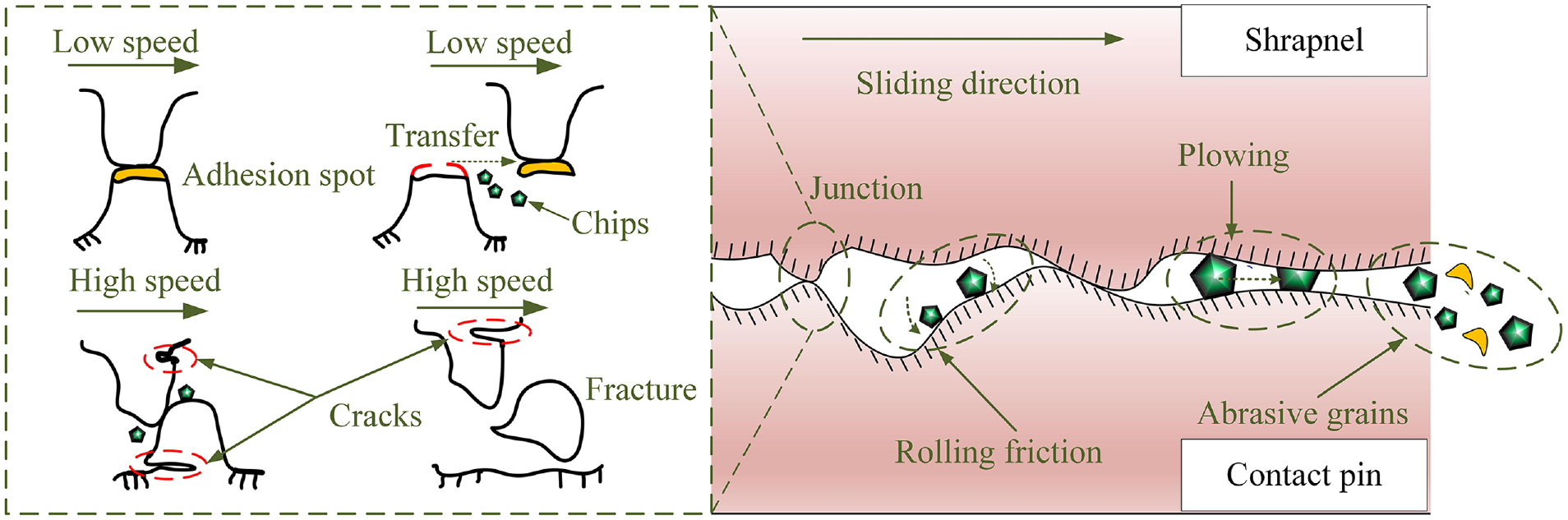
Schematic diagram of the form of wear.
Influence of ambient temperature and mating speed coupling on contact resistance
To investigate the influence of coupling factors and single factor on the relative variation of contact resistance during different mating cycles. A connector with an ambient temperature of 20°C and mating speed of 27 mm/s is defined as mating under high-speed conditions; a connector with an ambient temperature of 60°C and mating speed of 9 mm/s is defined as mating under high-temperature conditions; a connector with an ambient temperature of 60°C and mating speed of 27 mm/s is defined as mating under high temperature and high-speed. The relative variation of contact resistance of the connector at five test points is shown in Figure 7 under different working conditions. Then, the response surface graph of the contact resistance variation under the coupling of temperature and speed is made using the statistical software of Design-Expert® as shown in Figure 8.

Variation of contact resistance under single factor and coupling factors at each test point.

3D graph of contact resistance variation in coupling temperate and speed after 10,000 mating cycles.
As shown in Figure 7, the single factor and coupling factor have the greatest influence on contact resistance at the first 500 mating cycles and the influence on contact resistance becomes smaller with the increase of mating cycles. When the mating cycles are less than 1000, the influence of coupling factors on the variation of contact resistance is much larger than the influence of a single factor. After 1000 mating cycles, the influence of the single factor is greater than the coupling factors.
According to the results obtained, it is found that the material of the connector experiences an elastoplastic process in the process of mating, and different processes have different variations of contact resistance. Performing this comparison, the evolution of the contact performance of the connector can be divided into three distinct stages: the first stage where the entire contact area is elastic, the second stage where the contact area is elastic-plastic, and the third stage that the contact area is fully plastic. Kogut and Etsion 36 also concluded that the second stage of elastic-plastic contact lasted much longer than the first stage of elastic contact. At the first 500 mating cycles, the contact area is elastic and it is mainly for the wear of the silver plating layer, so the contact resistance increases quickly. At the 500–3000 mating cycles, the evolution of the contact performance of the connector has gradually changed from elastic to plastic. The shear strength of the material decreases and the thickness of the oxide film increases with the increase of temperature. Increased mating speed enhancing the probability of fracture of the micro-protrusion. Therefore, the influence of speed and temperature on contact resistance is intensified. The transition point from elastic deformation to plastic deformation is as the mating cycles are 3000. After 3000 mating cycles, the contact area is in a plastic process, the influence of temperature and speed becomes small. The effect of coupling factors accelerates the whole process, full plasticity has been reached before 3000 mating cycles.
As shown in Figure 8, the greatest value of contact resistance variation is 0.23 mΩ when the ambient temperature and the mating speed are respectively 60°C and 27 mm/s. The least value of contact resistance variation is 0.15 mΩ when the ambient temperature and the mating speed are respectively 20°C and 18 mm/s. The shape of the contour map can be used to determine the coupling effect between mating speed and ambient temperature. In the response surface model, the steeper the sloping trend, the more obvious the changing trend, which indicates that this factor has a greater impact on contact resistance. When the ambient temperature is fixed at any value, with the increase of the mating speed, the variation of contact resistance gradually decreases in the first but then increases. When the mating speed is fixed at any value, the contact resistance variation of the electrical connector increases rapidly with the increase of temperature.
According to the results obtained, it is found that the contact performance on the connector is more destructive under the coupling between the mating speed and ambient temperature. The influence of ambient temperature on the contact resistance is greater than the mating speed. This is because the increment of temperature reduces the shear strength of the material and increases the thickness of the oxide film, which deteriorates the physical properties of the material. Increased mating speed greatly increases the probability of fracture of the micro-protrusion due to collision, which results in the increment of wear and the reduction in contact pressure, leading to a rapid increase in contact resistance. Also with the increase of mating speed, a large amount of heat is generated during the entire mating process, which causes the increment of temperature.
Conclusions
The essential problem of the mating movement of the connector is friction and wear, which changed the mechanical and chemical properties of the connector. The variation of properties directly affected the contact performance of the connector. In this study, the evolution of contact performance was conducted by reliability accelerated testing. This study had examined the impact of the ambient temperature, mating speed, friction and wear on the material physics performance of connectors, which led to the evolution of contact performance contact resistance. Also the evolution curves of the contact performance of the electrical connector under different working environments were given and the reasons for the variation of contact resistance were analyzed from two aspects: oxidative corrosion of metals, friction and wear. The following conclusions were drawn from the present study:
The increment of temperature accelerated the diffusion of Cu+ and the rate of oxide film formation. Increased temperature reduced the shear strength of the material resulting in the decrement of contact pressure and contact points of the friction interface. As discussed above, that led to the increment of contact resistance. In preset parameters, when the ambient temperature was 60°C, the variation of contact resistance was the largest and the electrical performance of the connector was the worst.
The forms of wear on the friction interface were different at different mating speeds. Adhesive wear at low speed led to material transfer and produced a small amount of debris. This debris made compound friction at the contact interface. Peeling wear at high speed, a lot of debris was formed due to the collision of the rough peaks at the contact interface, and those were transferred out of the contact area with the mating movement, which resulted in a reduction in contact pressure. In preset parameters, the contact performance of an electrical connector was best at 18 mm/s.
The influence of ambient temperature and mating speed coupling on contact resistance was much greater than the influence of a single factor in the first 1000 mating cycles. Ambient temperature had a greater influence on contact resistance than mating speed. The coupling accelerated the entire process, and the connector had reached full shaping before 3000 times.
Footnotes
Handling Editor: James Baldwin
Author contributions
Conceptualization: Jing Ni, Jianfeng Pan, and Junqiang Zheng; validation: Lidong Han, Jing Ni, Yu Shi, Jianfeng Pan, and Junqiang Zheng; formal analysis: Lidong Han, Yu Shi, and Junqiang Zheng; investigation: Lidong Han; Zhi Cui, and Jun Cai, resources: Jing Ni; data curation: Jianfeng Pan, Junqiang Zheng, and Lidong Han; writing – original draft preparation: Lidong Han; writing – review and editing: Jing Ni, Jianfeng Pan, and Junqiang Zheng; project administration: Jing Ni; funding acquisition: Jing Ni.
Declaration of conflicting interests
The author(s) declared no potential conflicts of interest with respect to the research, authorship, and/or publication of this article.
Funding
The author(s) disclosed receipt of the following financial support for the research, authorship, and/or publication of this article: This research was funded by National key R&D program of China, grant number 2017YFB1301300.