
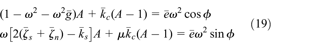
Abstract
This study investigates the stability and phase difference of a shaft mounted a dry friction damper with effects of viscous internal damping and gyroscopic moment. The equations of the system with the vibration reduction effect of the dry friction damper on the shaft are derived in the form of the rectangular coordinate and polar coordinate in the vicinity of critical speed. The phase difference characteristics in the rub-impact process and its physical mechanism are analyzed by mathematical derivation. The characteristic equation is studied to investigate the stability of the periodic solution. Effects of different parameters of the system, especially viscous internal damping of the composite shaft and gyroscopic moment on the phase difference and stability regions are presented in detail by analytical and numerical simulation based on a helicopter tailrotor driveline. The experimental investigation is conducted in a test rig to validate theoretical formulas and simulation analysis. The analysis results show that rub impact delays the change of phase difference, viscous internal damping improves the stability of synchronous full annual rub solution, and gyroscopic moment affects the increase of the phase difference.
Keywords
Introduction
The driveshaft in the supercritical regime has been commonly used in many helicopter tailrotor drivelines. The lateral amplitude of the transmission shaft increases significantly when crossing the first critical speed because of the inevitable eccentricity. 1 In an attempt to alleviate shaft vibration, dampers or shock absorbers are set in the drivelines. 2 Dry friction damper, as shown in Figure 1, is used in the certain helicopter tailrotor drivelines as an effective damper with the advantages of simplicity, reliability, and so on.3,4 The most important component of the damper is a damping ring, which is confined to the base by springs and has radial clearance between itself and the sleeve fixed on the shaft. The whirl of the shaft is restricted by the damping ring, which leads to the relationship between the shaft and the dry friction damper is similar to the rub-impact of the rotor-stator system.

Schematic diagnosis of shaft and dry friction damper.
There are two patterns of rub-impact motions, one is the synchronous full annular rub, that is, the sleeve slides and rotates along the inner surface of the ring at spin speed. The second is the partial rub, the sleeve contacts and separates with the inner surface of the ring intermittently. 5 Comparing with the first pattern, the partial rub is more likely to cause wear and tear due to repeated impact. 6 These two patterns can be distinguished through the stability evaluation of the periodic solution of the system. There is extensive research work on rub-impact phenomenon and stability,7–9 mainly including the stability of parameter regions and bifurcation boundaries analysis of rub-impact solution,10–12 bifurcation and chaos characteristics of the rotor-stator system,13,14 and analysis about the synchronous full annular rub and partial rub.15,16 Xu et al. 17 studied the full annular rub motion of a Jeffcott rotor and its dynamic stability by linear perturbation method and by the Routh-Hurwitz criterion, finding that the full annular rub motions exist in a wide spinning region of the rotor. Shang et al. 18 studied the global response characteristics of a general rotor-stator system. The dry friction effect is considered in the process of rubbing, which is regarded as the main factor for the self-excited dry friction backward whirl. Zhang et al. 19 studied the nonlinear dynamic characteristics of a rotor-bearing system with rub-impact, investigating effects of parameters such as eccentricity, stiffness of the shaft, and radial stiffness of stator on the system through the numerical calculation. Wang et al. 20 proposed a novel method of rubbing fault diagnosis based on variational mode decomposition (VMD) for vibration signal analysis of rotary machinery. Hu et al. 21 investigated the rub, crack and rub-crack coupled fault through experiments on a rotor test rig and analyzed the instantaneous frequency signatures of the faults. Wang et al. 22 developed a dual-rotor system with inter-shaft bearing able to describe the mechanical vibration caused by unbalance and fixed-point rub-impact, to understand the mechanism of fixed-point rub-impact in aero-engine.
Previous investigations are mainly based on the Jeffcott rotor, which is a typical lumped mass model But the internal damping effect due to the material of the shaft cannot be considered in this system. The application trend of composite transmission shaft in the helicopter tail rotor drive system is more extensive. This effect in the composite materials is more significant than metallic materials, so it cannot be ignored to ensure the accuracy of the analysis results.23,24 Even though the internal damping effect of shaft materials has been studied by some researchers, such as Montagnier et al. 25 investigated the stability region about the free movement of the rotating shaft. Desmidt 26 found that free whirl instability occurs at shaft speeds above the first critical speed and is related to the internal and external-damping ratio. Ren et al. 27 studied the dynamics of a rotating thin-walled composite shaft with internal damping analytically, showing the effect of design parameters on the instability thresholds of shafts. Monajemi and Mohammadimehr 28 examined the effects of viscous and hysteretic damping on the vibrational behavior and stability of a spinning Timoshenko micro-shaft. Ghasabi et al. 29 investigated the dynamic bifurcation of a viscoelastic micro rotating shaft, showing that the internal and external damping coefficients influence the critical speed, amplitude, and phase of a non-trivial solution, and radius of the limit cycle. Ben Arab et al. 30 introduced an Euler–Bernoulli shaft finite element formulation including the hysteretic internal damping of composite material and transverse shear effects, then used it to evaluate the influence of various parameters, including instability thresholds. Hosseini 31 modeled the shaft as an in-extensional spinning beam, which includes the effects of nonlinear curvature, inertia, and the internal damping, using center manifold theory and the method of normal form, analytical expressions are obtained, which describe the behavior of the rotating shaft in the neighborhood of the bifurcations. These researches are mainly about the instability of the free whirl or flutter of supercritical shafts, however, to the best of the authors’ knowledge, no research has involved the stability analysis for a rotating system with internal damping and undergoes unbalanced force and rub-impact.
The rub-impact phenomenon with non-linear behaviors is one of the classic research fields of rotor dynamics.32–34 Nevertheless, one can recognize that the phase difference between excitation and the response during rub-impact has not attracted enough attention in the current study. In fact, it can be regarded as another key point besides the amplitude for the dynamic characteristics of the system. The experimental results show that there is a great difference between the phase difference with and without rub impact. 35 There is a certain relationship between the change of phase difference, parameter conditions for the appearance of saddle-node bifurcation, and the transition from rubbing response to non-rubbing periodic response. 36 The specific phase difference characteristics in the rub-impact process and its mechanism need for in-depth and clear research, especially, the changes of phase difference after the application of composite transmission shaft.
In order to provide parameter guidelines for the design of dry friction damper used for slender flexible transmission shaft and reveal the mechanism of the phase difference, this paper focuses on the stability analysis and the change of phase difference about the shaft and dry friction damper system with viscous internal damping and gyroscopic moment under coupling of unbalanced force and non-linear rub-impact excitation. After this introduction, rub impact model between a slender shaft and a dry friction damper is established in Section 2. The relationship between the angular velocity of phase difference change and system parameters and criteria for stability and bifurcation are addressed by mathematical derivation in Section 3. Characteristics and mechanism of phase difference, effects of parameters, especially internal viscous damping and gyroscopic moment are studied by simulation in Section 4. The test rig is designed and experiments are conducted to verify simulation results in Section 5. Finally, conclusions are drawn in Section 6. A flowchart where the work flow of the present study is illustrated in Figure 2.

Flowchart of the present study.
Mathematical formulation and condition of contact occurrence
The dynamic model of the system
Figure 1 shows the schematic diagram of the shaft and dry friction damper. The shaft is rotating about the X-axis, relative to the inertia-fixed coordinate frame XYZ. The XrYrZr is a rotating frame coordinate with Xr coinciding with the rotation axis. Base on the governing equations of the slender shaft in Montagnier and Hochard, 25 Desmidt, 26 viscous internal damping (rotating damping) of shaft generated by the variation of the dissipative energy function, and external damping (nonrotating damping) provided by the bearing and block are distinguished and introduced in the governing equations. Then we obtain equations for a rotating shaft with disc:
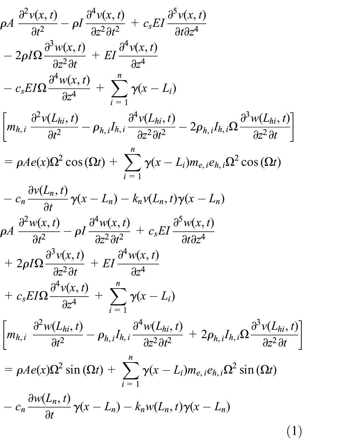
where the parameters in equation (1) are shown in the Notation Table. The Galerkin method is used to solve the above partial differential equations, the shaft transverse deflections and eccentricity are written in terms of the following modal expansion:

By substituting equation (2) into equation (1), multiplying the two sides of the equation by


Ref. has proved that taking the first two modes of flexible shaft system will guarantee the accuracy of the numerical simulation around the first critical speed to fourfold. While only the first critical speed is the interest region where damper works in this work, thus taking the first mode from can meet the requirement of accuracy in this work,

where


Rub impact between the shaft and damper.
where


The dimensionless equations are shown as

where non-dimensional variables are defined as

Solution existence region
We assume that the steady-state periodic solutions of equation (7) are the form as follow:

The unbalanced response increases significantly with the spin speed of the shaft after tailrotor drivelines start running. Noting that the rubbing force is zero until the shaft contacts the damper ring, and
Differentiating

If

When

In this paper,

where

Viscous internal damping does not enter the equation about synchronous full annual rub solution.
If
If
In this work, the eccentricity of the rotor system is strictly controlled, and the gyroscopic moment is very small because of the structure of the shaft itself, while the impact stiffness is relatively large by orders of magnitude, moreover, this study mainly concentrates on the first critical speed, so

Substituting

Because of the continuity of
In this section, the range of parameters in which dry friction dampers can work has been derived, the expression for rub-impact steady-state periodic solutions have been given, and the region of the existence of the solutions have been analyzed and discussed.
Phase difference and stability analysis
Mathematical derivation of phase difference
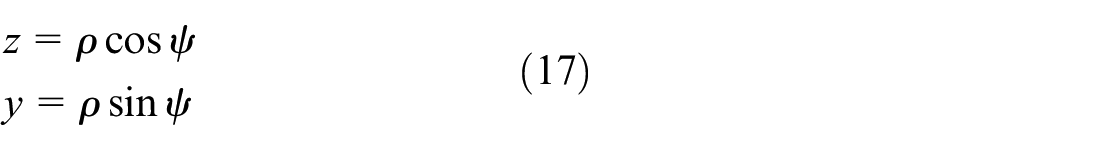
The phase difference of shaft, which is defined as the angle between the eccentric excitation and the response, is quite different with or without a dry friction damper. Once the rub between the sleeve and damper happens, the change of the phase difference is suppressed and maintained for a wide speed range. The equation governing motion in the Z–Y direction of the system cannot directly reflect the phase relationship and phase migration process, so the response of the axis trajectory is expressed in polar coordinates as follows
Substituting it into equation (7) and converting it into polar coordinates, the dimensionless governing equation in polar coordinate get

The non-dimensional variables are defined in equation (8).
By eliminating the amplitude A from the above formula, one gets

where

Substituting

Then, the corresponding expression for the tangent of the phase difference is obtained as

If

This expression is the same as
The critical position where the phase difference changes, that is,
If
If
Therefore, no matter under any conditions,


Through equations (24)–(26), the function curve of
If
If
If
To sum up, in the range of
Parameter criteria for stability and bifurcation
There are two patterns of rub-impact motions. The synchronous full annular rub will turn into partial rub after the occurrence of instability. Therefore, the stability of the solution is studied in this section. For the stability of the nonlinear dynamical system mentioned above, the equation can be approximated by the linear-approximation around its periodic solution, that is, the approximate linear system can be used to analyze the stability of the original system by its eigenvalues. Introducing state vector

Where

The steady-state periodic solution

where

where

According to the Floquet theory, the stability of the solution

Then, make the following transformation:

Equation (31) is substituted into equation (28), and yields

where


with

If
By substituting two periodic solutions

According to Zhang et al., 5 the boundary of Hopf bifurcation reveals the transition from synchronous full annular rub motion to partial rub motion. Therefore, the stability of the solution and Hopf bifurcation condition can be investigated by combining equation (35), equation (33), and equation (14).
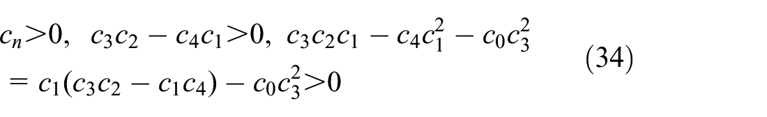
Saddle-node bifurcation occurs if one of the roots of the characteristic equation equals zero, that is

Combining equation (36) and equation (14), we get the parameter conditions for the change from the synchronous full annular rub solution to the saddle-node bifurcation, where the rub-impact motion disappears and the response converts to the non-rub periodic response. The rotational speed derived from this parameter condition corresponds to the
In this section, the characteristic equation and bifurcation including viscous damping and the gyroscopic moment are got. But what’s more concerned and interesting is the stability regions and boundaries with the change of bifurcation parameters. The variation and setting of these parameters are the key investigative factors to the design of the dry friction damper.
Simulation and discussion
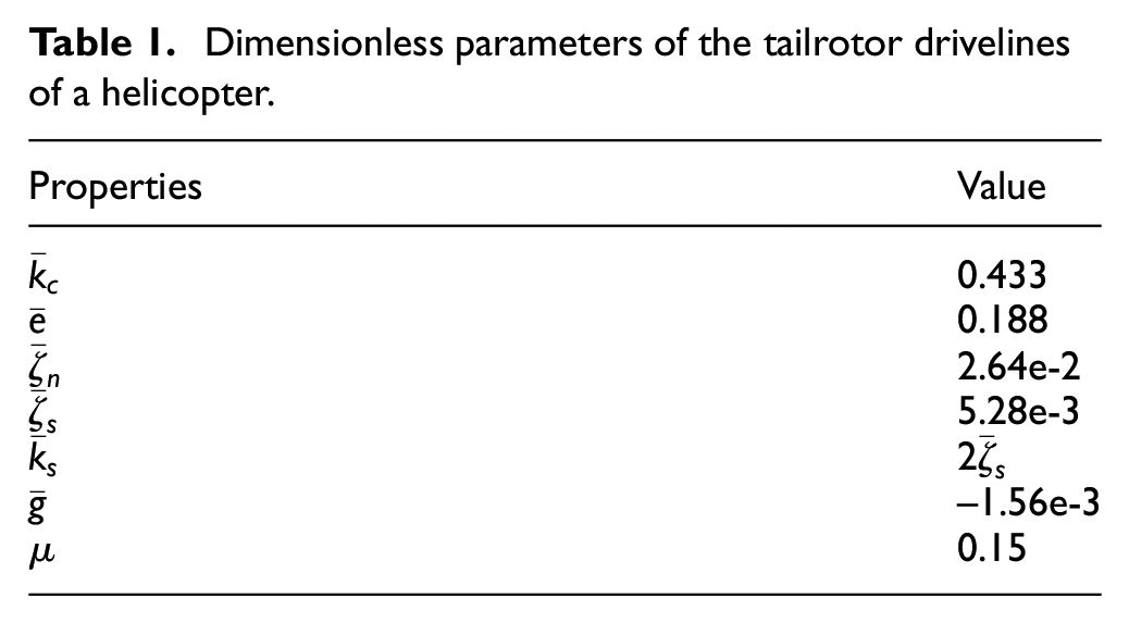
The simulation of this work is based on the practical parameters of the dry friction damper-shaft system on the tailrotor drivelines of a helicopter, as shown in Table 1 by dimensionless treatment. While gyroscopic moment and viscous internal damping are used as control parameters to investigate their effect on the phase characteristics and periodic solutions in detail employing the stability analysis method proposed above.
Dimensionless parameters of the tailrotor drivelines of a helicopter.
Characteristics and mechanism of phase difference
Figures 4 and 5 illustrate amplitude-frequency and corresponding the phase difference characteristics of the synchronous full annular rub solution derived from equation (14) and equation (20) based on parameters in Table 1. The dotted curves represent there is no damper, and solid curves represent the shaft equipped with the damper under excitation of the eccentricity and rub-impact. The amplitude and the phase difference of the shaft increase slowly when the rotational speed is far from the critical value. Once approaching the critical speed, both increases abruptly until the sleeve contacts the damper ring, where

Response characteristics for

Response characteristics for
To validate the theoretical formula, we plot the change of the value of

Value of
As mention in Section 2.2,
The physical mechanism of the above phenomenon can be explained as: if there is no damper, the phase difference of shaft will migrate from the same direction (less than
Effects of iViscous internal damping
The viscous internal damping of the composite material shaft is larger than the metal shaft, 13 so it is considered as the primary parameter when a dry friction damper is designed for the composite shaft.
Above all, the regions and boundaries in the following figures should be introduced. The amplitude of the shaft isn’t significant enough to contact the damper ring with low speed. The rub-impact occurs as the speed approaches the first critical speed. Therefore region I is the non-rub region, II is the partial rub region and III is the steady-state periodic solution region, that is, the synchronous full annual rub region. HP is the Hopf boundary between region II and III. ω1, ω3 are boundary between the non-rub region and the rub region. ω1, ω2, ω3 correspond to the angular velocity in the previous theoretical analysis.
Figure 7 illustrates the effect of internal viscous damping and skew-symmetric stiffness on response characteristics and stability domains. Viscous internal damping of metal materials is trivial compared with composite materials, even ignored in Ozaydin and Cigeroglu.
4
Therefore,

Response characteristics of viscous internal damping
Figure 7(a) shows that the stability boundary value of friction coefficient decreases at first, and then increases with the increase of frequency ratio
Conversely, the stability boundary value of external damping firstly increases first, and then decreases with the increase of frequency ratio
In the upper part, the effect of viscous internal damping on periodic solutions has been analyzed, further study focuses on the influence of it on quasi-period solutions. It is difficult to deduce the expression of the solution with
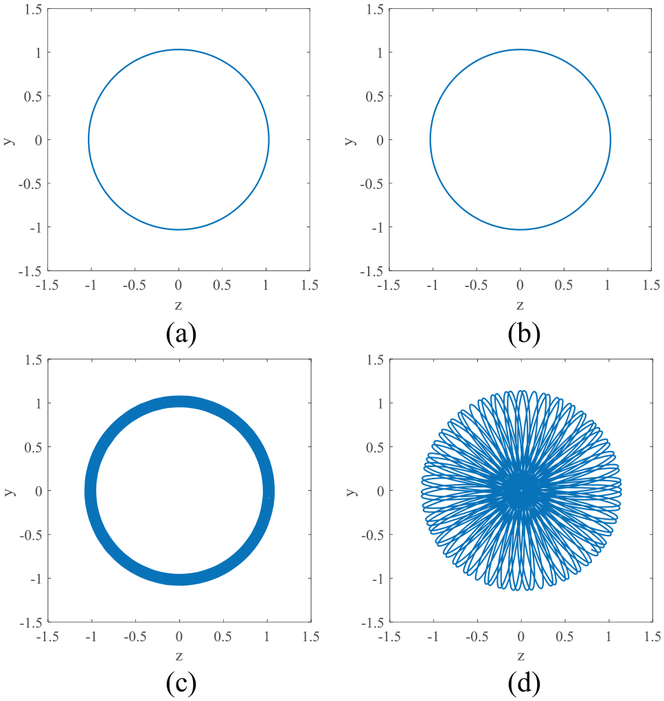
Axis orbit of shaft in Case 1 and Case 2: (a) P1,
Viscous internal damping shows destabilizing effects on free whirl or flutter of shafts in the supercritical range according to Montagnier and Hochard. 25 But the above study can be summarized that under unbalanced force and rub-impact excitation, internal damping improves the stability of periodic solutions in subcritical and supercritical range.
Effects of gyroscopic moment
Due to the structural characteristics of the slender shaft, the influence of the gyroscopic moment seems trivial in this work, but in the multi-disk rotor system, the influence of the gyroscopic torque can not be ignored. Therefore, the effects of the gyroscopic moment are amplified to observe the stability and the phase difference.
Figure 9 is used to demonstrate the effect of the gyroscopic moment on the stability of periodic solution and boundaries. Subscript 0, −, + correspond to

Response characteristics of the gyroscopic moment
The response characteristics of the gyroscopic moment on phase difference is illustrated in Figure 10. The gyroscopic moment affects both the synchronous full annual rub solution and the non-rub solution as previously studied. For the case of non-rub, the increase of the phase difference delays after reducing the gyroscopic moment. The curves move to high-speed region, and the first-order critical speed increases, as displayed by

Response characteristics of the gyroscopic moment
Experimental investigation
Test rig design and experimental setup
Considering the structure of the tail drive system of the dry friction damper-shaft system on the tailrotor drivelines of a helicopter, the simulated experiment test rig has been designed by the similarity principle, as shown in Figure 11. The parameters of its components are shown in the Table 2. The dimensionless parameters of the test rig are designed to be as close to the original system as possible, so as to preserve the characteristics of the original system. Horizontal and vertical eddy current transducers are set in two locations. One is the driveshaft near the damper mounting to measure the whirl of the drive shaft, another is the motor output shaft to measure the excitation of the spin of it. In this way, the phase difference is obtained from the difference between them. Discs are designed to be small so as not to interfere with the mode of the shaft. The damper adopts similar materials and structural features as the actual dry friction damper. In order to validate the analytical formula and simulation results and ensure the repeatability of the experiment, experimental studies are conducted on the test rig adopting loading protocol as follows:.

Diagram and configuration of a simulated experiment test rig for the helicopter tailrotor driveline.
Parameters of components.

Three cases are set:
The metal drive shaft is mounted with the disc in the initial position.
The metal drive shaft is mounted and two discs are moved 200 mm toward the center, respectively.
The composite drive shaft is mounted with the disc in the initial position.
Each case is divided into the following two groups:
The response data from star-up through the first critical speed of the shaft with the damper.
The response data from star-up through the first critical speed of the shaft without the damper.
Each group needs to collect amplitude and phase difference data separately: The amplitude is based on sampled data at uniform time interval. The phase difference is based on speed tracking and angle domain resampling to record the whirl of the drive shaft at a fixed phase point for each revolution of the motor output shaft.
Simulation validation
Firstly, the amplitude-frequency characteristics from star-up through the first critical speed are depicted in Figure 12 based on data derived from the test and simulation, respectively. The simulation is still adopted the above method based on the dimensionless parameters in Table 3. Experimental curves are plotted with all the collected data of vibration displacement in Y-axis. The amplitude variations in the experiment are similar to the simulation results, but the experimental response under the rub impact of the damper is slightly delayed comparing with the simulation. According to the parameters of the test rig,

Experimental response characteristics for
Dimensionless parameters of the test rig.

The phase-frequency characteristics is depicted in Figure 13. Smooth curves represent simulation results, the experimental results with fluctuations match with them to some extent. Key speed points

Experimental response characteristics for
Effect of the gyroscopic moment and viscous internal damping validation
Moving the axial position of discs can change the gyroscopic moment of the system, which is used to examine the effect of the gyroscopic moment on response characteristics. The change of it is in a limited range since the disc mass is small. Two discs are moved 200 mm toward the center of the shaft, respectively. Then

Experimental response characteristics of gyroscopic moment
Viscous internal damping comes from the material of the shaft in the rotating frame. In the above Section 4.2 has simulated and illustrated that viscous damping changes the partial rubbing response and leads to less chaos. To validate the effect of it, a flexible matrix composite shaft (bending elastic modulus 117 Gpa and Poisson’s ratio 0.307) with the same structural dimensions is installed on the test rig instead of a metal shaft, as shown in Figure 15. Viscous internal damping of carbon fiber reinforced laminate composite varies with fiber orientation and the number of layers, but the value of it is much larger than metal anyway.
25
So

Flexible matrix composite shaft.
The axis orbit of metal and composite shafts under the restriction of dry friction damper at dimensionless critical speed is shown in Figure 16. When the composite driveshaft is installed in the test rig, there are slight partial rub between the sleeve on the shaft and the damping ring, showing a circular ring. However, when the metal shaft is installed, serious rubbing occurs, showing an irregular petal shape. The results show clearly that the vibration response changes from chaotic motion to quasi-periodic motion only by the increase of the damping. If the processing, installation error, data noise, and other factors are ignored, these characteristics correspond to Figure 8(c) and (d). The results also demonstrate that the internal damping affects the partial rub. The increasing of the internal damping can alleviate the chaotic effect of the response of the shaft under rub impact.

Axis orbit of shaft of: (a) composite shaft and (b) metal shaft.
Conclusion
The stability and the phase difference of a shaft mounted a dry friction damper system with effects of viscous internal damping and gyroscopic moment are investigated in this paper. The phase difference characteristics and its mechanism are analyzed in the view of formula derivation. The stability and bifurcation of rub-impact solutions with considering viscous internal damping of the shaft, especially the composite shaft and gyroscopic moment are derived. According to the helicopter tailrotor drivelines, boundaries of synchronous full annual rub motion and partial rub and phase difference are analyzed and discussed by analytic and numerical simulation method.
Rub-impact will be maintained for a long time after the speed is greater than the critical speed because of the limit from the damping ring. The stability of rub-impact solution can be improved by choosing materials of damping ring with low friction coefficient, or increasing external damping in bearing and block. Viscous internal damping affects partial rub motion and improves the stability of synchronous full annual rub motion in the subcritical and supercritical range. While gyroscopic moment has little effect on the stability of the solution, but it affects the rub-impact boundary and the increase of the phase difference. The experimental investigation is conducted in a test rig whose characteristics are similar to the tailrotor driveline of a helicopter. Experimental results have verified the simulation results and theoretical derivation. The trend of the amplitude and the phase difference is consistent with the simulation. The increase of the gyroscopic moment causes movement of the change of phase difference to the high-speed region. The increasing of the internal damping can alleviate the chaotic effect of the response of the shaft under rub impact and proves the stability of synchronous full annual rub solution.
Footnotes
Appendix
Handling Editor: James Baldwin
Declaration of conflicting interests
The author(s) declared no potential conflicts of interest with respect to the research, authorship, and/or publication of this article.
Funding
The author(s) disclosed receipt of the following financial support for the research, authorship, and/or publication of this article: Funding “Damping Parameter Design and Wear Analysis of a Dry Friction Damper” (KY-44-2019-0089) from China Aviation Powerplant Research Institute is gratefully acknowledged. The authors also wish to acknowledge Dr. Chuliang Liu for his help in the revision of this paper.
Data availability statement
All data generated or analyzed during this study are included in this article.