
Abstract
Most of the time, mass eccentricity, and misalignment exist at the same time with aviation spline coupling working. Therefore, in this paper, the function of dynamic meshing force between multi-teeth and a non-linear dynamic model of involute spline coupling system in aero-engine with mass eccentricity and misalignment were presented. And then, the non-linear dynamic meshing force of spline coupling in aero-engine on different misalignment and mass eccentricity was investigated. The result shows that when the mass eccentricity and the misalignment are both small, the aviation involute spline coupling can run steady. And with the increase of mass eccentricity or misalignment, the dynamic load coefficient of the aviation involute spline coupling gradually increase. At the same time, as the mass eccentricity or misalignment increases, some teeth suffer more load, some teeth suffer less load, and some teeth are out of engagement so that they do not suffer any load. The running state of spline coupling becomes more and more unstable.
Introduction
Involute spline coupling of aero-engine are suffering periodic fluctuation loads while taking-off, cruising, and landing. Such loads will induce alternating contact stress on the working surface of spline couplings, and cause a vibration with small amplitude between contact surfaces. Due to this vibration caused by the internal and external excitations cannot be eliminated and avoided, it leads to fretting wear of spline couplings. The damage of fretting wear is invisible, which can seriously weaken the stability, safety, and reliability of the spline coupling in aero-engine. Therefore, the estimation of fretting wear of involute spline coupling in aero-engine remains a hot topic in the field of engineering.1–3 And from the calculation formula of fretting wear, it can be seen that the wear coefficient, relative slide distance, and contact stress are all the basic parameters for the calculation of fretting wear.4–6 The relative slide distance is a combination of the slide distance between the friction surfaces of two spline couplings and their vibration displacement under fluctuating loads.5,6 However, the relative slide distance and the contact stress of involute spline coupling must be calculated based on the dynamic force between spline teeth. Thus, the dynamic load is the key to the design and optimization of spline coupling, as well as an important basis for accurately estimating the fretting wear of spline coupling.
In recent years, the studies on the dynamic meshing force of the spline coupling are mainly in two aspects: the vibration characteristics of spline couplings and the contact mechanics model of splines. For the study of the vibration characteristics of involute spline couplings, a piecewise linear dynamic model of a spline joint subjected to both backlash and circumferential tooth position errors was proposed by Kahraman. The equation of motion with a piecewise linear displacement function was obtained in the dimensionless form. For cases with a large number of spline teeth, a generalized approximation that reduces the piecewise linear displacement function into a piecewise non-linear one was proposed, and its accuracy was demonstrated using a case of linearly varying tooth position errors. 7 Nataraj and Kappaganthu 8 studied the nonlinear dynamics of two rigid rotors that are connected by splines, and the coupling had the Coulomb friction. The study indicated that the system had three unstable fixed points and a limit cycle when the system ran at a speed above the critical value, and the response near the limit cycle showed signs of chaos. Park 9 performed all-round numerical calculations and experimental studies on loose-fit spline coupling and the rotor-bearing system. The results showed that the stability of the rotor system could be improved by lubricating the spline. At the same time, misalignment also affects the dynamic behavior of the rotor system.10,11 Zhao et al. 12 established a dynamic model of spline considering the misalignment, and calculated and tested the dynamic characteristics of the spline-rotor system. The study showed that misalignment could cause complex double-frequency vibration in the shaft system, and loose-fit sleeves/spline coupling are subject to self-oscillation.13,14 Tuckmantel and Cavalca proposed the comparison between two approaches for modeling the forces and moments generated by a metallic disc coupling under angular misalignment. The first is a well-established model based on the linear bending flexure of the disc packs, assuming the misalignment efforts are the sum of the first four harmonic components. In the second approach, a structural analysis of the coupling was conducted through finite element method, where the cyclic nature of coupling efforts was captured by the application of consecutive shaft spin angles. 15 For the spline contact mechanics model, Sum et al. 16 pointed out that the local mesh can be refined by MPCs. This is an effective way to realize the finite element analysis of splines under asymmetric loads. Liu et al. 17 calculated the contact characteristics of the connection of spline couplings in aero-engine by the finite elements and verified it with tests. Peng and Li 18 established a bending and squeezing deformation model for the spline with single-tooth meshing, and derived the formulas for bending, shearing, and squeezing of single-tooth meshing. Silvers et al. 19 proposed a sequential expansion model and a statistical analysis model for predicting spline meshing. Barrot et al.20,21 derived the torque between spline teeth, and they also studied the stress and axial load distribution of the spline coupling by the finite element method and established equations for the torsional stiffness as well as the sectional moment of inertia. Medina and Olver 22 built meshes by the finite elements to perform boundary element integration. The stress of each node on spline was obtained. Tjernberg 23 obtained an accurate equation of stress concentration factor, and conducted the fatigue testing combined with finite element analysis. The results showed that spline shafts can withstand higher stresses if they are heated and quenched, and the average axial load distribution can reduce the stress concentration at the root of teeth. Zhu and Yao 24 derived the circumferential force and connection stiffness of the involute splines without clearance. Although the above researchers have done a lot of research on the vibration characteristics and contact mechanics models of spline couplings, and even some studies have also considered the impact of misalignment,25–27 but nearly none of them emphasized on the dynamic meshing force of spline couplings in aero-engine. In fact, during the operation of the involute spline coupling of aero-engine, there are gaps, misalignment and eccentricity between teeth due to the manufacturing errors. Even though, at the beginning, the spline coupling was dynamically balanced before installation, and there was no mass eccentricity. However, in the operation process, due to the uneven backlash on the tooth side, only part of the teeth participated in the meshing. As the number of load cycles increased, the wear amount at different positions of the spline tooth surface was different, so the mass eccentricity gradually occurred, and the mass eccentricity became larger and larger. These three issues may exist in the operation individually or simultaneously, which seriously affected the system’s stability during operation. The dynamic parameters of the involute spline coupling of aero-engine and its dynamic meshing force will be significantly affected by these three factors. However, the above literature did not consider the coupling effect of these factors to analyze the dynamic meshing force of the involute spline coupling of aero-engine. In addition, in these researches, the calculation of the meshing force is based on the meshing with single tooth and meshing line with a fixed position. For the multi-tooth meshing of involute splines, each single tooth has a meshing line at the corresponding position. The position of meshing line is a function of the rotational position and the number of the teeth pair due to the existence of rotation. For the single-tooth meshing of involute splines, the position of the meshing line is time-varying. The teeth with different numbers of pairs have meshing lines in different directions, and it is resulting in different components of teeth meshing forces on the coordinate axis. Besides, there are different clearances and meshing deformations, as well as different meshing forces because of vibration.
In this work, in order to get the more accurate dynamic load, the model and equation of meshing force between the involute spline coupling was obtained considering the coupling effect of mass eccentricity, misalignment, and clearance, and then, the non-linear meshing force of spline coupling on different misalignment, mass eccentricity, and clearance was studied. The most important is that the model, equation and results of meshing force were all based on the multi-tooth meshing theory. It provides a good foundation to the predict on the fretting wear and fretting fatigue of spline coupling, and it is very important to design the involute spline couplings in aero-engine of high reliability, high accuracy, and high performance, as well as provides a good idea and method for dynamic load analysis of other parts with mass eccentricity and misalignment.
Calculation of dynamic meshing force of the system
Calculation of the displacement on meshing line
In Figure 1, a ray OK was drawn through the intersection point A of reference circle and external spline tooth profile, taking the center of circle O of the external spline shaft as the starting point. And then a segment AN tangent to base circle of external spline at point N was drawn, taking point A as the starting point.
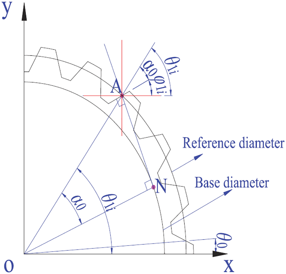
Schematic diagram of the rotational angle of a single tooth on the external spline.
So, it can be obtained from the property of the involute that
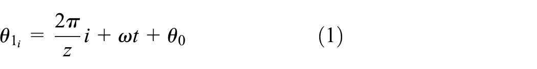
where,

As shown in Figure 2, the intersection point of the working teeth profile and the reference circle is point A at the initial moment. Due to the transverse vibration displacement, the working teeth profile of the external spline moved from the black oblique line to the red oblique line. Accordingly, point A moved to


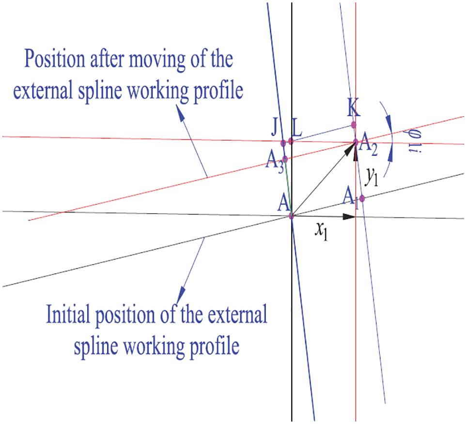
The displacement of single tooth of external spline along the meshing line (
If the external spline in Figure 2 is considered moved by a distance of

and then:


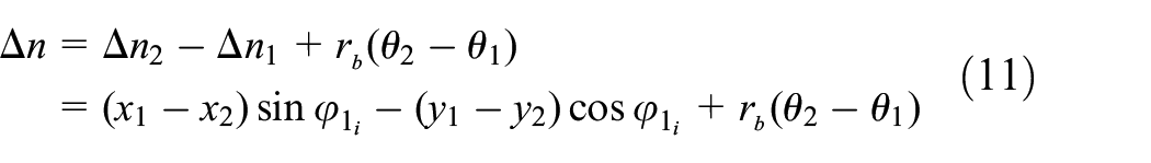
Therefore, the relative displacement distance on the meshing line on the external and the internal splines are shown as follows, respectively:


Due to the analysis processes for the external and the internal spline moving along the x-axis and the y-axis in other quadrants are similar as above, that is to say
Dynamic parameters
As for spline coupling, it is characterized as a multi-tooth meshing, and the number of tooth pair in-mesh is varying with the vibration, as well as the mesh deformation of each pair of teeth is also different. Therefore, the comprehensive meshing stiffness suitable for gear dynamics and pure torsion models of involute splines is no longer applicable. Here, in order to calculate the meshing force, the single-tooth meshing stiffness is calculated firstly, and then the single-tooth meshing force is obtained based on the single-tooth meshing stiffness. Finally, the total meshing force of the involute spline coupling is obtained by summing the single-tooth meshing force.
And the single-tooth meshing stiffness can be expressed as in Xue et al.: 15

where,

where,

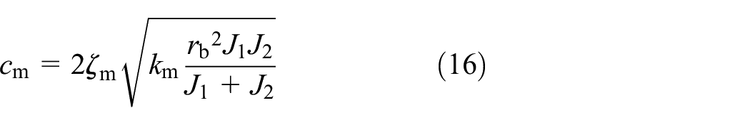

In formula (16) and (17),
Nonlinear dynamic meshing force
Due to the clearance, the meshing force of a single tooth is a piece-wise linear function. Whether positive or negative of its value is mainly related to the clearance. If the relative displacement on the meshing line in the positive direction is greater than the clearance of the working teeth profile, the working teeth profile is regarded as being meshed and the meshing force is negative; if the relative displacement on the meshing line in the negative direction is greater than the clearance of the non-working teeth profile, the non-working teeth profile is regarded as being meshed, and the meshing force is positive; and if the relative displacements on the meshing line both in the positive and negative direction are less than the clearance of the working teeth profile and the non-working teeth profile, it is considered that there is no meshing force. Therefore, the meshing force of single tooth is (the value of the meshing force on the external spline and the internal spline is the same, but the direction is opposite):
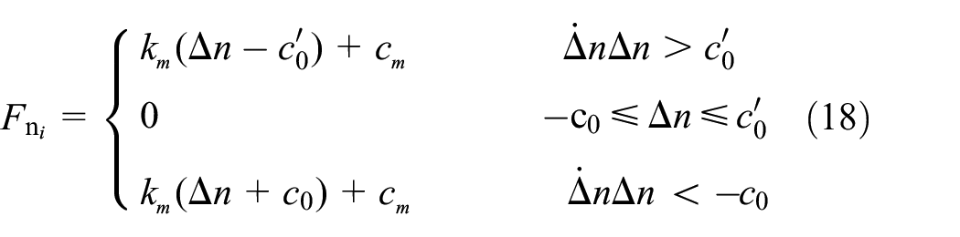
where,
The formula of the total meshing force and meshing torque are the summation of the meshing force components and meshing torque components along x and y direction, respectively:
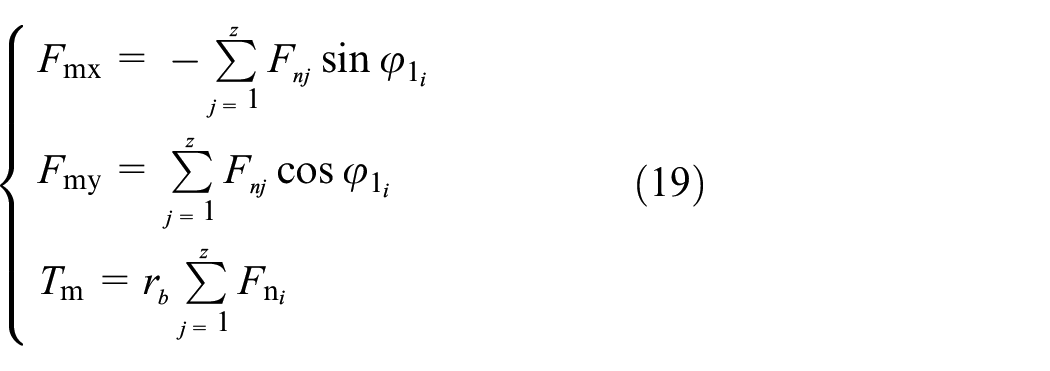
where,

A flow chart for the calculation of the dynamic meshing force of the system.
Dynamic models and equations
Dynamic models
In this work, the lumped mass method was used to simplify the system, and the dynamic model of the aviation involute spline coupling system was established by comprehensively considering the effect of mass eccentricity, misalignment, and clearance (as shown in Figures 4 and 5). In Figure 4, four ellipses were used to represent the components, which are prime mover, external spline, internal spline, and load respectively. In Figure 4, x1 axis of the coordinate system where the center of the external spline was located coincides with the x2 axis of the coordinate system where the center of the internal spline was located. The center (x2, y2) of the internal and spline moved along the x-axis for a distance

The dynamic model of involute spline coupling in aero-engine.
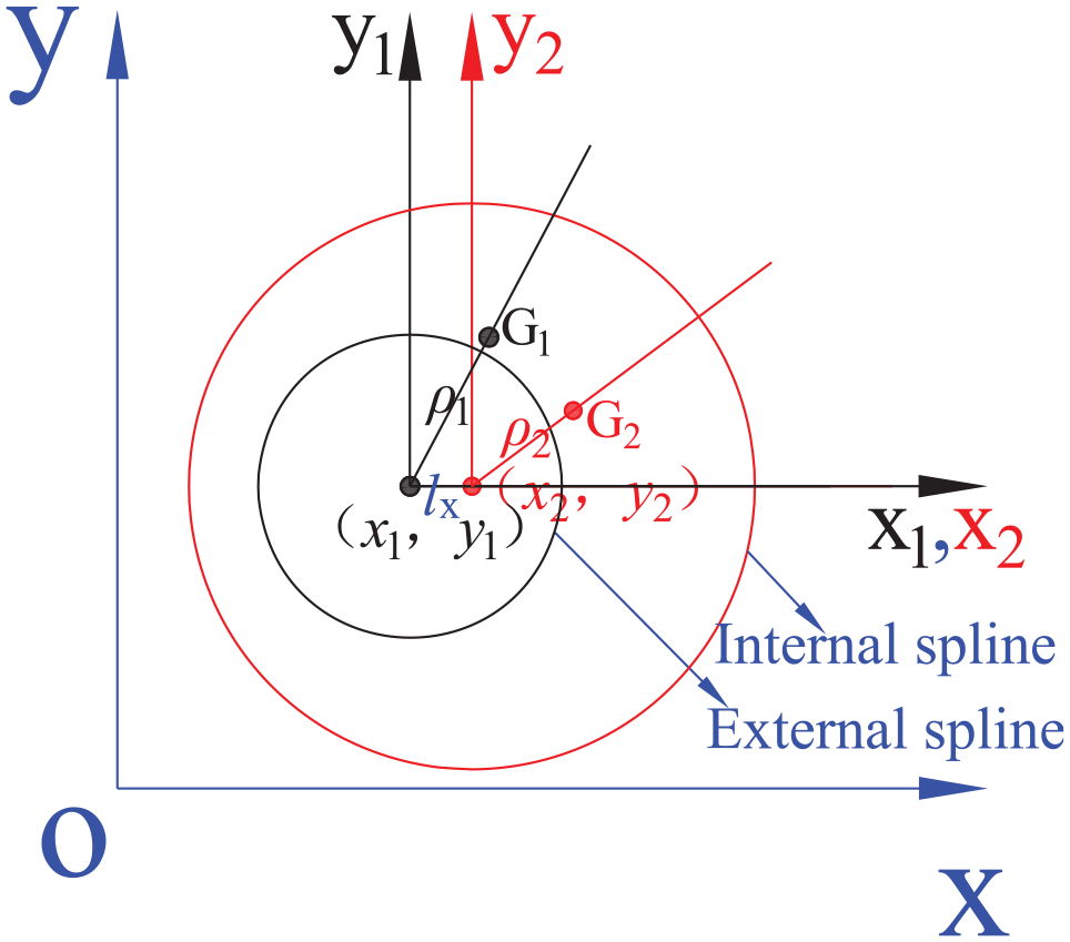
Mass eccentricity and misalignment diagram.

While

and

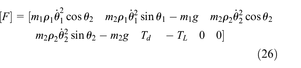
in which:

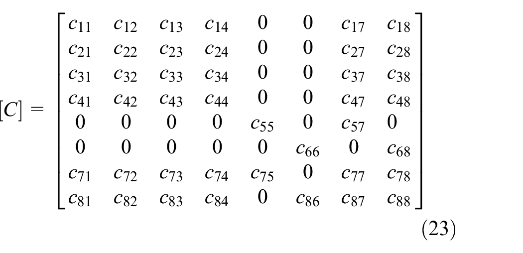


in which, the nonzero elements in matrix


The angular velocity
The dimensionless reference parameter

in which:


where the nonzero elements in matrix
Analysis of dynamic load of spline coupling under multi-factors action
The geometric parameters of an aviation involute spline are as follows: the modulus m is 2.5 mm; the number of teeth is 22; the pressure angle is 30°; the meshing stiffness of single spline tooth is km = 1.5972 N/m;
The results of nonlinear dynamic meshing forces of the system under the action of multiple factors were discussed in section 4.
Dynamic load of spline coupling under different mass eccentric
When
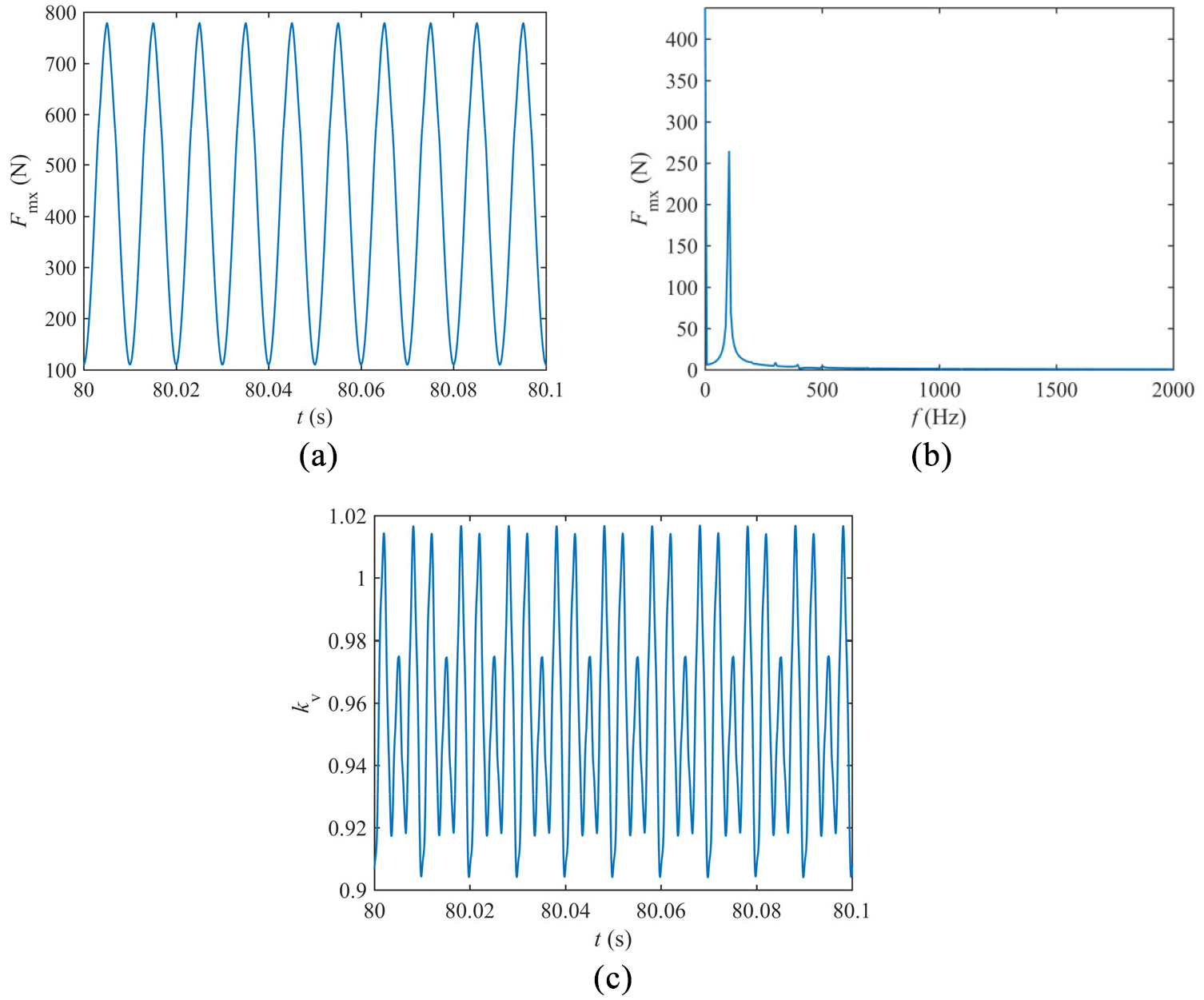
Dynamic load of involute spline coupling when

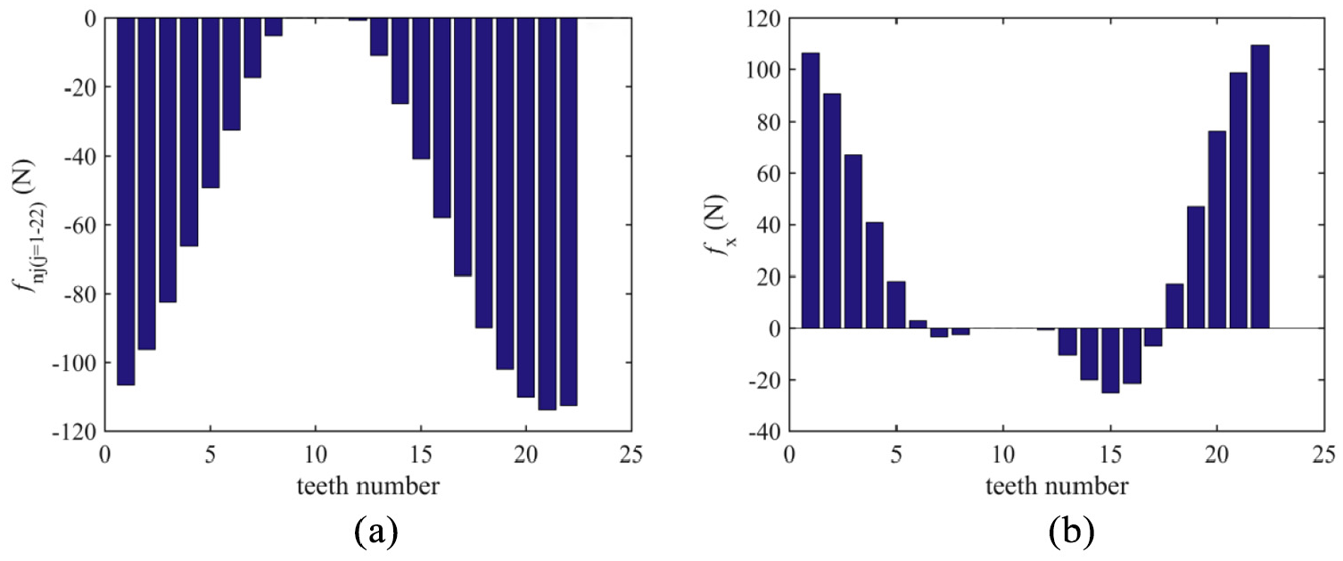
Dynamic load of each tooth when
Dynamic load of involute spline coupling when
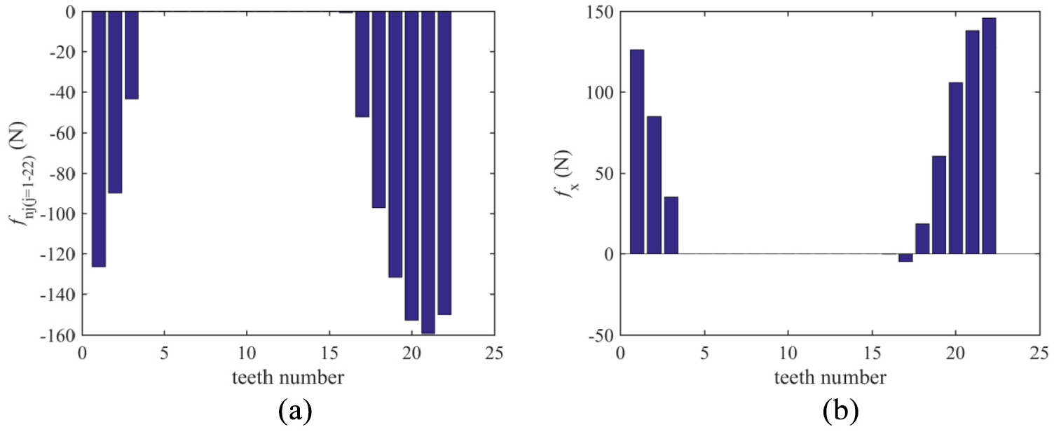
Dynamic load of each tooth when

Dynamic load of involute spline coupling when

Dynamic load of each tooth when

Dynamic load of involute spline coupling when
Dynamic load of each tooth when
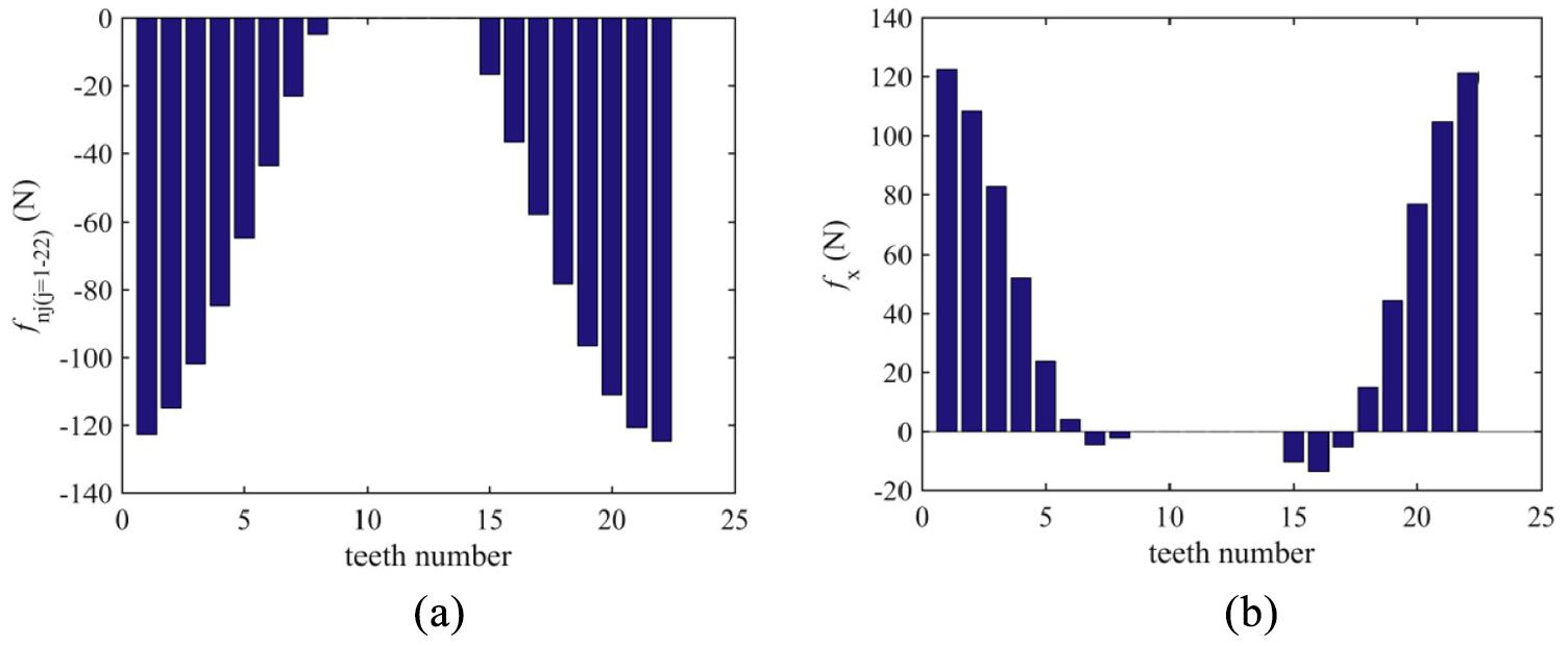
Figure 10 shows the dynamic load situation of the spline coupling when the mass eccentricity is
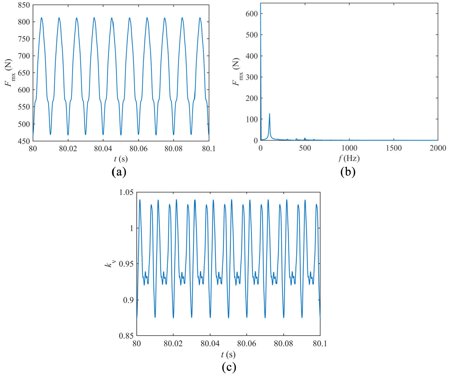
When the mass eccentricity increases to
Misalignment
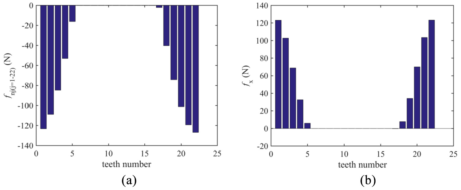
When the mass eccentricity is
Dynamic load of involute spline coupling when
Dynamic load of each tooth when

Dynamic load of involute spline coupling when

Dynamic load of each tooth when
Dynamic load of involute spline coupling when
Dynamic load of each tooth when
Conclusion
Therefore, it can be concluded by investigating the non-linear dynamic load of involute spline coupling in aero-engine with mass eccentricity and misalignment that:
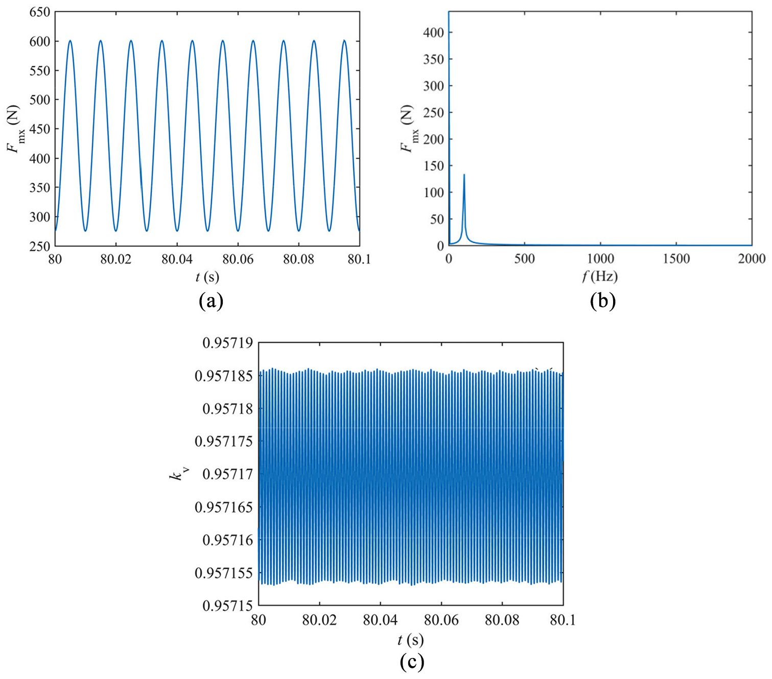
when the mass eccentricity and misalignment were all small, the total meshing force in the x-axial direction and dynamic load coefficient of the aviation involute spline coupling are relatively stable. That is to say, the aviation involute spline coupling can run steady under this situation.
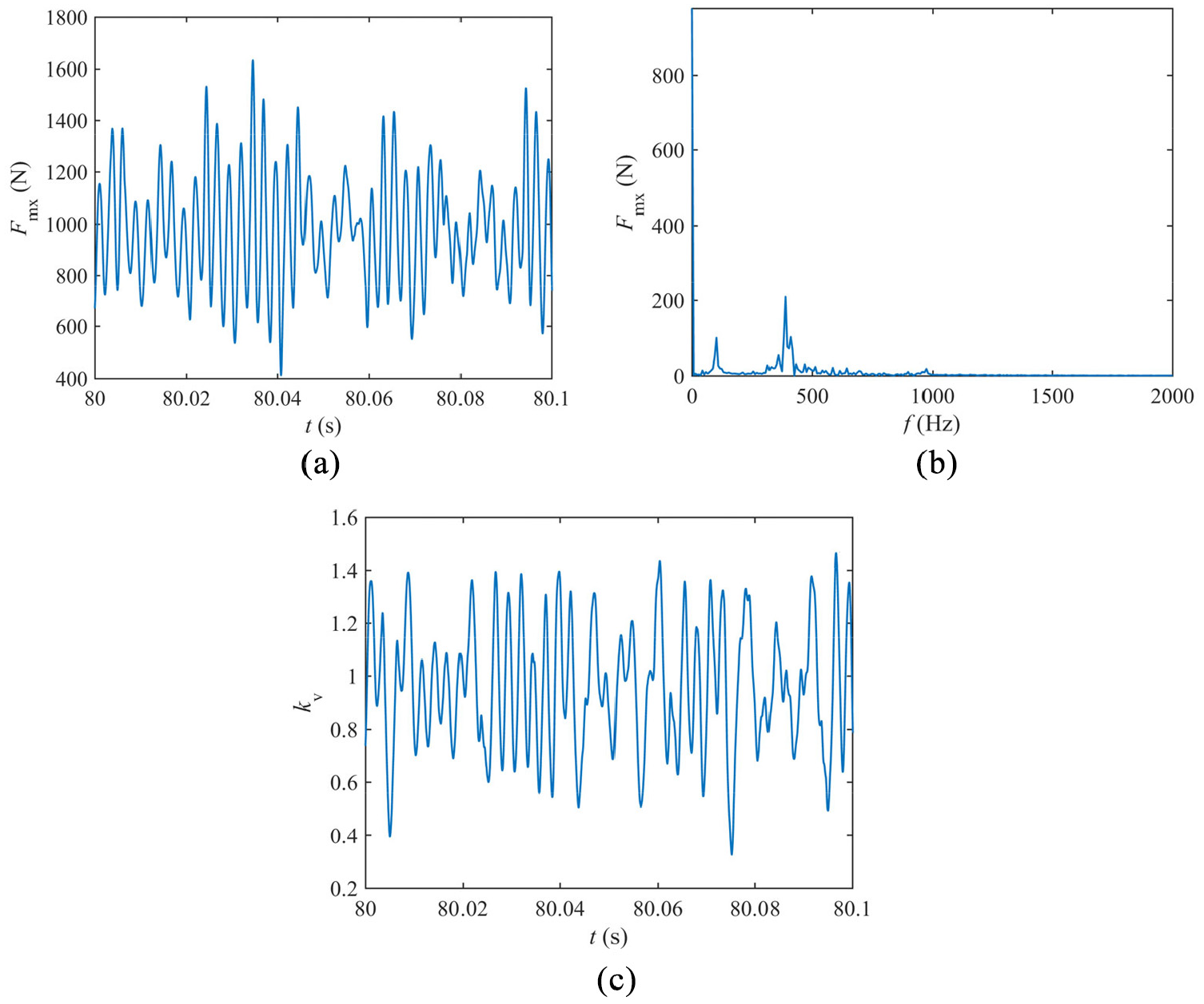
the frequency component corresponding to the meshing force peek value approximately meets the double frequency relationship, and the lowest frequency approximately equals to the double rotation frequency, but it is not a very accurate mathematical relationship. It because that the spline belongs to the multitooth meshing, and the separation and engagement of teeth do not obey the strict law while the spline running, which has a certain impact on the frequency of the meshing force. However, with the increase of mass eccentricity or misalignment, all of the maximum value of the total meshing force along x direction, and the fluctuation range of the dynamic load coefficient of the aviation involute spline coupling gradually increase.
from Figures 7 to 13, it can be concluded that the load sharing between each tooth are very uneven with the increase of eccentricity of the spline coupling. It can be seen that some teeth were suffering more load, but some teeth suffering less load, and even some teeth were not suffering any load at all. And with the increase of eccentricity, misalignment, or clearance, the teeth number of out of engagement on the spline coupling were more and more, which poses a serious threat to the strength of spline coupling. As well as it made the spline coupling becomes more and more unstable. When the eccentricity, misalignment, or clearance is large enough, some teeth were suffering too much load, the spline coupling leads to spline failure. Therefore, the auxiliary centering structure should be designed while designing the spline coupling, so that the spline coupling can operate under the condition of absolute alignment or only small misalignment; at the same time, in the processing and manufacturing, the machining error and assembly error should be strictly controlled, so that the mass eccentricity and tooth clearance can be well controlled, and finally the load distribution of the spline coupling will be uniform, and the number of teeth involved in the meshing will be as many as possible.
and also, the function of non-linear dynamic load and non-linear dynamic model of involute spline coupling in aero-engine presented here provides a good method to the analysis on multi-teeth meshing structures with mass eccentricity and misalignment, and gives a good and important reference to the designing the involute spline with high accuracy, high reliability, and high strength.
Footnotes
Appendix I
Parameters and the corresponding formulas before and after the eliminating the rigid body displacement and non-dimensionalize.
Where:
Handling Editor: James Baldwin
Declaration of conflicting interests
The author(s) declared no potential conflicts of interest with respect to the research, authorship, and/or publication of this article.
Funding
The author(s) disclosed receipt of the following financial support for the research, authorship, and/or publication of this article: The authors gratefully acknowledge financial support from the National Natural Science Foundation (Grant No. 52005312), the National Natural Science Foundation of Shaanxi in China (Grant No. 2019JQ-457), and Special Scientific Research Plan Project of Shaanxi Provincial Department of Education in China (Grant No. 19JK0147).