
Abstract
The hydraulic and acoustic performance of centrifugal pump is closely related to hydraulic structure parameters, and they are contradictory. In order to solve this contradiction, this paper introduces the pit bionic structure, and proposes an optimization method based on multi-objective test design and response surface to improve the hydraulic and acoustic performance. Taking the bionic vane pit diameter, axial spacing and radial spacing as design variables. Taking the maximum hydraulic efficiency and total sound pressure level reduction of centrifugal pump as the corresponding objectives. The multiple regression response surface model was constructed to determine the optimal parameter combination of hydraulic performance and noise collaborative optimization. The optimization results were verified by numerical simulation and experimental test. The results show that the response surface multi-objective optimization method has high prediction accuracy, has obvious synergistic effect on the hydraulic and acoustic performance. The highest point of the efficiency curve after optimization is shifted to the direction of large flow, which widens the high efficiency working area of centrifugal pump. Under the rated condition, the hydraulic efficiency is increased by 3.03%, the efficiency increase rate is 4.21%, the total sound pressure level is reduced by 4.96 dB, and the noise reduction rate is 3.01%.
Keywords
Introduction
Energy shortage and environmental pollution have become hot issues of global concern. Improving energy utilization and reducing energy consumption is one of the effective ways to solve the problem. 1 Pump is one of the most suitable equipment for pumped storage power station and small hydropower station due to its low cost, high efficiency and high flexibility. 2 The improvement of the centrifugal pump efficiency as well as the operation stability is of great significance. However, the hydraulic performance and acoustic performance of traditional centrifugal pump are considered separately. There is a lack of design theory and method to take both into account.
In recent years, scientists have found that the surface structure of shark, owl, beetle, dung beetle, and other natural creatures is not smooth. After a long time of natural evolution and biological selection, its surface microstructure adapts to the living environment and has excellent drag reduction, noise reduction and wear resistance.3,4 SPEEDO’s swimsuit, which extracts structural features from the shark’s surface by bionics, reduces resistance to surrounding fluids by about 7.5 percent. 5 Gruber et al.6,7 studied the noise reduction mechanism of bionic tail edge sawtooth with different parameters through experiments, and found that bionic non-smooth tailing edge surface can effectively suppress the noise in low frequency range. Jones and Sandberg 8 further studied the experimental results of Gruber using DNS numerical simulation method. The numerical simulation results show that the bionic non-smooth structure at the trailing edge can effectively reduce the trailing edge noise, and the maximum sound pressure level can be reduced by 9 dB. Tian et al. 9 used biologic coupling bionic technology to carve non-smooth shape on centrifugal impeller, and select polyurethane membrane material to cover the surface. Through experimental research, it was found that bionic impeller can significantly improve the efficiency of centrifugal pump within the effective working range, and could still operate at a higher efficiency level after deviating from the highest efficiency point.
Wahba and Tourlidakis 10 used multi-objective genetic algorithm to optimize the design of centrifugal pump impeller, which established a multi-objective optimization function with the objective as the minimum loss and the maximum head, and the final optimization result of the corresponding function was calculated through the calculation result of two-dimensional flow field. Zhang et al. 11 optimized an axial-flow multiphase flow pump by combining artificial neural network and a NSGA-II non-inferior hierarchical genetic algorithm. Taking the efficiency and pressure rise of the impeller as the optimization objectives. The experiment showed that the efficiency of the optimized impeller was increased by about 3% and 10% compared with the initial mold respectively. Cho et al. 12 took the total pressure ratio and isentropic efficiency as the objective optimization value, and adopted the mixed multi-objective optimization algorithm combined with numerical calculation to optimize the four parameter factors of the shape of the front and rear cover plates of a centrifugal press’s blade wheel’s meridian plane. The results show that the total pressure and isentropic efficiency have been improved to a certain extent in the whole working condition range after optimization. Zhao et al. 13 proposed an optimization method of centrifugal pump impeller and volute based on genetic algorithm and artificial neural network. The results showed that the centrifugal pump efficiency increased by 4.41% and the head increased by 2.63 m. Dai et al. 14 studied the relationship between the layout position and drag reduction efficiency of the bionic non-smooth structure of centrifugal pump blades, and the sensitivity of hydraulic efficiency to the layout position. The results showed that under the design flow rate, the hydraulic efficiency changes were limited, and the average shear stress of blades decreased by 12.7% at most. Zhang et al. 15 took the vibration and noise reduction of multistage centrifugal pump as the optimization objective, optimized the multistage pump by cutting the impeller and changing the shape of the volute tongue. The optimization results showed that the optimized multistage pump foot response was reduced by 4 dB, and the pressure pulsation and fluid excitation at corresponding points in the pump were reduced, which had a good effect of vibration and noise reduction.
Based on the current research situation, the technology of drag reduction and noise reduction using bionic non smooth surface is gradually mature, but the research on synchronous optimization of hydraulic performance and acoustic performance of centrifugal pump is less. Refs 5–9 shows that the application of bionic technology can improve the efficiency and performance of the research object. Refs 10–14 shows that the efficiency of centrifugal pump can be effectively improved by optimization design. Zhang et al. 15 shows that the optimal design of centrifugal pump can improve its acoustic performance. Therefore, the hydraulic performance and acoustic performance of centrifugal pump were optimized in this study. By making full use of the drag reduction and noise reduction characteristics of bionic surface, the conflict between sub targets in the optimization process can be effectively reduced. Through the optimization of bionic structure parameters, the collaborative optimization of hydraulic performance and acoustic performance of centrifugal pump is realized.
Bionic blade model and test
Original model parameter
Taking a marine centrifugal pump with a specific speed of 66.7 as the research object, its main design parameters are: flow Qd = 25 m3/h, head H = 34 m, speed n = 2950 r/min, and the main geometric parameters are shown in Table 1. The calculated water body mainly includes inlet pipe and extension section, impeller water body, clearance flow passage, volute water body and outlet extension section. The assembly drawing of the calculated water body area is shown in Figure 1.
Main geometric parameters.


Water body of model pump calculation area.
Parameters of bionic blade model
When soil animals such as dung beetles and cloth beetles move forward, due to the non-smooth structure of the body surface, the abdomen is not clay and the resistance is small, which can effectively reduce soil adhesion and friction. 16 The size description of the surface non-smooth structure of dung beetles was obtained by electron microscope. According to the principle of geometric similarity in bionics, the dimension range of pit structure is determined.17,18 The ratio of surface area of dung beetles and impeller vane was taken as the similarity coefficient, which is 1:14.07. The size range of the bionic pits was determined according to the parameters of the non-smooth structure of dung beetles, as shown in Table 2.
Structural parameters of bionic pit.

In this study, the archetypal features of pit on the surface of dung beetle were abstracted as hemispherical pits on the surface of vanes. The size of the pit is shown in Figure 2(a). In order to study the influence of bionic structure on the hydraulic and acoustic performance of centrifugal pump during operation. Bionic pits with diameter d = 1.2 mm and axial spacing e = 2.2 mm are adopted. According to the size range in Table 2, the radial spacing is f = 2.5 mm. The large shear stress area of centrifugal pump blade is near the exit of working face. 19 The flow in the impeller near the working face is relatively disordered. Therefore, the bionic pit structure is arranged in the one-third area near the vane outlet. The part drawing and physical drawing of the centrifugal pump impeller are shown in Figure 2(b) and (c).
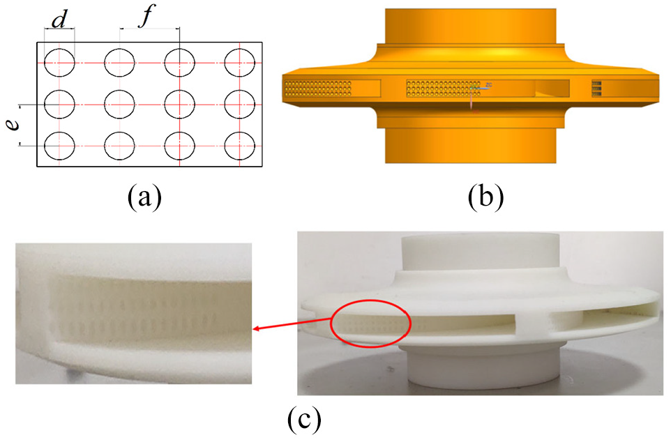
Bionic model: (a) sketch of bionic pit size, (b) part drawing of bionic impeller, and (c) 3D printing of the bionic impeller.
Test system device
The test system mainly includes: circulating water tank, motor, outlet regulating valve, water tank regulating valve, hydrophone, electromagnetic flowmeter, inlet pressure transmitter, outlet pressure transmitter, test pump, TPA, INV3020C acquisition system and computer. The schematic diagram of the test system is shown in Figure 3.
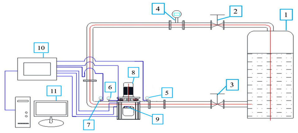
Schematic diagram of test bench.
The test results
The head of the centrifugal pump with smooth blade decreases with the increase of flow while the torque on the impeller increases with the increase of flow. The hydraulic efficiency of the centrifugal pump first increases and then decreases with the increase of head, reaching its maximum value between 1.0Qd and 1.2Qd flow. The hydraulic efficiency under design condition is 73.29%.
The sound pressure level data shows obvious axial frequency APF (49.17 Hz), axial frequency doubling, vane frequency BPF (295 Hz) and vane frequency doubling characteristics. The sound pressure level at axial frequency is 157.41 dB, and that at vane frequency is 154.49 dB. The sound pressure energy is mainly concentrated in the middle and low frequency band below 1200 Hz. The spectrum curve of sound pressure level above 1200 Hz shows a trend of continuous oscillation and decline.
Numerical simulation method
Simulation method
In the “Tianhe-2” supercomputer environment, the numerical calculation of centrifugal pump was carried out by using ANSYS CFX-Linux software. Six working conditions of 0.4Qd, 0.6Qd, 0.8Qd, 1.0Qd, 1.2Qd, and 1.4Qd were set for simulation and analysis. The multi-coordinate system was used in the numerical calculation, in which the impeller water body is set as the rotating domain, the rest of the water body is set as the static region, the boundary conditions are the total pressure inlet, the flow outlet, the fluid medium is 25° clear water, the calculation reference pressure is 0atm, and the rotation speed of the impeller is 2950 r/min. The LES turbulence model is used for unsteady calculation, SMARGORINSKY was selected for Sublattice model, and the convergence criterion was set as RMS average value. The convergence accuracy value is set as 10-4. The K-ε turbulence model is used for steady-state calculation and LES is used for transient calculation.
Grid division
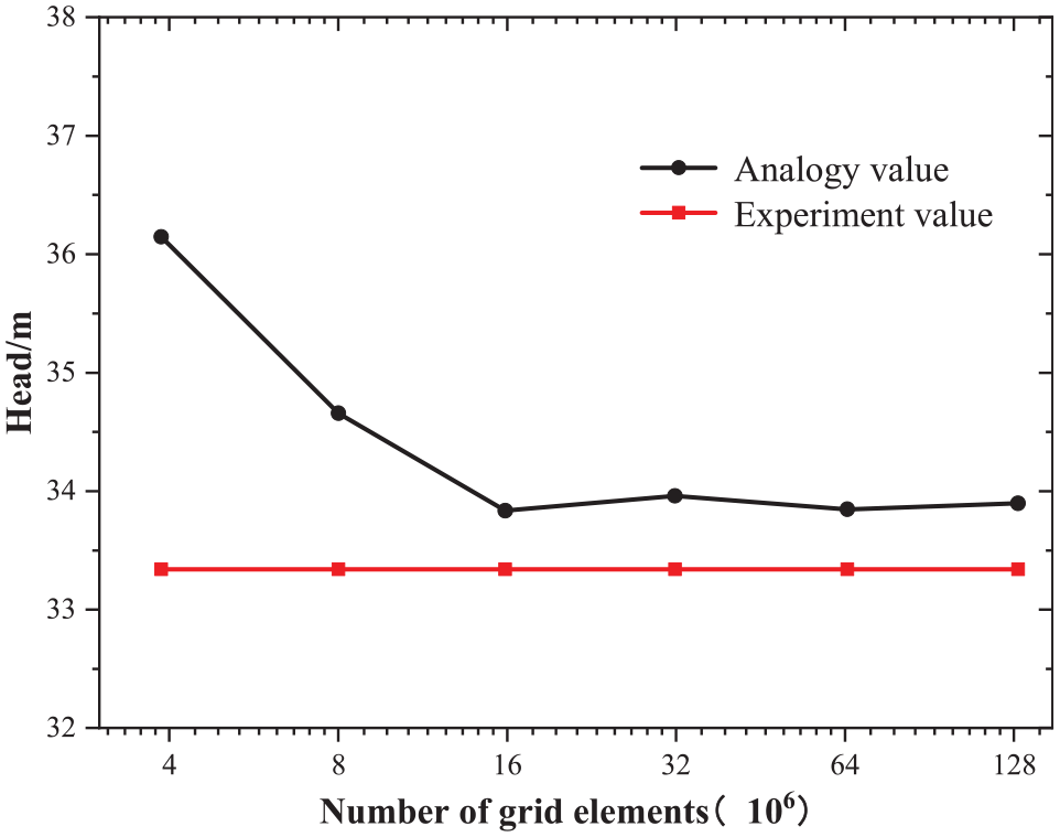
As shown in Figure 4, when the grid number of smooth centrifugal pump exceeds 16 million, the predicted head value starts to stabilize, and the head variation under different grid Numbers is less than 1%. Due to the strict requirements on the wall grid in large eddy simulation, the y+ value of impeller wall can be basically controlled within 1 when the total number of centrifugal pump grids is encrypted to 145.35 million units after repeated intensive calculation. As shown in Figure 5, y+ value on the vane surface is distributed below 1, which meets the requirements of large eddy simulation for wall grid. The mesh details of impeller and vane surface are shown in Figure 6. The mesh quality of the impeller generated by the grid scheme is more than 0.3 and the physical size of the minimum grid unit is less than 0.1 mm, which ensures that there is enough fine mesh on the vane surface.
Head calculation of smooth vane centrifugal pump under different grid elements.

Y+ numerical distribution at the smooth impeller wall.

Grid details of smooth impeller water body and blade wall.
Verification of external characteristics
As shown in Figure 7, the numerical simulation of smooth vane centrifugal pump under different working conditions is compared with the external characteristic curve of the test. It can be seen that the simulated value of head under rated conditions is 33.88 m, the test value of head is 33.34 m, the predicted error of head is 1.6%, and the error between the predicted value and the test results under other conditions is less than 3.5%.Under the rated condition, the predicted efficiency value is 74.92%, the test efficiency value is 71.89%, and the prediction deviation is 4.2%. The deviation between the predicted efficiency and the test value is less than 4.2%. Therefore, the numerical simulation method used in this paper has high accuracy.

Comparison between numerical simulation and experimental characteristics of smooth vane centrifugal pump
Calculation of internal sound field based on volute fixed source
In this paper, Direct boundary element method is used to solve the internal acoustic field. This calculation method is based on LIGHTHILL acoustic analogy method, which can accurately obtain the acoustic characteristics of complex structures under lower frequency excitation. 20 Noise calculation is realized on LMS VIRTUAL.LAB 13.6. In noise calculation, the time-domain pulsation information is transformed into the frequency-domain pulsation information by Fast Fourier Transform, which is mapped to the acoustic grid.21,22 According to the position of hydrophone during the test, the field is set 6 times of pipe diameter away from the pump outlet flange, and the sound pressure level is converted. The acoustic surface grid is shown in Figure 8.

Acoustic surface grid and monitoring points.
Calculation of infield noise
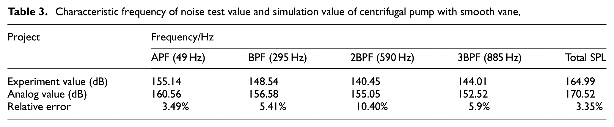
As shown in Figure9, the noise value calculated based on the information of the volute dipole sound source is basically consistent with the trend of the test value. There is a certain difference between the calculated value and the test value on the broadband spectrum below the blade frequency, and the calculated value is lower than the test value. The reason for the error may be that the flow noise actually excited by the inner flow of the centrifugal pump radiates to the inner flow after multiple reflection and scattering on the irregular pipe wall surface. However, the scattering effect of the inner wall of the pipe is ignored in the numerical calculation, so the calculated value is higher at some characteristic frequencies, but lower in some broadband. As shown in Table 3, the maximum error of sound pressure level at the characteristic frequency is no more than 10.4%, and the total error of sound pressure level is also within 3.35%.This shows that the numerical calculation method of the centrifugal pump noise has a certain reliability, and it is feasible to predict the flow noise in the centrifugal pump field qualitatively and quantitatively through the sound source excitation of the volute case dipole. The calculation formula of total sound pressure level

Where

Spectrum of noise test value and simulation value of centrifugal pump with smooth vane.
Characteristic frequency of noise test value and simulation value of centrifugal pump with smooth vane,
Multi-objective optimization design method
Response surface methodology (RSM) is a common design method in optimization design. The accurate relationship between design variables and objectives can be obtained through less experiments and displayed in algebraic form. Then the optimal solution can be obtained according to the equation relationship. The process based on BOX-Behnken design method (BBD) is divided into five steps.
Step 1: Determination of experimental influence factors.
Step 2: Arrange the experiment and get the experimental data.
Step 3: Response surface analysis, using nonlinear fitting to obtain the fitting equation.
Step 4: Using response surface optimization method to obtain the optimal parameters.
Step 5: The optimized parameters are verified by experiments.
Response surface experiment design
The BOX-Behnken design method is used to fit the response surface model. According to the experimental design, three important factors, pit diameter d, axial distance e and radial distance f, are selected to optimize the response surface. According to the biological prototype for similarity analysis, considering the geometric model of the impeller, take the pit diameter d between 0.8 and 1.6 mm, the axial distance e between 1.8 and 2.6 mm, and the radial distance f between 2 and 3 mm.
As shown in Table 4, according to the values of three factors and levels, the BBD method was used to establish the test design table, and a total of 17 groups of test points were generated. The calculation results of different response surface design schemes are statistically summarized. Group 0 represents the calculation results of smooth vane centrifugal pump, as shown in Table 5.
Structural parameter factors and levels.

Test design scheme.

Efficiency optimization model
A regression equation of hydraulic efficiency of the centrifugal pump based on the parameters of each bionic structure can be obtained by using the second order polynomial fitting. The equation is expressed as follows:

The analysis of variance of the fitted regression equation is shown in Table 6. When P value is less than 0.05, it means that the model is significant. The P value of the designed model is 0.0105, which shows that the model fits the whole regression region well. The experimental scheme is set well. The complex correlation coefficient R2 = 0.8947. The experimental model CV = 0.51%. ADEQ precision is the ratio between the effective signal is 9.164. The data show that the efficiency optimization model meets the requirements.
Analysis of variance.

S* indicates extremely significant impact, S indicates significant impact, and NS indicates not significant.
R 2 = 0.8947, CV = 0.51%, ADEQ precision = 9.164.
Noise optimization model
A regression equation of total sound pressure level
The analysis of variance of the fitted regression equation is shown in Table 7. When p value is less than 0.05, the model is significant. The p value of the design model is 0.0007, which shows that the model fits the whole regression region well. The experimental scheme is reasonable. The multiple correlation coefficient R2 = 0.9546. The experimental model CV = 0.31%. ADEQ Precision is the ratio between the effective signal is 14.269. The data show that the noise optimization model meets the requirements.
Analysis of variance.

S* indicates extremely significant impact, S indicates significant impact, and NS indicates not significant.
R 2 = 0.9546, CV = 0.31%, ADEQ precision = 14.269.
Multi-objective optimization model
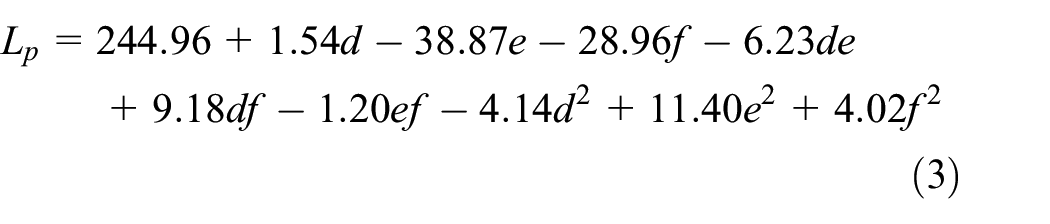
For optimization design, objective function, constraint conditions and design variables are the three important elements. The process of optimization design is to make the design variables reach the optimal solution of the objective function under the condition that the value range of design variables meets the internal constraints. Under the constraints of the optimization design model, the response surface regression equations (2) and (3) of the efficiency and total sound pressure level of the simultaneous centrifugal pump are used to obtain the values of the three influencing factors which make the hydraulic efficiency of the centrifugal pump the highest when the total sound pressure level is lower than the initial smooth vane centrifugal pump. The optimal design model of centrifugal pump operation performance can be expressed as follows:

Where,
Results and discussion
Efficiency optimization results
As shown in Figure 10, when the pit diameter d is 1.2 mm, the axial spacing of bionic pits is between 2 and 2.2 mm, and the radial spacing is between 2.6 and 3 mm, the hydraulic efficiency of centrifugal pump has the highest point. As shown in Figure 11, when the axial distance e is 2.1 mm, the bionic vane centrifugal pump achieves maximum efficiency when the diameter of bionic pit is between 0.8 and 1 mm and the radial distance is between 2.6 and 3 mm. As shown in Figure 12, when the radial spacing f is 2.8 mm, the hydraulic efficiency of bionic vane centrifugal pump can reach a maximum when the axial spacing is between 2 and 2.2 mm regardless of the pit diameter.

Effect of interaction term between axial distance e and radial distance f of pit on efficiency.

Effect of interaction term between pit diameter d and radial spacing f on efficiency.

Effect of interaction term between pit diameter d and axial distance e on efficiency.
Noise optimization results
As shown in Figure 13, when the diameter d of the pit is 1.2 mm, the overall variation range is uniform, and the contour line presents an ellipse with a small radius of curvature, which is close to a circular shape, indicating that the interaction between axial spacing and radial spacing of bionic pits is not significant. As shown in Figure 14, when the axial distance e is 2.1 mm, the best noise reduction effect point is that the pit diameter d is 0.8 mm, and the radial distance f is between 2.6 and 3 mm. As shown in Figure 15, when the radial spacing f is 2.8 mm, the total sound pressure level of bionic vane centrifugal pump reaches a minimum when the axial spacing is between 2 and 2.4 mm regardless of the pit diameter.

Interaction between axial distance e and radial distance f of pits on total sound pressure level.

Interaction of pit diameter d and radial spacing f on total sound pressure level.

Interaction of pit diameter d and axial distance e on total sound pressure level.
Multi-objective optimization results
According to the multi-objective optimization model, the values of the three parameters are d = 0.80 mm, e = 2.11 mm, f = 2.91 mm. After response surface optimization, the predicted maximum efficiency of centrifugal pump is 78.29%, and the predicted value of total sound pressure level is 165.58 dB. As shown in Table 8, under the rated flow rate, the error between the predicted value and the simulation value by using response surface is less than 0.5%, so the optimized parameter variables have sufficient credibility. Compared with the results of several schemes in Table 4, the efficiency of smooth centrifugal pump is increased by 3.2 percentage points, and the efficiency increase rate reaches 4.27%. At the same time, the total sound pressure level of the centrifugal pump is reduced by 5.19 dB, and the noise reduction rate is 3.03%. Compared with the efficiency enhancement rate of 3.08% and the noise reduction rate of 2.13% under the rated condition before optimization, the efficiency and noise reduction rate of bionic centrifugal pump after multi-objective optimization are significantly improved. Therefore, according to the results of numerical simulation, the multi-objective optimization method based on response surface method has high prediction accuracy, and has obvious synergistic effect on hydraulic performance and acoustic performance of centrifugal pump.
Comparison and verification of response surface optimization results.

Analysis of hydraulic performance test results
As shown in Figure 16, the hydraulic performance curve of the optimized bionic vane and smooth vane centrifugal pump is compared. It can be seen from the figure that the bionic vane has little influence on the centrifugal pump head, only 0.59 m is increased under the design flow. With the increase of flow rate, the optimization of torque and hydraulic efficiency of bionic blade becomes more and more obvious. When the flow rate is 1.2Qd, the drag reduction rate reaches the maximum value of 3.03%, and the efficiency increase rate is 4.41%. The optimized external characteristic curve makes the maximum efficiency point shift to the direction of large flow, which effectively widens the efficient working area of centrifugal pump. Under the condition of larger flow rate than 0.8Qd, the hydraulic efficiency increases by 2.55%. Under the rated condition, the drag reduction rate is 2.13%, the hydraulic efficiency of centrifugal pump is increased from 71.89% to 74.92%, which is 3.03% higher, and the efficiency increase rate is 4.21%. Therefore, by optimizing the bionic structural parameters of the blade, the bionic pit applied to the centrifugal pump blade can significantly improve the hydraulic performance of the centrifugal pump.

Test value curve of hydraulic performance of centrifugal pumps with different vanes.
Analysis of field noise test results
As shown in Figure 17, the variation trend of flow noise spectrum in centrifugal pump under different working conditions is basically the same, with obvious shaft frequency, shaft frequency doubling, blade frequency and blade frequency doubling characteristics in the middle and low frequency band below 1200 Hz. It is found that the sound pressure level of the optimized centrifugal pump decreases to a certain extent at the wide frequency band and each characteristic frequency.

Noise test spectrum at the outlet of centrifugal pump with different vanes.
In order to quantitatively analyze the noise reduction effect of the optimized bionic vane centrifugal pump, the sound pressure levels and their change rates at different eigenvalues are listed. As shown in Table 9, the total sound pressure level of centrifugal pump is reduced by 4.32–5.39 dB under different working conditions, and the sound pressure level of centrifugal pump with blade frequency up to three times is reduced by 1.89%–4.02%. Under the rated condition, the total sound pressure level is the smallest, the total sound pressure level decreases from 164.99 to 160.03 dB, the total sound pressure level decreases by 4.96 dB, and the noise reduction rate reaches 3.01%. Therefore, the blade optimized by response surface method can not only effectively improve the hydraulic performance of the centrifugal pump, but also synergistically optimize the internal field noise of the centrifugal pump, so that the comprehensive performance of the centrifugal pump is significantly improved.
Sound pressure level and its change rate at characteristic value of centrifugal pump.

Summary
Based on the response surface method and numerical simulation, the multiple regression equation of the influence of key parameters of bionic vane on the hydraulic efficiency and total sound pressure level of centrifugal pump was established. A multi-objective optimization model was established to improve the efficiency and acoustic characteristics of centrifugal pump. The external characteristics and internal noise of centrifugal pump before and after optimization were compared and analyzed by experiments. The results show that:
Three important geometric parameters of blade bionic structure were selected and 17 experimental schemes were designed by using BBD method. The multiple regression equation of each parameter with hydraulic performance and noise characteristic of centrifugal pump is established. The analysis of variance showed that the regression equation fitted the prediction well and could reflect the correlation between parameters and response values.
A multi-objective optimization model of the efficiency and acoustic characteristics of the centrifugal pump was established. Combined with the multiple regression equation between parameters and objectives, the multi-objective optimization parameters were obtained as follows: pit diameter d = 0.80 mm, pit axial spacing e = 2.11 mm, and pit radial spacing f = 2.91 mm.
After comparing and analyzing the results before and after the optimization, it is found that the hydraulic efficiency is increased by 3.03% and the drag reduction rate is 2.13% under rated conditions. The maximum efficiency point of the optimized centrifugal pump is shifted to the direction of large flow. The sound pressure level decreased to some extent, and the total sound pressure level decreased by 4.96 dB under the design condition.
Footnotes
Appendix I
Handling editor: James Baldwin
Declaration of conflicting interests
The author(s) declared no potential conflicts of interest with respect to the research, authorship, and/or publication of this article.
Funding
The author(s) disclosed receipt of the following financial support for the research, authorship, and/or publication of this article: This work was supported by National Natural Science Foundation of China (No. 51879122, 51579117, 51779106), National Key Research and Development Program of China (Grant No. 2016YFB0200901, 2017YFC0804107), Zhenjiang key research and development plan (GY2017001, GY2018025), the Open Research Subject of Key Laboratory of Fluid and Power Machinery, Ministry of Education, Xihua University (szjj2017-094, szjj2016-068), Sichuan Provincial Key Lab of Process Equipment and Control (GK201614, GK201816), Jiangsu University Young Talent training Program-Outstanding Young backbone Teacher, Program Development of Jiangsu Higher Education Institutions (PAPD), and Jiangsu top six talent summit project (GDZB-017).