
Abstract
In order to reduce the oil consumption, the vehicle in the process of in-situ shift should be quick enough, but the vibration and shock of the vehicle will be deteriorate. Then the effect of a novel semi-active hydraulic damping strut (HDS) on vehicle shock and vibration in the process of in-situ shift quickly in this study is analyzed. Firstly, the shift shock is analyzed from the driver system, and the powertrain mounting system (PMS) is regarded as the object to be optimized in this study. Then the 13 degree of freedoms (DOFs) vehicle dynamic model (VDM) with semi-active HDS is presented in this paper. The excitation force in the process of quick in-situ shift is identified, and the evaluation indexes (EIs) are reduced with semi-active HDS introduced. Finally, the experiments are carried out to validate the effect of the semi-active HDS on vehicle longitudinal vibration and shock in the process of quick in-situ shift, and the results show that the acceleration of the seat rail and steering wheel are reduced to a great extent. Different shift time is discussed and the results show that we can reduce the shift time to save the oil with semi-active HDS introduced.
Keywords
Introduction
The control of the oil consumption in vehicles is significant for conserving energy and reducing emission. In order to reduce engine fuel consumption, the engine start and in-situ shift process should be quick enough for traditional fuel vehicle. However, the vibration and shock of the vehicle will be deteriorate if the in-situ shift time is reduced. Therefore, reducing the in-situ shift time without destroy the vehicle noise, vibration and harshness (NVH) performance is essential and meaningful.
At present, there are two methods to reduce the shift shock and vibration: (1) take the optimal control algorithm to make the shift smoothly; (2) design and optimize the PMS. However, the compensation control or optimization control strategy often depends on the precision of the control system on transient conditions. 1
For the traditional four-cylinder internal combustion, the solution to reduce the up-shift shock is taken some optimization control algorithms to control the clutch or brake hydraulic oil pressure and function time in torque or inertia phase.2,3 As for the diesel engine, the measure for reducing down-shift shock is to take turbine acceleration or speed as a reference model to work out control strategy to improve shift quality.4,5 Walker and Zhang 6 presented an active control strategy for the suppression of gear shift related transient vibrations, and the results show that the importance of inertia phase on minimizing powertrain vibration during and after shifting. Lin et al. 7 developed an optimal feedback controller to interrupt power input and prevent the driveline from torsional vibration by controlling the torque input actively when shifting. Simulation results demonstrate the optimal control of motor torque can reduce torsional vibration in driveline significantly. Roozegar and Angeles8,9 proposed a two-phase control algorithm for gear-shifting in a novel multi-speed transmission as to electric vehicles (EVs), and the results demonstrate that the proposed approach is promising for a smooth and swift gear-shifting in EVs. Tian et al. 10 used the longitudinal vehicle jerk and shift time as the evaluation metrics for the gear shifting control of a novel two-speed transmission as for the battery electric vehicles.
There are few reports on reducing the shock and vibration of the vehicle in the process of in-situ shift. The dynamic model-based feedback control approaches based on the information of vehicle parameters and dynamics can be adopted to reduce the vehicle in-situ shift shock and vibration.11,12 Tao et al. 13 proposed the method of online evaluation in launching process to improve the launching quality and give the refining direction of the control parameters. Nessler and Stokes 14 analyzed that the vehicle in-situ shift vibration can be reduced by increasing the fore-aft stiffness or decreasing the vertical stiffness of the mount in the PMS. Naruse and Kuno 15 pointed out that mounts have a great effect on vehicle shock and vibration in the process of gear shifting. Arruda et al. 16 highlighted that the mounting system has a great effect on the person’s subjective feeling.
As the shift time is short, the key parameters to reduce shock and vibration when vehicle is in the process of in-situ shift quickly may be hard to identify from the point of vehicle driving system, and adjust the mount system stiffness will destroy the vibration isolation performance at engine idle speed. Therefore, a semi-active control method is used in this paper to add temporary larger damping into the PMS to analyze the vibration attenuation law in the process of vehicle in-situ shift with different shift time. The remainder of this paper is organized as follows: Section 2 analyzes the principle of shift shock and the methods to reduce the shock. Section 3 the dynamic response evaluation indexes (DREIs) are calculated and analyzed with and without semi-active HDS based on 13 DOFs VDM. Section 4 some works on experiments are carried out and the experiment results are analyzed. Section 5 discusses the shift shock with different shift time. Finally, Section 6 draw conclusions.
Shift shock and solution analysis
Shift shock analysis
As for the vehicle equipped with AT (auto transmission) in this study, the model of the vehicle driver system is shown in Figure 1, and the shift process is accomplished by the separation or combination of the actuators (clutch C1, C2, and F, brake B1, B2, and B3). The shift shock of the vehicle with AT comes from the following three aspects: (1) improper matching of actuating mechanism (clutch and brake) in shifting process; (2) the output transmission torque fluctuation caused by clutch or brake torque in shifting process; (3) the sudden change of the transmission ratio makes the speed difference of the main gear and the driven gear become bigger, thus it is easy to produce shock in the synchronous process.

Vehicle driver system.
It can be seen that the dynamic model of the vehicle in shifting process consists of the engine, torque converter, planetary transmission, final drive, the wheel axle, tires and vehicle body, the clutches (C1, C2, and F) and brakes (B1, B2, and B3), as shown in Figure 1.
The output torque of the transmission can be described as:

Where Tout and Tin are the output and input torque of transmission, respectively. iT is the transmission ratio of target gear, Tb, Tc, and Tg are the resistant torque of brake, clutch and gear synchronization in the process of the gear shifting, respectively. α, β, and γ are the brake, gear, and the clutch contact ratio, respectively, and the value is between 0 and 1.
The clutch and brake torque can be described as equations (2) and (3), respectively. 17 Meanwhile, the friction coefficient is expressed as the function of the static friction coefficient and the dynamic friction coefficient. 18


Where ΔV is the relative velocity of the clutch plates, A is the contact area, P is the control pressure, N is the number of plates, Ro is the inner radius of the plates, Ri is the outer radius of plates, Fa is the control force, RD is the radius of plates, λ is the contact angle, Vcirt is the constant of the clutch friction characteristics. μ, μs, and μk are the friction coefficient, static friction coefficient, and dynamic friction coefficient, respectively.
In the process of the gear shifting, the driving and driven gear has greatly angular speed difference, thus the meshing force in the gear synchronization process can be written as:
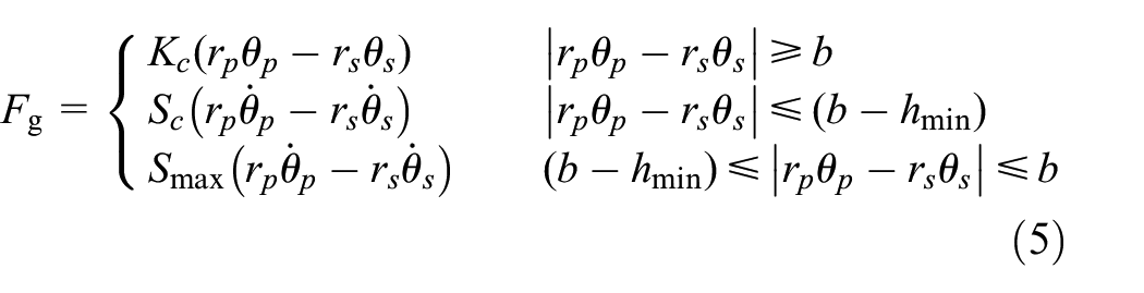
Where Kc represents the meshing stiffness of gear pair, Sc represents the equivalent oil film damping coefficient, hmin is the minimum film thickness and the value of hmin can be seen in Brancati et al., 19 b is the blackness, the relative displacement between the gear teeth and can be calculated by rpθp–rsθs. If the absolute value of the rpθp–rsθs is less than or equal to b, then the clearance exists and the oil film damping force is produced, otherwise the gear pair is in the meshing state.
The equivalent oil film damping coefficient is described as follows: 20


Where δ is relative displacement between meshing gears, τ is dynamic viscosity of lubricating oil, ω is addendum of the gear, b is the engagement clearance of one side, δ is the relative displacement.
Then the meshing torque Tg in the gear synchronization process is:

Take the shifting process from park state to drive state as example, the working principle is as follows: The sun wheel of the planetary gear set 1 (P1) rotates in clockwise direction, the planet wheel rotates in counter clockwise direction, and the ring gear is locked because of the function of the one way clutch F. Thus the planet carrier makes the ring gear of planetary gear set 3 (P3) rotate in clockwise direction, and the planet wheel and sun wheel of the planetary gear set 3 rotates in clockwise direction and in counter clockwise direction, respectively. Therefore, there is no torque generated owing to the free rotation of the P3 parts. As the transmission is shifted from P state to D state, the sun wheel of the P3 is locked because of the function of the brake B3. So the planet carrier rotates in clockwise direction and generates the same direction torque.
The parameters of the Tb, Tg, and Tc have strong nonlinear characteristics in the process of in-situ shift, and the identification of the parameters are difficult because of the driver system is not fully connected in this process. Meanwhile, it is difficult to analyze the dynamic response characteristics in the process of in-situ shift according to vehicle driving system. Therefore, it is hard to reduce the vehicle in-situ shift vibration and shock from the point of the driver system, especially the shift time is reduced.
Solution analysis
The powertrain is consisted of the engine, torque converter, planetary transmission, which the first mode is larger than 60 Hz based on engineering experience. The vehicle is at stationary state when vehicle in the process of in-situ shift, and the vibration frequency caused by shift shock is less than the first mode of the powertrain, thus the powertrain can be regarded as a rigid body. Since the vehicle in-situ shift vibration can be attributed to the sudden change of torque in the powertrain because of the torque disturbance in the transmission. Therefore, the vibration of the vehicle in-situ shift can be reduced by the optimum design of the PMS, then the vibration can be reduced from the powertrain to the vehicle interior.
According to previous study, 21 the vehicle vibration in transient events can be reduced effectively with damping introduced in the PMS. Thus a novel semi-active HDS is used in the PMS, as shown in Figure 2. The semi-active HDS is installed between the engine and sub frame in the PMS, which provides larger damping to reduce shock and vibration of the vehicle in low frequency range with solenoid valve energized, and isolate the engine high-frequency vibration without solenoid valve energized, as shown in Figure 3.

The structure of the semi-active HDS.

The four points PMS.
The dynamic stiffness and damping coefficient of the semi-active HDS with different amplitude and frequency are tested with MTS 831, as shown in Figures 4 and 5. 22 It can be seen that the larger damping can be obtained in low frequency band to reduce the shock and vibration when vehicle is in the process of in-situ shift.

Dynamic stiffness of semi-active HDS with different amplitudes: (a) solenoid valve without energized, and (b) solenoid valve energized.
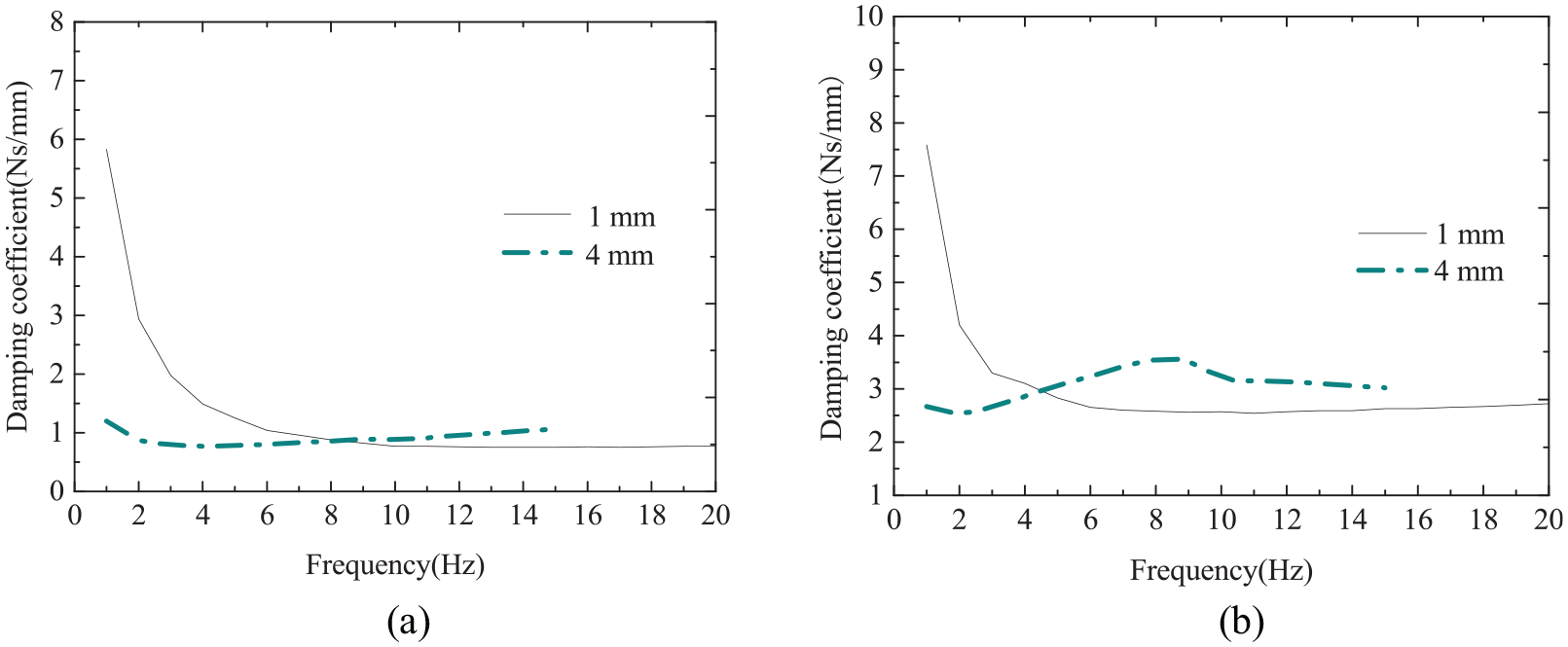
Damping coefficient of semi-active HDS with different amplitudes: (a) solenoid valve without energized, and (b) solenoid valve energized.
The installation position of the semi-active HDS is determined according to design method of the PMS. 23 The optimized dynamic characteristic parameters of the semi-active HDS in the process of in-situ shift 24 are taken to analyze the vehicle dynamic response when vehicle is in the process of in-situ shift quickly.
13 DOFs VDM and dynamic response analysis
13 DOFs VDM
A 13 DOFs VDM is built in order to analyze the influence of semi-active HDS on vehicle vibration response, which include the tyres, suspension, unsprung mass, vehicle body and the PMS. The 13 DOFs VDM with semi-active HDS is shown in Figure 6.

13 DOFs VDM with semi-active HDS.
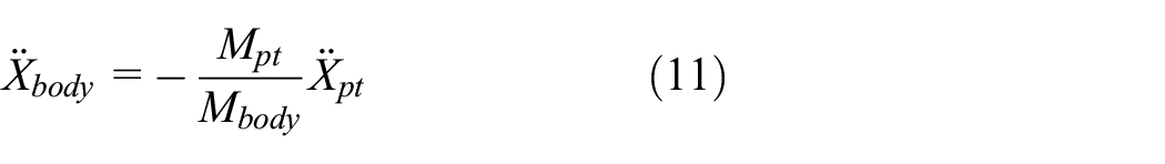
Under engine excitation, the vertical displacement of the unsprung mass, the CoG (center of gravity) of the PMS and vehicle body can be described as:

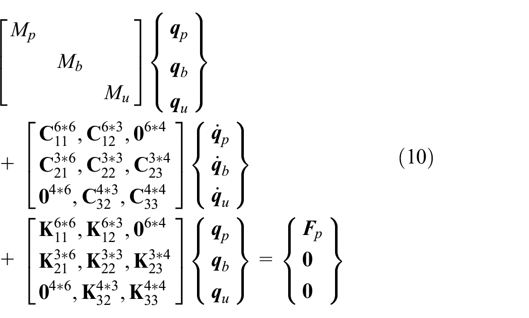
When vehicle is in the process of in-situ shift, the excitation force can be attributed to the powertrain, and the vibration equation of the vehicle 13 DOFs dynamic model in the process of in-situ shift can be written as equation (10). The meaning of the related parameters can be obtained according to previous study. 21
Evaluation index
In order to evaluate the dynamic response of the vehicle in the process of in-situ shift, the following evaluation indexes are proposed:
Shift time
A shift process that takes longer time will cause the fuel consumption to be increased. However, the shock and vibration of the vehicle will be aggravated with the shift time reduced. 25 Therefore, an optimized shift time with small vibration and shock is meaningful.
Vehicle acceleration
The vehicle acceleration is correlated with output torque fluctuation of the powertrain, and big torque fluctuation will result in larger vibration in longitudinal direction.
Jerk
The derivative of acceleration in longitudinal direction has been used to define the shift quality, and a smooth shift means that the vehicle has smaller vibration.

VDV (Vibration Dose Value)
VDV is used to quantify human feeling in a transient event, 26 and the value is proportional to the driver’s sensation:

Seat rail acceleration
The seat rail acceleration is an objective evaluation index, which is acquired by experiment test. The peak acceleration value can be used to evaluate the vehicle vibration in the unstable states.
Dynamic response analysis
Reducing the shift time not only saves fuel consumption but also reduces the sliding time of friction components, and the accumulated friction loss is reduced as well. However, the rapid shift process inevitably cause greater vehicle shock and dynamic load, the vehicle body vibration is increased, which makes the vehicle ride comfort become worse.
In order to analyze the influence of the semi-active HDS on the vibration of the vehicle when in-situ shift quickly, the shift time is changed from 1.2 s to 0.9 s in this study, which is 1.2 s in previous study, 24 and the 13 DOFs VDM is used to analyze the DREIs with and without semi-active HDS. The acceleration and dynamic reaction force at the mount active side are obtained through the test, as shown in Figures 7 and 8.

Mount system dynamic reaction force: (a) X axis, (b) Y axis, and (c) Y axis.

Mount system acceleration: (a) engine mount, (b) transmission mount, and (c) torque strut.
The identified excitation force results are acquired according to mount deformation theory and Newton’ second law, as shown in Figure 9:

Excitation force: (a) force, and (b) torque.
In order to evaluate the influence of the semi-active HDS on vibration and shock of vehicle in the process of in-situ shift quickly, the DREIs such as the longitudinal and vertical acceleration, vehicle body jerk, the active side VDV of the mount with and without semi-active HDS are analyzed using the 13 DOFs VDM according to the related parameters.
The longitudinal acceleration and vertical acceleration in frequency band for vehicle body are shown in Figures 10 and 11 respectively with and without semi-active HDS introduced. The vibration frequencies of the acceleration in longitudinal and vertical direction are 4 Hz, 9 Hz, and 25 Hz, respectively, and these vibration frequencies are related to the excitation frequency of the engine to a great extent. The acceleration in longitudinal and vertical acceleration of the vehicle are reduced in all frequency ranges with the semi-active HDS introduced.
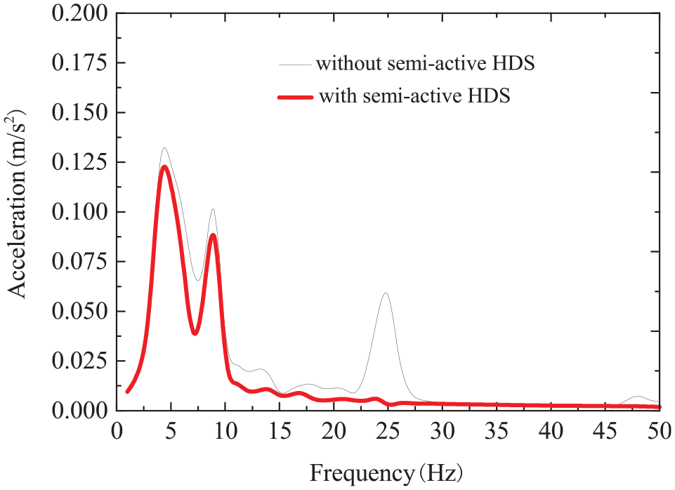
Longitudinal acceleration spectrum.

Vertical acceleration spectrum.
The jerk in frequency band with and without semi-active HDS are shown in Figure 12, which shows that the maximum value of the vehicle jerk without semi-active HDS is 12.2 m/s3 for the vehicle body. The maximum jerk is 4.93 m/s3 in low frequency ranges with the semi-active HDS introduced, which is less than 10 m/s3. Therefore, the NVH performance of the vehicle is improved with semi-active HDS introduced.
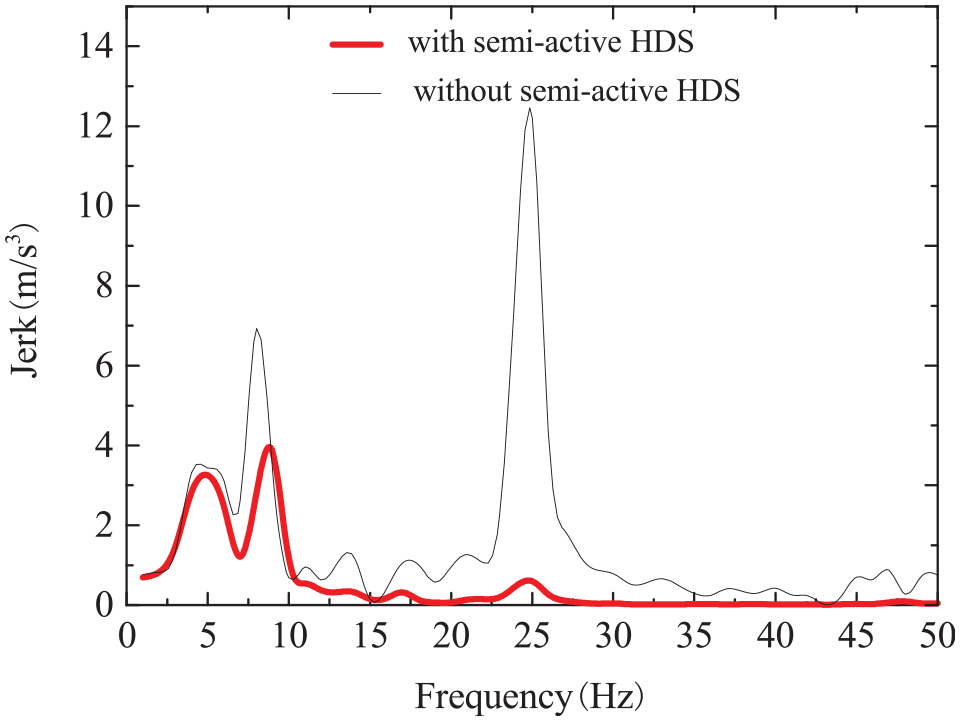
Vehicle body jerk.
The mount system VDV values with and without the semi-active HDS are shown in Figure 13, the peak value of the VDV is reduced from 1.95 ms−1.75 to 1.77 ms−1.75 for engine mount, and the peak value of the VDV is decreased from 3.14 ms−1.75 to 2.56 ms−1.75 for torque strut, which is reduced by 9.2% and 18%, respectively. The peak value of the transmission VDV is reduced from 1.64 ms−1.75 to 1.62 ms−1.75. Therefore, the active side accelerations of the mount system are reduced when the semi-active HDS is introduced, thus the vibration transmitted from sub frame to vehicle body is reduced.
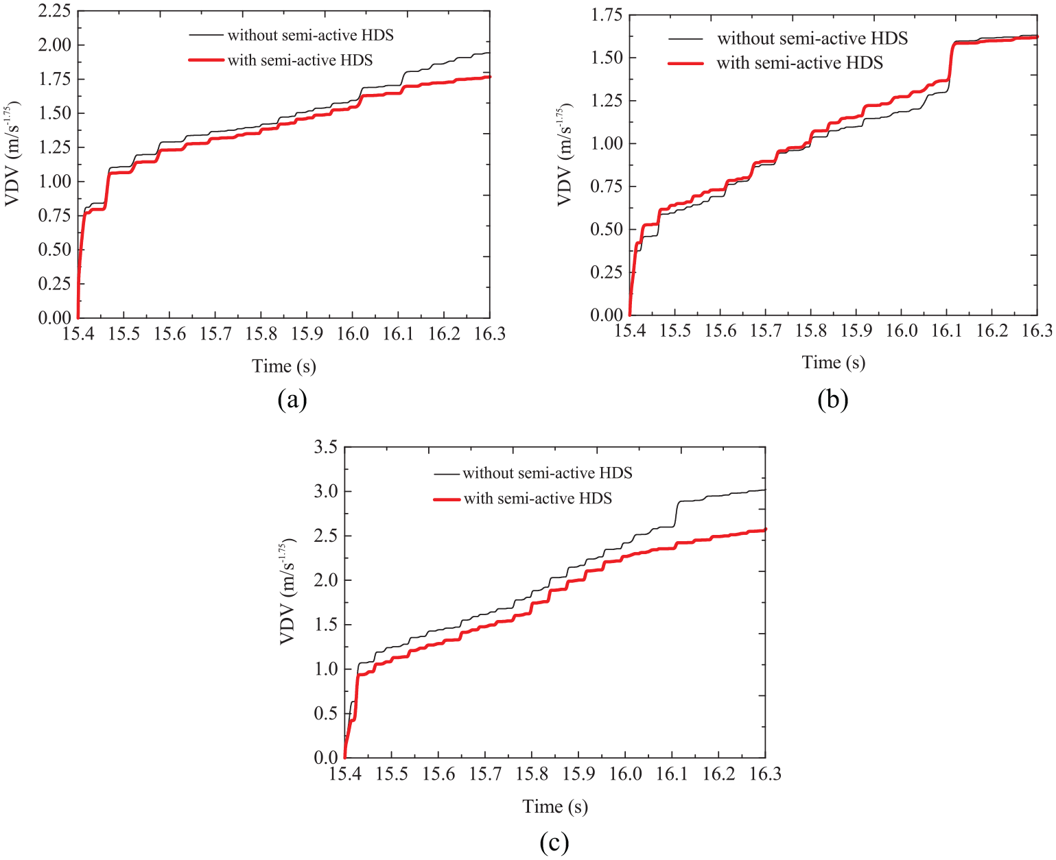
Mount system VDV: (a) engine mount, (b) transmission mount, and (c) torque strut.
Experiment
In order to validate the effect of the semi-active HDS on vehicle in-situ shift quickly, the accelerations of the seat rail and the steering wheel are obtained by LMS data acquisition equipment and tri-axial micro acceleration sensor, and the shift time is calibrated as 0.9 s.
When the vehicle is shifted from P state to D state and then from D state to P state at a static state, the acceleration of the seat rail in three directions with and without semi-active HDS are shown in Figures 14 and 15.
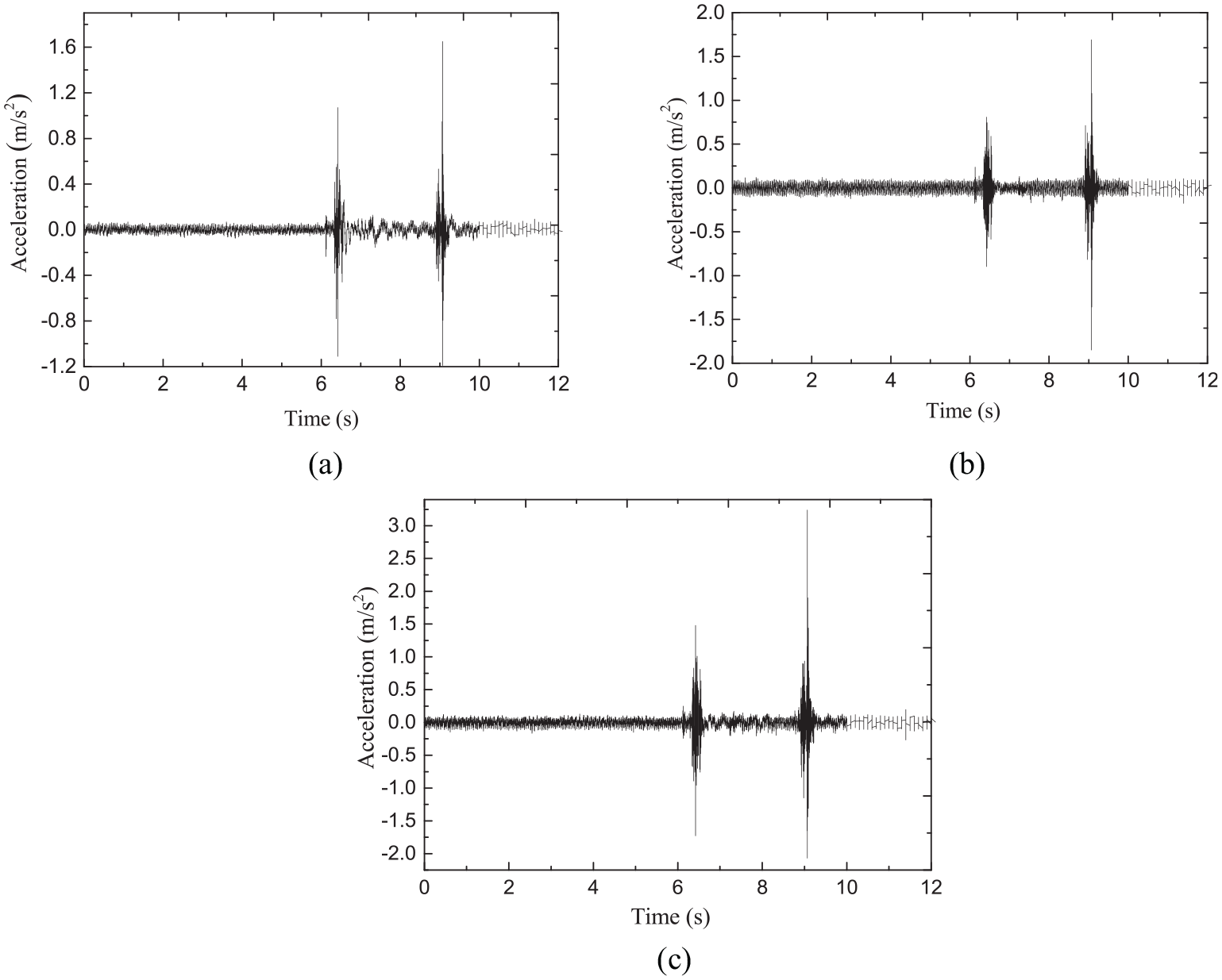
Seat rail acceleration without semi-active HDS: (a) X direction, (b) Y direction, and (c) Z direction.
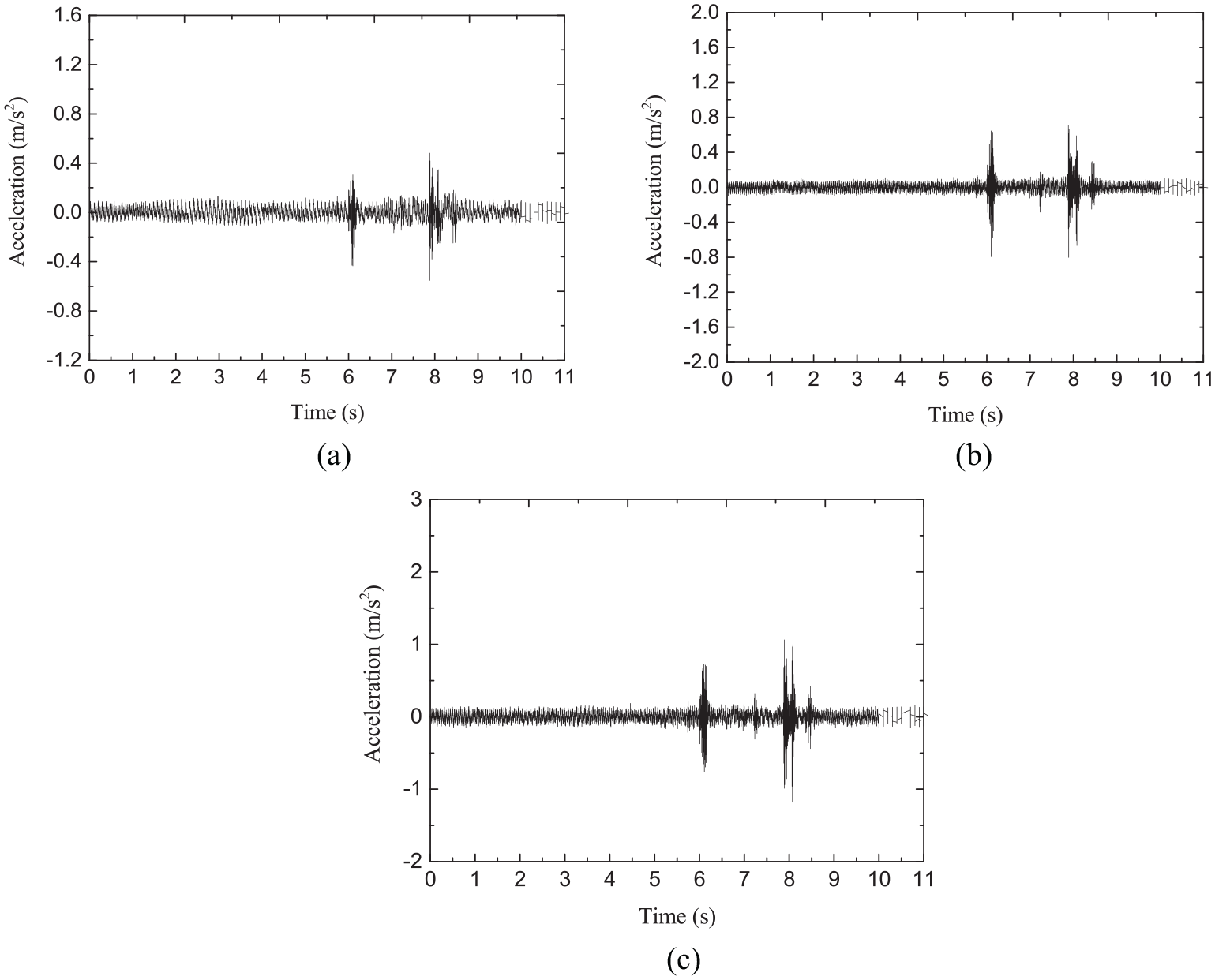
Seat rail acceleration with semi-active HDS: (a) X direction, (b) Y direction, and (c) Z direction.
The acceleration of the steering wheel in three directions with and without semi-active HDS are shown in Figures 16 and 17:

Steering wheel acceleration without semi-active HDS: (a) X direction, (b) Y direction, and (c) Z direction.

Steering wheel acceleration with semi-active HDS: (a) X direction, (b) Y direction, and (c) Z direction.
The peak acceleration value of the seat rail and steering wheel in three directions are shown in Table 1 when shifted from P state to D state quickly.
P to D process.

Table 1 shows that when the AT is shifted from P state to D state quickly, the peak values of seat rail acceleration in X, Y, and Z direction are reduced by 70%, 11%, and 55% respectively with the semi-active HDS introduced. Meanwhile, the peak values of steering wheel acceleration in X, Y and Z direction are reduced by 21%, 21%, and 4%. It can be seen that the seat rail acceleration in longitudinal direction is reduced to a great extent with the semi-active HDS introduced, which the human being is sensitive to the vibration in this direction. 27 The steering wheel acceleration in Z direction is changed little, so the semi-active HDS can’t effectively suppress vibration and shock of the vehicle in the Z direction.
The peak acceleration value of the seat rail and steering wheel in three directions are shown in Table 2 when shifted from D state to P state quickly.
D to P process.
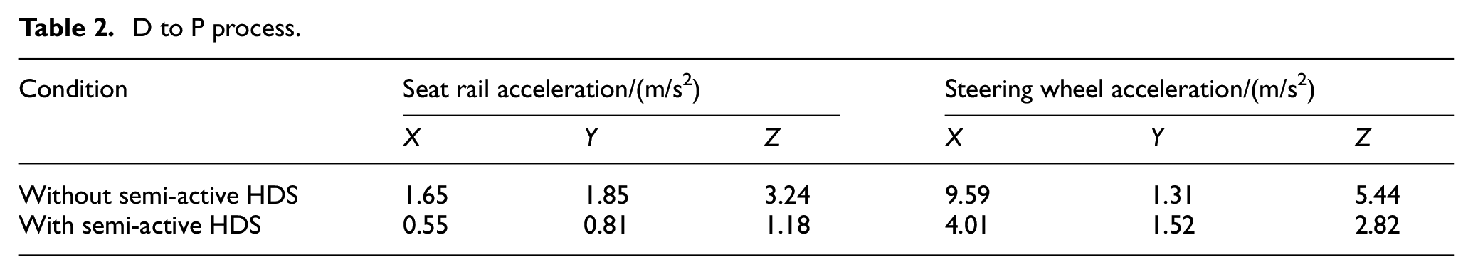
Table 2 shows that when the AT is shifted from D state to P state quickly, the peak values of seat rail acceleration in X, Y, and Z direction are reduced by 67%, 56%, and 63.6%, respectively with the semi-active HDS introduced. Meanwhile, the peak values of steering wheel acceleration in X and Z direction are reduced by 58% and 48%, whereas the acceleration in Y direction is increased by 16%. However, the human being is not sensitive to the vibration in Y direction compared with the vibration in X and Z direction. Therefore, the acceleration of the seat rail and steering wheel are reduced to a great extent in all directions when vehicle is shifted from D state to P state quickly, and the results of the vibration suppression is obvious compared with vehicle shifted from P state to D state.
Discussion
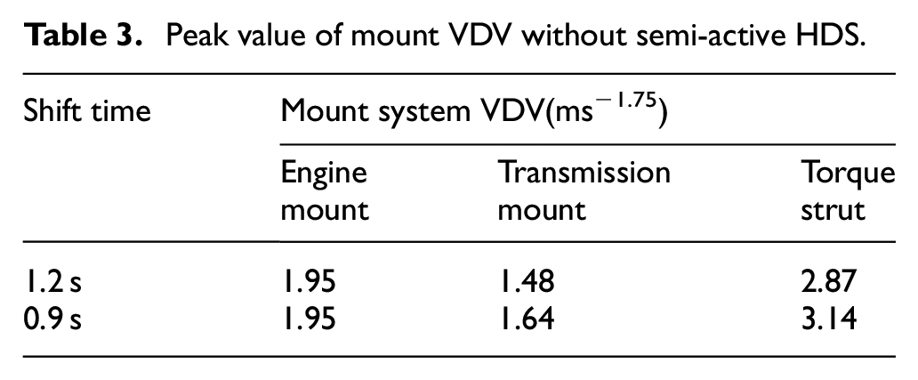
When the shift time is reduced from 1.2 s to 0.9 s, the calculated peak VDV values with and without semi-active HDS are showed in Tables 3 and 4:
Peak value of mount VDV without semi-active HDS.
Peak value of mount VDV with semi-active HDS.
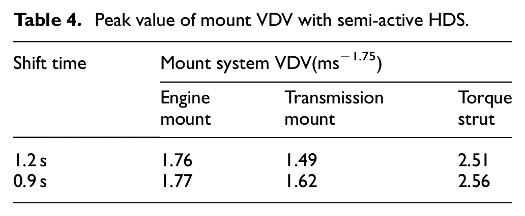
It can be seen that the peak VDV values of the engine mount are changed little compared with the transmission mount and torque strut for different shift time with and without the semi-active HDS, as shown in Tables 3 and 4. The peak VDV values of the transmission mount and torque strut are increased when the shift time is reduced. Therefore, it can be concluded that the vehicle vibration is transmitted by the transmission mount and torque strut with and without the semi-active HDS for different shift time.
As shown in Tables 3 and 4, it can be seen that the peak VDV values of the engine mount are reduced by 10% and 9.2% when the shift time is 1.2 s and 0.9 s, respectively, the peak VDV values of the torque strut are reduced by 12.5% and 18% with and without the semi-active HDS respectively. However, the peak VDV values of the transmission mount is changed little with and without the semi-active HDS. Therefore, it can be seen that the transmission mount is not sensitive to the damping added in the PMS, and the semi-active HDS can effectively reduce the transient shock.
Furthermore, the dates of the Table 4 convey that the vehicle vibration is primary transmitted by the transmission mount, and then the vibration is transmitted by torque strut. The engine mount is not sensitive to the increased vibration as to the reduced shifting time.
The seat rail acceleration of the vehicle shifted from P state to D state with and without semi-active HDS are shown in Tables 5 and 6:
Seat rail acceleration from P state to D state without semi-active HDS.

Seat rail acceleration from P state to D state with semi-active HDS.

As shown in Tables 5 and 6, it can be seen that the seat rail acceleration is increased to a great extent when the shift time is reduced from 1.2 s to 0.9 s. The seat rail accelerations are reduced greatly in Z direction with semi-active HDS introduced for different shift time based on Tables 5 and 6. What’s more, when the shift time is 0.9 s, the seat rail accelerations with semi-active HDS introduced are approximately equal to the values without semi-active HDS introduced when the shift time is 1.2 s. Therefore, we can reduce the shift time to save the oil with semi-active HDS introduced.
The seat rail acceleration of the vehicle shifted from D state to P state with and without semi-active HDS are shown in Tables 7 and 8:
Seat rail acceleration from D state to P state without semi-active HDS.

Seat rail acceleration from D state to P state with semi-active HDS.

As shown in Tables 5 to 8, it can be seen that when the vehicle is shifted from D state to P state, the seat rail accelerations on the whole are larger than shifted from P state to D state with semi-active HDS introduced for different shift time, which attributed to the nonlinear properties of the vehicle system.
The sear rail accelerations in X, Y, and Z direction are reduced greatly when the shift time is 0.9 s and 1.2 s respectively according to Tables 7 and 8 with semi-active HDS introduced. Meanwhile, when the shift time is 0.9 s, the seat rail accelerations with semi-active HDS introduced are less than the values without semi-active HDS introduced when the shift time is 1.2 s as well. We can reduce the shift time to save the oil with semi-active HDS introduced based on above analysis.
Conclusion
A novel semi-active HDS is taken in the PMS to reduce the vehicle in-situ shift quickly based on the discussion of the shift shock from the vehicle driver system. All the evaluation indexes such as acceleration, jerk and VDV are reduced to some extent when the semi-active HDS is introduced.
The experiments are carried out and the acceleration of seat rail and steering wheel in three directions are measured. The results show that when the vehicle is in the process of P-D-P quickly, the acceleration of the seat rail and steering wheel are reduced to a great extent in all directions, and the vibrations that the human being is likely to feel are reduced by 70% and 67% when shifted from P state to D state and then from D state to P state. Meanwhile, when the vehicle is shifted from D state to P state, the vibration suppression effect is better compared with vehicle shifted from P state to D state.
It can be concluded that the vehicle vibration is transmitted by the transmission mount and torque strut when vehicle is in the process of in-situ shift with different shift time. The transmission mount is not sensitive to the damping added in the PMS, and the engine mount is not sensitive to the increased vibration as to the reduced shifting time. When the shift time is 0.9 s, the seat rail accelerations with semi-active HDS introduced are less than the values without semi-active HDS introduced when the shift time is 1.2 s, thus the semi-active HDS can effectively reduce the vehicle transient low-frequency vibration and shock. What’s more, the shift time can be reduced to save the oil with semi-active HDS introduced.
Footnotes
Handling Editor: James Baldwin
Declaration of conflicting interests
The author(s) declared no potential conflicts of interest with respect to the research, authorship, and/or publication of this article.
Funding
The author(s) disclosed receipt of the following financial support for the research, authorship, and/or publication of this article: This research was supported by the youth innovative talents program of Guangdong education department [No. 2018KQNCX282] and basic and applied research in Guangdong province [No. 2019A1515110584].