
Abstract
Stern tube seals are a key component of the propulsion system of a ship. The purpose of these sealing rings is to ensure a reliable sealing condition, preventing the spillage of lubricant to the environment. The research on these large rotary seals is limited due to their complex accessibility: stern tube seals are located below the seawater level on a moving ship. A dynamic setup replicating the operating conditions of a stern tube seal is presented together with a novel arrangement for monitoring the flow rate across the seal. The frictional torque, the operating temperature, and the lubricant migration across the seal are measured under various shaft velocities and pressure differences. The existing theory for rotary lip seals is reviewed for the stern tube seal application. From the results it is deduced that the stern tube seals tested operate within the elastohydrodynamic regime with film thicknesses in the sub-micrometer range.
Introduction
The propulsion system of a vessel is a critical part of a ship because it is subject to maintenance and crucial for the operation of the ship. The propulsion shaft goes through a metal cylinder welded onto the hull connecting the engine chamber to the stern of the ship, namely the stern tube. Within this tube, the stern tube bearings carry the weight of the shaft while allowing for its rotation. The entire stern tube is flooded with lubricant in order to minimize the friction on the bearings, so the engine power is used primarily to overcome the water resistance. A set of rotary lip seals is placed at both ends of the stern tube to prevent lubricant leakage and the entrainment of water to the stern tube. The seal arrangement shown in Figure 1 is common to many ships and the seals are numbered from #1 to #5 as indicated. Three oil tanks are used to provide a particular pressure difference across each of the stern tube seals.
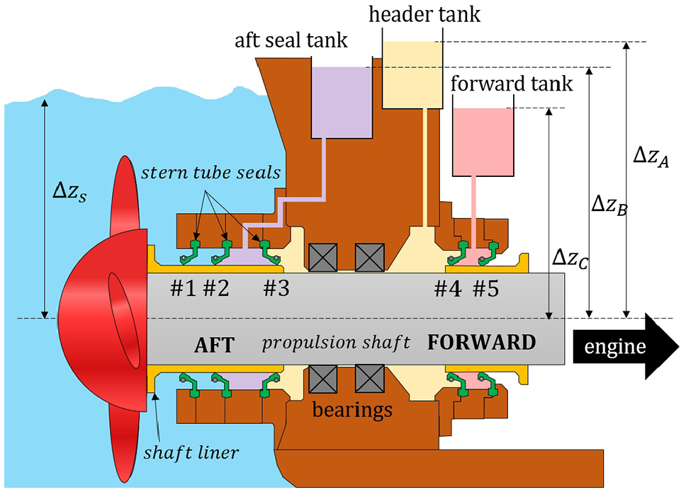
Usual disposition of the stern tube seals and the oil tanks in a ship.
Until the 1950s engineers thought that lubricated rotary seals operated in a similar fashion to dry rotary lip seals, by compressing the elastomeric lip of the seal against the rotating shaft to ensure a tight contact. It was not until Jagger 1 that the lubrication regime of rotary lip seals was taken into consideration. Jagger realized that the friction force of a lip seal was not proportional to its loading, as would be expected from a Coulomb-like frictional behavior. Additionally, some friction force was present even when the loading of the seal was almost null. Jagger stated that a continuous lubricant layer may separate the seal and the shaft, preventing direct asperity contact. Since then, researchers have tried to analyze the mechanisms promoting the separation between surfaces and, if the contact is not tight, why the lubricant does not leak through the seal.
Rotary lip seals are one of the most frequently used sealing components; 2 however, some mysteries still remain with respect to their working mechanism. The presence of hydrodynamics is repeatedly evidenced in rotary lip seal literature. Stakenborg 3 observed the cavitation of the lubricant through a sapphire glass shaft. The location of the bubbles shifted with the shaft angular velocity. Johnston 4 observed that, contrary to what it is expected from an Archard-like wear rate, rotary lip seals presented almost no wear after an initial running-in period. Kawahara et al., 5 Horve, 6 studied reverse pumping (also referred as upstream or back pumping). Reverse pumping is an inherent ability of rotary lip seals to pump liquid from the back side to the spring side of the seal, as shown in Figure 2. It is clear that reverse pumping could not develop in a tight seal-shaft interface. In contrast to journal bearings or thrust bearings, rotary lip seals do not present a convergent gap profile in the direction of rotation, hence there is no apparent source for hydrodynamic action. Nevertheless, in a similar fashion as journal or thrust bearings, rotary lip seals fail when the viscosity of the lubricant decreases excessively. 7

Inwards pumping ability of rotary lip seals (left) for normal: (a) and converse (b) installation. Syringe pumping test under converse installation (right). 8
Horve 9 noticed that seals with more micro-asperities on its surface showed better sealing characteristics, while excessively smooth seals showed a more erratic behavior leading to leakage. Up to now, the behavior of rotary lip seals has been explained by the presence of hydrodynamics at a microscopic level. 10 The micro-hydrodynamic pressure build-up between the surface asperities of the shaft and the seal leads to a load-carrying capacity which partially (or fully) replaces the seal-shaft radial load supported by direct asperity contact. The same micro-hydrodynamics can explain the reverse pumping mechanism. The shearing load resulting from the rotation of the shaft shifts the tip of the seal, distorting the asperities on its surface. Since the radial pressure profile between the shaft and the seal is not uniform, neither is the tangential force in the circumferential direction nor the consequent distortion of the asperities. Consequently, the asperities on the seal surface become aligned, forming ridges resembling a viscous seal or a herring-bone bearing. The location of the maximum radial pressure determines the equator of the sealing contact, that is, where the circumferential shearing force is the greatest. At that location, the two opposing microscopic screw pumps meet each other. Typically, in rotary lip seals it is ensured that the maximum contact pressure is located close to the spring side, thereby forcing a lubricant flow toward the spring edge. Alternative hypotheses for the film formation and sealing mechanisms are also found in the literature,10,11 but the hypothesis based on the micro-hydrodynamics generating a micro-pump is the only one that can explain the presence of hydrodynamics, the pressure profile-dependent reverse pumping mechanism, and the significant role of the surface roughness to the successful sealing of rotary lip seals. 10 It is thought that not a single unique lubrication mechanism but a combination of lubrication mechanisms is present in rotary lip seals. 12
Although the micro-hydrodynamic hypothesis described above may explain the operation of rotary lip seals, it is still not clear whether the separation of the seal and the shaft is partial or total. Micro-hydrodynamics may develop on the full film, mixed, or boundary lubrication regimes13,14 (see Figure 3). Furthermore, as for any hydrodynamic component, it is likely that some designs lead to a complete lift-off while other designs do not. The parameters defining the boundary between the mixed and the full film lubrication regimes in rotary lip seals are yet to be determined. It is clear that leakage-free full film lubrication is convenient as the wear rate becomes virtually zero.
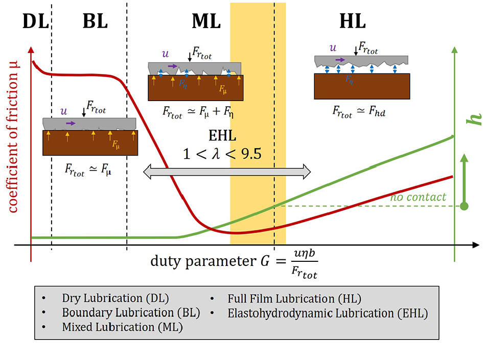
Stribeck curve.
The separation between the seal and the shaft, fluid film thickness or gap has been the subject of extensive research as it provides a definitive answer to the lubrication regime in which rotary lip seals operate. 15 A wide range of techniques were implemented, including electrical resistance, 12 capacitance with a conductive rubber compound, 16 laser induced fluorescence (LIF), 17 and magnetic resistance, 18 leading to film thickness values between 0.1 and 5 µm. Recently, Wennehorst and Poll 19 presented remarkable film thickness measurements using the LIF technique under a wide range of operating conditions.
The lubrication regime is often inferred by comparing the film thickness with the composite standard deviation of undeformed surface heights of the two surfaces
Ogata et al.
12
determined the boundaries of the lubrication regimes in the Stribeck curve by measuring the film thickness of several rotary lip seals under a wide range of operating conditions. The values for the dimensionless duty parameter
Boundaries of the lubrication regimes determined by Ogata et al. 12

Johnston and Vogt 20 tested a comprehensive amount of rotary lip seals showing that, while some seals follow the traditional Stribeck curve, other seals did not exhibit the typical boundary lubrication regime. Johnston concluded that the behavior of rotary lip seals cannot be captured solely by the traditional Stribeck curve, hence additional variables such as the surface roughness or the seal material characteristics must be included. 15
The lubrication regime of rotary lip seals can also be deduced from fitting computational models to indirect measurements. Typically, the film thickness value is selected so the model shows good agreement with the frictional torque measurements. These models require specific data that must be obtained beforehand, typically the contact width, the characteristics of the seal and shaft surfaces, and radial load between the seal and the shaft. Specialized equipment is required for this. 21
Setups for testing rotary lip seals under dynamic conditions are presented in the literature.3,22 Almost all the research on rotary lip seals focuses on seals where the lubricant is placed at the spring side, while the back side is filled with air as shown in Figure 2. These setups usually allow the seal to be instaled conversely so as to measure the potential of the reverse pumping. The reverse pumping can be measured by the syringe test (Figure 2) or by measuring the oil flow rate when installed conversely, as shown in Figure 4. 23 The metered tube method has the inconvenience of continuously varying the hydrostatic pressure conditions of the seal. Burkhart et al. 24 recently measured the oil migration across the seal by monitoring precisely the hydrostatic pressure variation resulting from the oil level rise. Note that when the seal fails due to causes such as overheating, excessive wear or misalignment, the leakage develops in the other direction: from the spring side toward the back side. As in many applications, the oil level on the spring side is often set to half the shaft. The torque is typically measured via in-line torque sensors 25 or by measuring the reaction on the seal housing.5,26 Lubricated rotary lip setups generally arise from an auxiliary seal preventing the leakage of the oil in the chamber next to the driving shaft. Additionally, as in a concentric cylinder rheometer, the viscous shearing of the lubricant hampers the rotation of the shaft. The contribution of both the auxiliary sealing components and the lubricant shear must be subtracted from the torque readings. The temperature at the seal-shaft interface is usually deduced by placing a thermocouple near the seal-shaft contact zone. Thermocouples can be placed at the spring groove, 16 within the seal, 26 or inside the rotating shaft. 27 Infrared cameras have also been used.25,28 Finite Element (FE) models are often used to predict the temperature difference between the measurement point and the actual contact.

Sketch of the test apparatus used by Kawahara et al. 5 for measuring the reverse pumping of a rotary lip seal in 1980s.
The time required to reach stationary conditions increases with the seal diameter. 26 Furthermore, some setups are designed without a temperature control-loop of the bulk oil, 25 hence the steady-state temperature of the liquid at each side of the seal depends on the operating conditions. Due to the poor thermal conductivity of elastomers, the overall seal temperature is determined to a large extent by the bulk oil temperature, so this must be taken into account in terms of the elastomer properties and the thermal expansion. Additionally, extensive research on the shaft and seal surface characteristics have been conducted as they have been shown to impact the migration of the lubricant across the seal.28–30 Cylindrical grinding of the shaft, for example, can lead to a micron-scale screw thread on the shaft pumping oil from one side of the seal to the other. Plunge grinding is shown to minimize the shaft lead and, consequently, the liquid pump rates. 31 Studies on pressurized rotary lip seals are scarce. Jagger 1 studied at what maximum pressure difference a rotary seal could operate without leaking, given a specific shaft velocity and loading of the contact.
The simplest model used to describe the operation of rotary lip seals assumes a laminar flow between concentric rotating cylinders.
9
The frictional torque
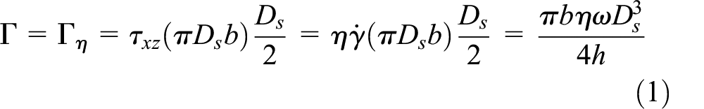
Jagger 1 noticed that the frictional torque-shaft velocity curve shows a positive ordinate intercept. That suggests that direct asperity contact occurs, at least at low velocities, hence equation (1) is often generalized by including a dry friction term as in equation (2).16,22

Consequently, the dry friction coefficient

The contact temperature increase with respect to the sump oil temperature is often predicted from the heat dissipated density

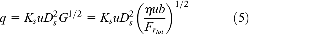
Kawahara et al.
5
noticed that the flow rate across the seal when installed conversely, that is, flooded seal back side, can be related to the duty parameter
The first deterministic models for rotary lip seals were developed in the 1990s by Gabelli, 34 Gabelli and Pol, 35 and Salant and and Flaherty. 36 The hydrodynamic pressure generated on the microscopic level is modeled by solving the Reynolds partial differential equation on an equivalent gap profile representing the separation between the seal and the shaft. During the next decades a wide range of models of various complexities were developed. The distortion of the shaft asperities, 37 the impact of operating with a non-Newtonian lubricant, 38 the direct asperity contact, 39 the viscoelasticity of the seal, 40 or the presence of a meniscus 41 were added to these deterministic models.
Stern tube seals, together with the seals used for wind and water turbines, constitute one of the largest types of rotary lip seals.
2
The same type of seal is installed in both the aft and forward sealing packages as shown in Figure 1. Fluoroelastomer compounds are the preferred choice for the stern tube seals due to their inertness. The linear velocity of the shaft depends on the turning speed and the diameter of the shaft liner (
Average pressure difference across each seal shown in Figure 1 under loaded and unloaded conditions.
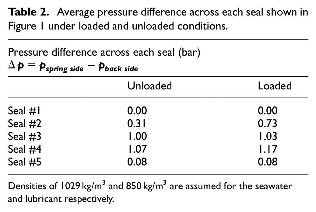
Densities of 1029 kg/m3 and 850 kg/m3 are assumed for the seawater and lubricant respectively.
The innermost seal, seal #5 in Figure 1, is the only ring sealing against an oil-air interface. The rest of the seals are fully flooded with liquid on both sides. In practice, the outermost seal facing the seawater, seal #1 in Figure 1, suffers wear quickly. An oil-water mixture is expected between seal #1 and seal #2. It is common practice to fill that space with grease. In fact, seal #1 acts as a dirt excluder, preventing the entrance of larger particles and marine life into the stern tube. 29 Seal #1 does not hold any pressure. Both an air-oil interface and a water-oil interface, that is, two menisci, are found in the stern tube. Since the back side of stern tube seals is flooded with liquid it is anticipated that, if stern tube seals behave as common rotary lip seals (see Figure 2), they constantly leak lubricant to the environment, leading to a lower friction coefficient.1,8 The rheology of the lubricant of the stern tube plays an important role in the system. In Borras et al. 42 a strong temperature-dependence and occasional shear thinning were observed for stern tube lubricants. Additionally, the large dimension of the stern tube hardware challenges the dimensional accuracy, hence the nominal parallelism between the shaft and the seal. 43 The loading of the propeller, for example, may also lead to the misalignment of the shaft. Further, due to the dimensions, the surface finish becomes expensive and the lead 31 on the shaft liner surface is generally overlooked.
Cargo vessels and tankers, among others, travel around the world 365 days a year. The service time of these vessels has to be carefully planned so the most profitable sailing time is achieved. Every 2–5 years such vessels are sent into dry dock for maintenance so the hull can be repaired and all the critical components replaced even if they are not significantly worn, for example, the stern tube seals. Consequently, the stern tube seals must guarantee the reliable sealing of the stern tube until the next service of the ship. A failure of the sealing system of the stern tube generally leads to a costly unscheduled visit to the dry dock. When the seals are serviced after a few years of operation, the condition of the seals differ from each other. Seal #2, for example, is usually heavily worn while seal #5 looks as good as new. In fact, not only the shaft speed but also the pressure difference, the contact temperature, the lubricants, and probably the shaft-seal alignment are specific to each seal position. This suggests that each seal may operate under a different lubrication regime.
The spillage of lubricant to the ocean is of great concern with respect to the marine environment; the use of mineral lubricants has therefore been limited in some countries. 42 Etkin 44 showed that the stern tubes of barge carriers, tankers, and navy ships “consume” (i.e. spill) between 10 and 20 L/day. In fact, lip seals are known to not reliably separate two liquids. 45 The back-to-back strategy with a vented chamber instead shows improving results, keeping the two liquids apart. This is already implemented in the propulsion system of some ships. Alternatively, few newbuild ships use seawater to lubricate the stern tube bearings.
The present work focuses on the operation of a particular stern tube seal of 200 mm nominal diameter. Combining both experimentation and modeling analyses, the behavior of this large rotary lip seal is studied. A specialized setup was developed to measure the frictional torque, contact temperature, and the under-lip flow rate under a wide range of velocities and pressure differences. The suitability of the already-available formulae for rotary lip seals is reviewed for the stern tube seal application. This study aims to create a solid foundation from which to tackle the large spillage of lubricant to the environment while extending its service time.
Materials and methods
The test rig sketched in Figure 5 was developed to measure the frictional torque, the flow rate, and the operating temperature of a stern tube seal under various shaft velocities and pressure conditions. The pressure at each side of the seal is indirectly set by adjusting the pressure of the air space at the top of each tank according to the readings of the pressure gauges (Hydac, Germany). The system was designed to bear pressures of up to 2.5 bar. The 30 kW three-phase motor (Elsto Drives & Control, The Netherlands) allows the angular velocity of the shaft to be varied, reaching a maximum linear velocity of 10 m/s for a 200-mm shaft liner. The temperature of the sump oil in each side of the seal is independently controlled by circulating the liquid through two heat exchangers, as shown in the same Figure 5. Approximately 80 L of lubricant are required to run the setup. All the tests were conducted using a mineral oil-based lubricant exhibiting a kinematic viscosity of 133 and 14 mm2/s at 40°C and 100°C respectively. Further details on the rheology of the lubricant are presented in Borras et al. 42
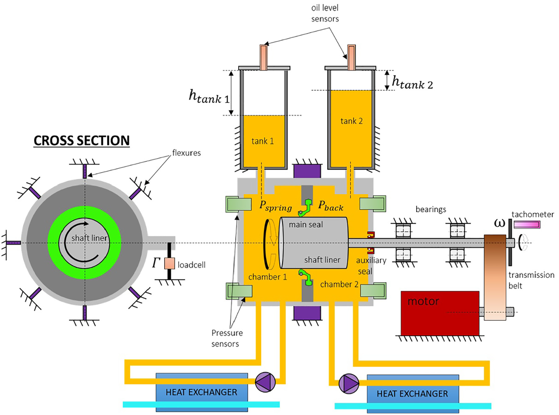
Setup for measuring torque, seal temperature, and flow rate of a stern tube seal under dynamic conditions.
The measurement of the frictional torque is deduced from its reaction in the seal housing, that is, the drum. The drum is suspended by several flexures carrying the weight of the drum while slightly constraining the rotation of the testing chamber. The rotation of the drum is prevented by a single lever connecting it to the ground. The lever has a high accuracy S-beam load cell of 50 lb (Futek, USA), as shown in Figure 5, from which the frictional torque is deduced. The contribution of both the lubricant and the auxiliary seal to the frictional torque are also measured by the load cell. However, the contribution of the auxiliary seal and the lubricant is low as it operates against a smaller shaft diameter and the space between the shaft and the drum is large, respectively. The residual torque, that is, of the auxiliary seal and the lubricant, was mapped at various velocities and pressures by operating without the main seal and later subtracted from the measurements with the main seal assembled. For clarity, the main seal is mounted so the low pressure side, that is, the back side, faces the chamber where the auxiliary seal seats (chamber 2 in Figure 5). This allows keeping the pressure constant on the back side so the auxiliary seal torque is dependent only on the shaft velocity.
The flow rate across the seal is obtained by measuring the oil height level in each tank using two distance sensors. Monitoring the oil height variation at both sides of the seal ensures that the oil volume migrating from one tank ends in the other one and does not leave the system, in other words it does not leak. Therefore, only measurements giving the same slope on both oil level sensors in time were accepted to ensure the mass of the oil is conserved. Notice that by increasing or decreasing the height of the lubricant the hydrostatic pressure on each side varies, affecting the operating conditions of the test. 24 To prevent that, a control loop is set at each side of the seal, adjusting the pressure of the air space above the tanks. This way, when the oil height increases the air pressure on the tank is decreased so the pressure on that side matches that prescribed for the test. Note that although this does not occur in the stern tube system of a ship, the section of the tanks on a ship is significantly larger, resulting in a minimal hydrostatic pressure variation with leakage. Air pockets formed occasionally while operating the setup. It is thought that the origin of the air bubbles in the system is a combination of gaseous cavitation, the reverse pumping of the auxiliary seal, and the pumps used for controlling the oil sump temperature. The presence of an air bubble within the system drastically impacted the measurement of the oil level. It was shown imperative to provide an escape route for the air bubbles to the top of the tanks. Interestingly, breathers are present in the oil system on a stern tube of a ship. 29 Additionally, as described in Engelke, 27 the thermal expansion of the lubricant was shown to impact the results strongly and the density-temperature relationship presented in Borras et al. 42 was used. The surface finish of the shaft was grinded to the right outer diameter. No plunge ground surface operation was carried out. The final lead of the shaft was tested according to 46 showing no significant directionality.
The temperature of the stern tube system was monitored by a set of thermocouples distributed at various parts of the setup. The temperature of the oil at each side of the seal strongly determines the temperature of the seal and the housing parts. To account for the temperature at the contact, while avoiding having to drill a hole to the seal, 26 a thermocouple was clamped between the garter spring coils providing the temperature on the spring groove as in Organisciak et al. 16 The temperature at the contact was approximated by using the Finite Element (FE) model presented in Borras et al. 21 Figure 6 shows the relationship between the temperature at the groove and the temperature at the contact. The lubricant viscosity was calculated from the contact temperature according to. 42

The temperature at the contact is obtained from the FE model presented in Borras et al. 21 Thermocouple measurements were placed close to the contact for validation.
A 200-mm seal was tested under three shaft velocities and four pressure differences leading to twelve different operational points. This study focuses on the steady state operation of the stern tube seal, that is, once it has undergone the initial running-in period. It is considered that the steady-state regime is reached once both the temperature and friction torque readings stabilize, showing a variation of less than 5% for at least 1 h. The sump oil temperature at both sides of the seal was set to 20°C. The tests were repeated three times for each operational point and the average values are presented.
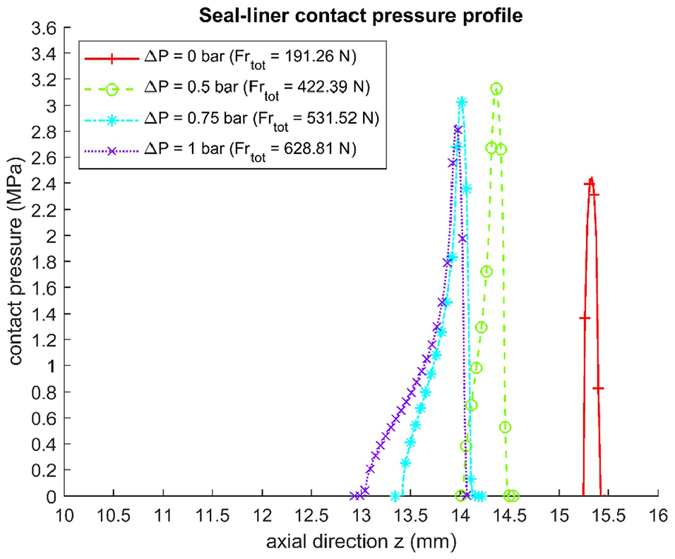
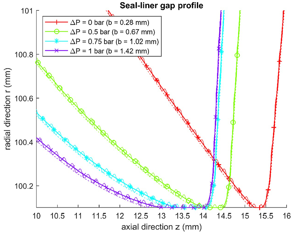
The accuracy of the analytical expressions, equations (1), (2), and (4), for the stern tube seals application was reviewed. The authors previously presented the static characterization and modeling of the stern tube seal type tested in this manuscript. 21 Further details on the seal geometry and the model characteristics can be found there. The seal-shaft contact pressure and the deformed seal profiles are reproduced for commodity in Figures 7 and 8, respectively. The results showed a minimum accuracy of 4% and 8% for the radial load and the contact width respectively. The surface roughness analysis of both the seal and the shaft and seal material characterization are also disclosed in the same publication. The surface roughness in the direction of rotation is 0.85 and 0.14 µm for the seal and the shaft liner respectively.
Results
A particular stern tube seal of 200 mm nominal diameter was tested under the operating conditions as listed in Table 3, that is, four pressure differences and three shaft velocities. Figures 9 to 12 show the frictional torque, the contact temperature, the flow rate, and the heat dissipation of the seal respectively.
Seal operation conditions tested with the dynamic setup.

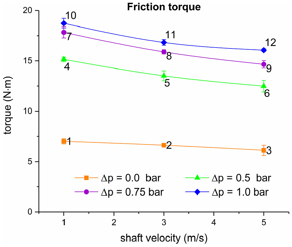
Frictional torque measurements after subtracting the parasitic friction.

Contact temperature predicted from the garter spring temperature measurements via the FE model presented in Borras et al. 21

Flow rate measurements from spring side to back side of the seal. The flow rate

Heat dissipated at the contact
The torque decrease with an increase of velocity shown in Figure 9 is not often observed in rotary lip seals.
19
El Gadari et al.
47
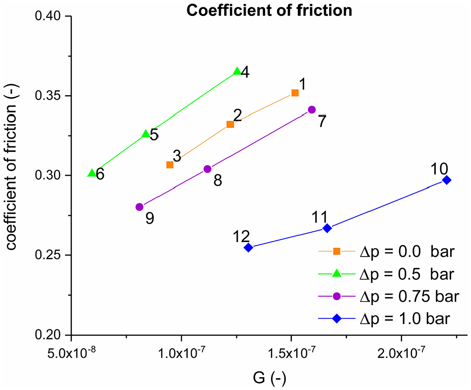
showed a friction-velocity curve presenting a maximum friction at 2500 rpm; beyond that velocity the torque decreased. That is explained by a larger viscosity decrease than the velocity increase. The same occurs with the stern tube seal tested and it is clearly evidenced when plotting the coefficient of friction
Stribeck curve deduced from the friction and temperature measurements.
Figure 13 suggests that the operational points tested belong to the transition between mixed and the full film lubrication regimes, that is, at the right side of the minimum friction coefficient value of the Stribeck curve. Figure 3 shows that EHL encompasses the minimum of the Stribeck curve, hence the slope of the
Also, previous studies showed a linear correlation between the friction coefficient and the cubic root of the duty parameter

Coefficient of friction as a function of G1/3 as shown in Hirano and Ishiwata. 33
The temperature at the contact is shown to be proportional to the heat dissipation density

Temperature increase at the contact. The oil bath temperature is kept at 20°C for all the tests.
The validity of equation (5) to relate the operating conditions of a rotary lip seal to the flow rate across its contact was analyzed. Figure 16 shows that Kawahara’s et al. 5 expression is applicable to the stern tube seal tested, exhibiting R2 above 0.93.

The flow rate across the seal measured in the experiments matches well with the correlation used by Kawahara et al. 5
The film thickness at the contact was not measured. However, an approximated value of the seal-liner separation can be indirectly obtained by fitting equation (2) to the frictional torque measurements, as shown in in Figure 17. As expected, a larger film thickness results from assigning a lower viscous shear load (
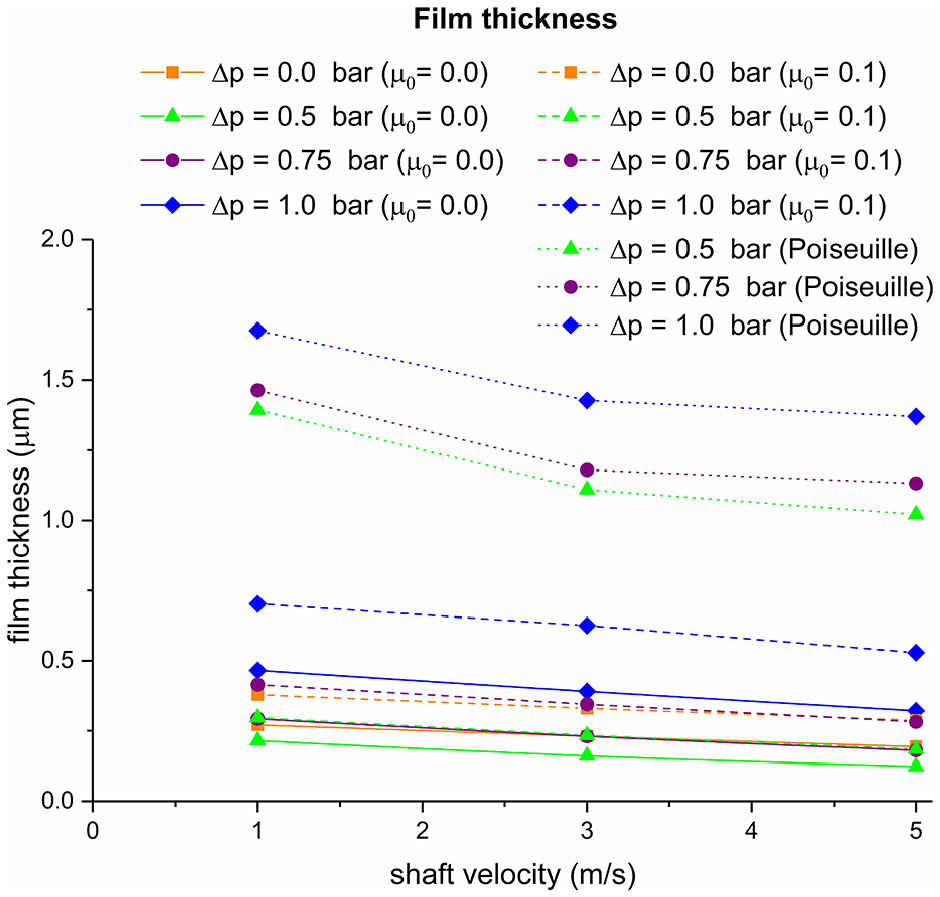
Film thickness prediction deduced from the frictional torque and flow rate measurements.
Alternatively, given that the liquid migration observed follows the natural flow direction, the gap required assuming a fully pressure-driven flow can be estimated, leading to reasonable results (see Figure 17). Note that some lubricant is driven across the seal even when there is no pressure difference, hence Poiseuille’s expression alone cannot explain it. The film thicknesses shown in Figure 17 follow the central film thickness expression for soft-EHL
Discussion
The frictional torque measurements revealed that the stern tube seal analyzed operates at the right side of the minimum of the Stribeck curve. Notice that the separation between the seal and the shaft decreases as the velocity increases. That is inconvenient as it is a self-induced mechanism: the greater the shaft velocity, the higher the contact temperature, further decreasing the film thickness, and leading to an even higher temperature. The film thickness predictions allow the lambda ratio to be estimated at each operation point. The lambda ratio ranges from 0.1 to 2 for all the estimated film thicknesses shown in Figure 17 (
Reverse pumping typically ensures the flow of lubricant from the back side to the spring side even when pressurized, 29 that is, upstream pumping. The results show a flow rate from the spring side to the back side instead. This occurs even when there is no pressure difference. No lubricant migration was observed when the shaft was not rotating. The contact pressure profile between the seal and the shaft is almost symmetric when there is no pressure difference and becomes more skewed when the pressure difference increases. 21 Therefore, when the seal is not pressurized neither the reverse pumping nor the pressure-driven flow take place. The shaft liner was manufactured following the same procedure used for the real application, hence a screw thread may be left. The lead of the shaft can explain the oil migration when non-pressurized. Alternatively, the loss of the nominal parallelism between the seal and the shaft 43 or the poor followability of the seal at larger velocities 40 are also plausible explanations. Reverse pumping is expected to be present under pressurized situations, that is, counteracting the natural flow direction. However, besides a skewed radial pressure profile, the surface roughness or the stiffness of the seal are also of importance for the generation of the upstream pumping phenomenon.
The fluid film thickness was deduced from the frictional torque and from the flow rate measurements, leading to results between 0.1 and 2 µm. The friction torque in equation (2) is represented by two terms: one for the direct contact between asperities and the other one for the viscous shear of the lubricant. Notice that the dry friction force term in Engelke
27
remains constant when the shaft velocity increases. A larger hydrodynamic pressure build-up usually results from an increase of velocity, leading to a decrease of the load carried by the direct asperity contact. Equation (2) assumes that hydrodynamics does not play a role as in concentric rotating cylinders. A more accurate approximation of the film thickness may be obtained by setting a non-constant
Equation (4) was shown to accurately capture the temperature at the contact. The formula relies on the
The models for rotary lip seals found in literature are generally for smaller rotary lip seals with a null pressure difference. The details on the stern tube seals operation are kept within the original equipment manufacturers, so they have not been disclosed. The results presented constitute a first reference to large rotary seals under pressurized conditions. The shear thinning observed in some of the stern tube lubricants 42 would lead to a further decrease in the film thickness at higher velocities. This would reduce the service time of the seals. The results obtained show a migration of lubricant from the spring side to the back side. In that case, seawater would leak to the stern tube increasing the liquid height of the oil tanks. The lubricant spillage in real ships is estimated to be a hundred times larger and in the opposite direction. 44 Although seals operating with a water-oil interface were not tested, the latter suggests that there is an additional oil spillage mechanism in ships which was not captured by the stern tube test setup developed. The transient operation, a large seal-shaft misalignment, or sudden events such as the propeller being temporarily out of the water, can explain the large oil consumption values reported. Additionally, differences in the flow rate of each seal results in a different pressure condition from the original one. Monitoring the oil level of the tanks while sailing would contribute to the understanding of the complex stern tube system.
Every rotary lip seal has its own characteristics and what applies to one type of seal does not apply to others. The models presented require the dry friction coefficient or the equivalent film thickness, among other things, to be determined experimentally. When the material of the seal is switched, for example, the radial force, the contact temperature, and the seal followability vary, leading to a completely different scenario.
Conclusion
A testing setup was developed, allowing an insight into the actual operation conditions of stern tube seals. The rig made it possible to accurately measure the frictional torque, flow rate, and operating temperature under a wide range of velocities, oil sump temperatures, and pressure differences. On one hand, the friction torque results revealed that the behavior of a stern tube seal resembles the operation of smaller rotary lip seals with nominal diameters up to 60 mm. It is noteworthy that the frictional torque decreased when the shaft velocity increased, leading to narrower film heights. On the other hand, the direction of the flow rate across the seal calls into question whether a reverse pumping mechanism is necessary at all. The existing expressions relating the operational conditions of rotary lip seal are shown to hold for large pressurized rotary lip seals as long as the results at each pressure difference are characterized individually.
Footnotes
Appendix
Nomenclature

| Contact width | ||
| Fluid film thickness | ||
| Shaft diameter | ||
| Dynamic viscosity of the lubricant | ||
| Overall coefficient of friction (COF) | ||
| Dry friction coefficient resulting from asperity contact | ||
| Frictional torque | ||
| Lubricant frictional torque (viscous term) | ||
| Asperity contact frictional torque (dry term) | ||
| Duty parameter | ||
| Shaft liner angular velocity | ||
| Shaft liner linear velocity | ||
| Pressure difference | ||
| Viscous shear | ||
| Lambda ratio | ||
| Shear rate | ||
| Total radial seal force | ||
| Combined root mean square roughness | ||
| Root mean square roughness | ||
| Roughness maximum peak height | ||
| Hydrostatic height | ||
| Gravity constant | ||
| Density | ||
| Flow rate from the spring side to the back side | ||
| Normalized flow rate | ||
| Temperature of the oil sump | ||
| Temperature at the seal-shaft contact | ||
| Proportionality factor for predicting the contact temperature | ||
| Suction parameter | ||
| Characteristic sealing proportionality parameter | ||
| Heat dissipated density | ||
| Friction heating, power dissipation |
Handling Editor: James Baldwin
Declaration of conflicting interests
The author(s) declared no potential conflicts of interest with respect to the research, authorship, and/or publication of this article.
Funding
The author(s) received no financial support for the research, authorship, and/or publication of this article.