
Abstract
To predict and minimize machining distortion in the manufacturing process, bulk residual stresses in aeronautical components with distinct geometries were investigated via experimental mechanics and numerical simulation. The residual stress state was appropriately simplified according to geometric/processing feathers and deformation patterns of the investigated parts. In each case study, an optimal experimental method was selected to reconstruct the concerned stress tensor. Thereafter, qualitative comparison and validation were performed using cross-method verification and/or numerical simulation. Additionally, the spatial resolution and distribution characteristics of the residual stress were analyzed and discussed in detail. The results revealed that thermal and mechanical nonuniformity caused by material processing is the main source of bulk residual stress in the investigated components. Furthermore, the effectiveness of the contour method on the measurement of different geometric components was verified by numerical simulation. Combining the accurate measurement of the characteristic plane and the appropriate numerical simulation of the global stress field, an engineering-oriented approach for full-field stress evaluation was proposed. This research can provide valuable engineering guidance and suggestions for stress evaluation and distortion analysis prior to manufacturing of integral structures.
Keywords
Introduction
Lightweight design for modern aircraft has led to the extensive application of integrally stiffened structures. 1 Compared with traditional riveted joints, monolithic parts demonstrate a good combination of functional shape and stiffness–weight ratio; however, integral structures are typically milled from thick plates or large forgings, inevitably resulting in a high ratio of material removal and bulk stress relaxation. An increasing removal rate during the machining process decreases the stiffness incrementally and significantly increases the machining distortion. It has been reported that bulk residual stress is one of the primary factors causing shape deflection in the manufacturing of aeronautical components. 2 Residual stress also has a profound effect on structural safety and service performance, such as by causing fracturing, stress corrosion cracking, and fatigue 3 ; therefore, accurate assessment of the bulk residual stresses is essential for manufacturing aeronautical structures.
Residual stress cannot be measured directly; only displacement, strain, or lattice spacing can be measured and then converted to stress.3–5 Moreover, a stress field has a natural self-equilibrium, which varies with geometry and evolves with material processing cycles. For a given component with specific conditions, a reasonable assumption of the stress state and the appropriate selection of measurement techniques are always the key issues for engineering analysis.
For aeronautical plates, a plane stress state is often assumed in prestretched aluminum sheets due to their dimensional features and approximately uniform distribution of residual stresses. The slitting results for 45 mm, 6 50 mm, 7 and 76 mm 8 7050-T7451 plates showed high accuracy and excellent spatial resolution for the measurement of the low stress range (±20 MPa). Additionally, the layer removal method (LRM) was adopted to measure the residual stress in 30 mm, 9 40 mm, 10 and 50 mm 11 aluminum plates using a displacement-based algorithm instead of a conventional strain gauge. Compared with the slitting results, the modified LRM results demonstrated a basic trend with fluctuations due to low spatial resolution. Nonuniform residual stress is typically generated when severe processing, such as welding and peening, is applied. In such cases, a high gradient can be accurately determined using the slitting or contour method (CM). The slitting results for a one-dimensional (1D) curve clearly showed stress concentration at the heat-affected zone in butt-welded 12 and electron-beam-welded 13 plates. A more detailed two-dimensional (2D) stress map was reported using the CM, which was validated using welded13–17 and laser-peened thin plates.18,19 It should be noted that CM measurement is highly uncertain for detecting stress in the near-edge region of thin samples. Accurately measuring deformed cut-planes, appropriately selecting fitting functions, carefully processing the data, and performing additional verification are usually recommended for CM tests of thin plates. 20
For aircraft keel beams, cross-sectional axial residual stresses have received more attention, since deflection often occurs and varies with a long axis. Distortion analysis requires adequate stress data for distinct cross-sectional planes, which makes the CM ideal for measurement. 21 In particularly, an irregular beam with variable cross-sections renders measurement difficult for other common techniques, but the CM still demonstrates high spatial resolution for 2D stress maps of an arbitrary slice along the axis. 22 Additionally, slitting can be applied to measure bulk stress in a simple-geometry beam with multiple cutting slices, but 2D stress maps need postprocessing to align the 1D curves. 23 Furthermore, neutron diffraction (ND) allows nondestructive determination; thus, it can be used to validate CM results at the same measurement position. 21 Depending on different engineering materials, neutrons have limited penetration depth for detection. 24 Perhaps biggest limitation is that the neutron source is expensive and relatively difficult to obtain for common engineering purposes.
For bearing components, roundness is the most important parameter affecting quality; thus, the associated hoop residual stress is often a concern. X-ray diffraction (XRD) can detect near-surface residual stress nondestructively and then provide a reference for turning processing. 25 Detailed cross-sectional residual stresses can be determined nondestructively via ND; detected data have revealed the nonuniform evolution of stress fields during a turning sequence. 26 In addition to weld-joint pipes, heat-affected zones with a high stress concentration strongly affect structural integrity and safety. Weldments typically combine deep hole drilling with XRD and numerical analyses to obtain the required stress data. 27 Moreover, a hoop stress map was determined using the CM and validated by ND in an electron-beam-welded uranium cylinder. 28 Recently, a novel method was proposed using superposition theory to allow the CM to determine the original state of residual stress combined with the other surface measurement.29–31 It should be noted that a cylinder/ring has an equilibrium moment across section, which may result in error during contour and slitting measurement. 20 To avoid the released-moment effect, a two-step-cut and compensation calculation was invented to assess the original residual stress state. 32
It is relatively difficult to evaluate stress fields in large forgings due to a three-dimensional (3D) stress state and multiple processing cycles; for example, solution treatment, quenching, artificial aging, and cold work result in complex stress superposition in aviation aluminum productions.2,33,34 The standard hole drilling method is only suitable for examining critical regions in load-bearing components due to its adaptability for point measurement. 35 Based on three independent cuts, the CM demonstrated good spatial distribution on each measured plane in an aluminum hand forging test, 36 but these results need further verification. ND produced area maps for each stress tensor, which clearly showed a transition from a uniform quenched state to a complex cold-compressed state in AA7449 forging blocks 2 ; however, the detection process is time consuming and costly. Internal stress states can also be detected using high-energy synchrotron diffraction, but with a lower penetration depth than ND. 37 Additionally, the finite element method (FEM) is an effective approach for efficiently evaluating stress fields in engineered structures. Coupled thermo-mechanical analysis can be employed to predict stress fields in cold-worked components, such as stretched, 33 compressed, 38 and rolled ones. 34 Note that FEM prediction is a trial-and-error process, and its accuracy relies heavily on accurate parameters, such as material properties and interaction conditions. It has been suggested that FEM simulation should follow experimental validation. 39
A significant number of investigations have been conducted and reviewed40–44 on the merits of measurement techniques for various components, but appropriate evaluation of components with specific geometries and processing histories still requires engineering judgment and experience; therefore, the present investigation examined various aeronautical engineering case studies. A range of component types was used to provide sound suggestions and guidance for stress evaluation. The bulk residual stresses within plate, beam, cylinder, and block specimens were investigated using experimental mechanics. A brief qualitative comparison and validation were then conducted to insure accurate modeling. The results for each case study were used to highlight the capabilities of the employed technique. Finally, a hybrid method for engineering stress estimation was proposed.
Specimen geometries and assumption of stress states
As Figure 1 shows, residual stress measurements were performed on four types of components (i.e. plate, beam, cylinder, and block) with distinct geometries. The residual stress state in each case was assumed according to the geometric features of the test specimen. The measured stress tensor was determined based on the primary contribution to distortion.

Geometric feathers and primary concerned stress tensors in different components.
Specimen conditions and experimental procedures
Thin-deformed aluminum plate
Laser peening can cause higher-magnitude and deeper compressive stress in target components compared with mechanical shot peening. It has been used to form wing panels in new generation aircraft. 45 This study examined the biaxial state of residual stress in two laser-peened plates.
The plate specimens were 300 mm × 100 mm × 3 mm and were extracted from a 25.4 mm-thick prestretched aluminum 7055-T7751 plate (Alcoa Corporation, PA, US). A finish milling process was employed to achieve a smooth surface prior to peening. Minimum and maximum irradiation energies of 5 J (7.85 GW/cm2) and 7 J (10.99 GW/cm2) were adopted for laser peening of the entire surface, respectively. Black tape was used as an opaque overlay, and 1.5-mm laminar flow (water) was used as a transparent overlay.
Two laser-peened plates demonstrated substantial deformation (Figure 2), which posed challenges for residual stress measurement. A high stress gradient, a thin cross section, and a deformed shape require high spatial resolution and sensitivity, which make them ideal for the slitting method. To avoid deformed shapes and the stress relaxation effect, 20 mm × 10 mm samples were extracted in both a rolling (RD, x) and transverse direction (TD, y) to independently determine the stress tensors (σ x , σ y ) in each direction. A wire electrical discharge machine (EDM) was employed for cutting, using a 0.2 mm-diameter brass wire. Strain gauges with waterproof protection were attached to the backs of the test samples to measure the released strain. A 50 μm incremental cut with a total depth of 2.7 mm (90% depth) was made during the slitting process. Data processing and stress calculation carefully followed the experimental instructions. 43 Additionally, laboratory XRD and incremental electropolishing were employed for comparison and validation.

Laser-peened plates with 5 J and 7 J irradiation energies.
T-section beam
Two 5600 mm-long aluminum 7050 T-section keel beams were investigated. Figure 3 shows that the cross-sectional dimensions were 760 mm × 121 mm. These two beams were both solution treated at 477°C for 5 h, followed by immersion quenching with water at 20°C. Consequently, one beam exhibited a T74 temper, which indicated artificial aging (without stress relief). The other exhibited a T7452 temper, which indicated a cold-compression process, was applied to relieve thermal stress with 1–3% plastic deformation.
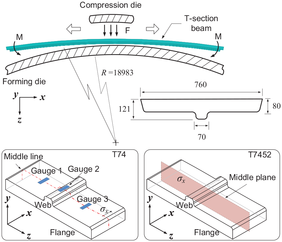
Schematic diagram of the aluminum 7050 T-section beam and two extracted samples with T74 and T7452 tempers, showing the measurement locations and stress tensors.
The first test was performed with a 7050-T74 beam. A full-scale measurement was relatively difficult to achieve due to the large dimensions; thus, a 300 mm-long specimen was extracted from the base material for testing. The LRM was selected for determining the axial stress component, σ x , due to its approximately uniform distribution in the T74 condition. The material removal was accomplished using a machining center with a 25 mm-diameter and a 3-toothed milling cutter. The program was set to “face milling” to remove each layer in 4 mm increments. During the processing, a coolant was used to prevent strain drift caused by milling-induced heat. The milling-induced residual stress was deemed to be negligible because it had only a minor effect on the deformation of the test specimen. Additionally, the milling processes were performed identically for each layer removal sequence to insure their identical effect on the strain measurement. A total of 16 layers and a cut depth of 64 mm were used for convenience, which were roughly half the maximum thickness of the web. As Figure 3 shows, gauges 1 and 3 were used to measure the through-thickness stress variation at two flanges, and gauge 2 was used to measure the center web. The released strain was recorded to calculate the stress distribution based on inverse solutions. 46
The second test on the T7452 cold-compressed beam was also performed on a 300 mm extracted sample. For this specimen, the axial stress σ x was determined using the CM due to the complex state of the T7452 temper. The specimen’s middle plane was cut using a wire EDM, with a 0.2 mm-diameter brass wire with an optimal machining parameter, to insure a good surface finish. The two cut planes were then measured using a non-contact laser sensor to record the deformation caused by the relaxation of bulk residual stress. Data processing and FEM calculations carefully followed the CM experimental instructions.44,47
Furthermore, a numerical approach was employed to verify both the LRM and the CM results for the T74 and T7452 samples, respectively. The detailed materials and interaction parameters for modeling were set according to the literature.22,33 A coupled thermo-mechanical model was adopted for the T74 sample, while thermal and mechanical state superpositions were considered for the T7452 sample.
Cylinder section
A cylinder section of 352 mm outside diameter and 280 mm inside diameter was cut from an aeroengine casing, which was made from Inconel 706 (Figure 4). This casing was subjected to a three-step heat treatment as follows: (1) solution treatment at 925°C for 1 h, and air cooled; (2) stabilizing treatment at 845°C for 3 h, and air cooled; and (3) precipitation treatment at 720°C for 8 h, followed by furnace cooling at a rate of 55°C/h at 620°C for 8 h. Unfortunately, substantial distortion occurred when the cylinder was split into two half-rings for subsequent processing; therefore, the circumferential residual stress, σ θ , was measured to investigate its contribution to roundness deviation.

Schematic diagram of the Inconel 706 cylinder and the extracted section for the CM measurement, showing the sample dimensions and the cut plane.
The CM was selected to determine a cross-sectional map of hoop residual stress, as shown in Figure 4. The experimental procedures included a wire EDM to cut a smoothly finished surface, a coordinate measuring machine (CMM) to record the deformations of the two cut planes, data processing, and a stress calculation using the elastic model.
Additionally, a FEM model was employed to predict the final state of the stress field. The thermo-mechanical parameters and processing conditions were set according to the material supplier’s report and the published literature. 48 Finally, the simulated stress field was compared with CM measurement to reconstruct the bulk residual stress.
The standard hole drilling method was also used to test the hoop stress around the inner circle at 30 ° intervals prior to sample extraction (Figure 4). A total of 12 measured points were acquired for comparing the FEM predictions. The hole drilling employed an RS-200 Vishay system (Vishay Precision Croup, PS, US) and carefully followed the ASTM E837 standard. 35
Forging block
Aluminum 2014-T6 is used on occasion for applications requiring high strength, high temperature, and hardness, such as aircraft heavy-duty frames and spacecraft parts. Unfortunately, the relaxation of bulk residual stress leads to severe dimensional deflection in the manufacturing of frame structures due to a high material removal rate; hence, a reliable 3D stress field is necessary for distortion prediction and analysis.
A 250 mm × 250 mm × 96 mm 2014-T6 forging block was investigated. It was solution treated at 495–505°C, water quenched at 70–80°C, and artificially aged at 160°C for 16–20 h.
Experimentally, biaxial residual stress on the two reference planes in the block were explored using the CM, as shown in Figure 5. A more detailed 3D stress map was obtained using a two-step thermal-displacement approach, which involved state superposition of the thermal and mechanical effects. The thermal stress (step 1) was simulated using a coupled temperature-displacement model. The result was then set as an initial stress condition for the subsequent mechanical forging process (step 2). Two rigid molds were employed for forging compression onto the block specimen at room temperature. Through a comparative analysis of spatial distribution on the reference planes, the bulk residual stress could be evaluated correctly.
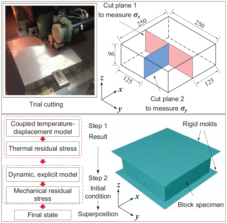
Aluminum 2014-T6 block forging, showing the dimensions, cut planes, and FEM model for the residual stress evaluation.
Results and discussion
Biaxial in-plane residual stress in the laser-peened plates
Figure 6(a) and (b) show the through-thickness distribution of residual stress after laser peening. The slitting results indicated that both deformed plates demonstrated approximately equal biaxial states. The compressive stress on the peened and unpeened sides were balanced by the tension in the center. It was evident that the peak value of the compressive stress increased with increasing irradiation energy, but the distribution pattern of the residual stress remained unchanged.

Through-thickness distribution of the residual stress using slitting and XRD: (a) a 5 J irradiated plate and (b) a 7 J irradiated plate.
The depth profiles for residual stress measured by the XRD are also shown for verification and comparison. The XRD results indicated that the near-surface area (0–0.5 mm) exhibited a high stress gradient due to laser peening. The compressive stress decreased instantly to zero at about 0.5 mm, which was consistent with the slitting result. The maximum difference between the two measured results was about 120 MPa, which could be attributed to a microstructure variation of grain refinement. 49 Except for the surface value, the slitting and XRD measurements demonstrated good agreement.
High-gradient residual stress within thin deformed plates is relatively difficult to assess by other common techniques, such as the LRM. The stress profile for a limited depth (1 mm) in laser-peened samples can also be characterized using the incremental hole drilling method (IHD). The experimental results50,51 indicated that the IHD may be suitable for the parametric study of cube samples without extensive deformation. Moreover, the stress curve of the IHD at the initial 100 μm exhibited a “hook” shape 51 and tensile stress, 50 possibly affected by drilling-induced plasticity. Additionally, the CM may not be suitable for measuring large-deflected plates because the thin sections make it challenging to conduct high-accuracy measurements close to the edges of peened surfaces.
In summary, the slitting method may be the most suitable technique for thin-peening-formed plates, since it can provide a through-thickness stress profile with high spatial resolution. The full-depth resolves were verified by cross-method data and satisfied equilibrium conditions.
Axial residual stress in the T-section keel beam
The LRM test on the T74 beam sample
Figure 7 shows the 2D area map of residual stress in the T-section sample using the FEM approach. Uniform distribution was evident, and high tension (320 MPa) in the section core was balanced by high compression (−430 MPa) near the surface. This pattern was mainly attributed to the temperature gradient and inconsistent shrinkage between the core and surface during the quenching process. 33 Similar uniform distributions of thermal stress were also observed in the quenched aluminum plate 34 and block, 2 although the T-shaped geometry was slightly different from the common rectangular section. The thermal gradient increased with increasing thickness, and in turn, the web center (Z = 380 mm) exhibited a higher stress magnitude than the flange due to its greater thickness.

2D area map of the residual stress in the T74 sample using the FEM approach.
As described in the introduction, approximately uniform distributed residual stress can be measured using the LMR. Figure 8(a) and (b) show the through-thickness variations of residual stress using an inverse solution based on raw and fitted-strain data. A typical thermal distribution was observed in the T-section. The center web clearly demonstrated higher tensile stress (around 300 MPa) than the flanges (around 200 MPa) due to a higher thermal gradient. The LRM measurements were also consistent with the FEM prediction.

Through-thickness profile of the residual stress using the LRM and FEM: (a) measurement at the two flanges and (b) measurement at the center web.
Large fluctuations were observed in the unfitted curve (raw strain), and smooth curves were obtained using the fitted strain. The reason for this deviation was largely attributed to cumulative errors, due to inversely calculating the stress, layer by the layer, using the equilibrium condition. The LRM calculation naturally relies on the released deformation (strain) caused by material removal.46,52 Unfortunately, the T-section exhibits good stiffness, which partly inhibits the deformation caused by residual stress relaxation; thus, a large amount of material (4 mm) had to be removed to obtain an adequate response, resulting in low spatial resolution. Moreover, the LRM results were the averaged values for a certain thickness, potentially leading to an underestimation of the magnitude at the measured locations (Figure 8).
In summary, the LMR demonstrated limited accuracy in the measurement of uniform residual stress in the T-section sample, but it is relatively straightforward and effective for prior estimation of machining distortion.
The CM test on the T7452 beam sample
Figure 9 shows the 2D area map of residual stress in the T7452 sample using the FEM approach. The T7452 state was a superposition of thermal (T74) and cold-work residual stress (T-52). A complex and nonuniform distribution of the residual stress was evident, since cold compression resulted in severe plastic evolution and substantial relief of thermal stress. The distribution pattern was still symmetrical with respect to the web center (z = 380 mm), and a clear transition from a thermal to a bending pattern was observed. The thermal stress range of −430 to 320 MPa (Figure 7) was greatly relieved to a cold-compressed state range of −100 to 100 MPa by a factor of 62%–76%. A symmetrical local compression was observed in the vicinity of the web (z = 300, 440 mm) due to mold contact and restricted plastic flow.

2D area map of the residual stress in the T7452 sample using the FEM approach.
Obviously, such complex spatial nonuniformity made the CM the most suitable choice for determining planar stress variation in the T-section. Figure 10 shows a 2D area map of the residual stress in the T7452 sample using the CM. Nonuniform distribution was evident, and the stress amplitude was greatly relieved compared to the T74 temper (Figure 8). Tension in the center web (z = 380 mm) evolved toward the top and bottom due to compression. The two flanges exhibited a significant stress transition and demonstrated an obvious bending-dominated pattern. A clear plastic flow was found in the region near the web (z = 300, 450 mm), resulting in local compressive stress. Consistent experimental observations were also reported in the T-section structure by Alcoa Corporation. 22

2D area map of the residual stress in the T7452 sample using the CM.
The CM result was generally consistent with the FEM prediction, but local differences still existed. The differences could be attributed to inaccurate processing parameters and material behaviors (thermal and mechanical) during multi-field coupling. Complex spatial distribution in such cases makes it difficult to use other mechanical relaxation methods for accurate characterization. By comparing the FEM prediction and the CM measurement, engineers can effectively evaluate the complex stress in similar structures with multistate superposition. For scientific research, the accurate reconstruction of the 3D stress field has been validated by ND for cold-compressed AA7449 forging. 2 At present, there is no other method that can achieve the same test capability.
The ND test trial on the center web of the T-section sample
Because of limitations on the size and weight of the test sample, a 120 mm × 70 mm × 300 mm block extracted from the T7452 sample’s central web was used for the ND measurement. A (311) lattice plane, with a wavelength of 1.728 Å, and a 5 mm × 5 mm × 5 mm gauge volume, was employed to detect the plane at a penetration depth of 35 mm (Figure 11). A comb-like structure was cut from the edge of the T-section flange for d0 measurement. 24

Schematic illustration of the test sample and measurement coordinates in the ND (in mm).
As shown in Figure 12, the compressive residual stress gradually increased from the center to the edge. In particular, the compressive stress at z = 62 was similar to that in the contour maps, which showed two local compressions near the web (Figures 9 and 10). However, the ND result for the extracted web could not be directly compared with the result for the FEM and CM because the stress state differed from the original state due to removal relaxation. Certain problems and issues also existed in the ND test as follows:

Line plots of the through-thickness residual stress in the extracted web using ND.
First, the ND test should be performed on the middle plane of the test sample prior to the CM test in a well-designed experiment. 53 Only in this way can the original state be obtained for later quantitative comparisons at the same position.
Second, the adopted neutron source in this study had limitations relating to the sample size and penetration depth, making it impossible to use the original size of the sample (150 mm depth to middle plane).
Third, the low efficiency of data acquisition (70 min per data) and access difficulty suggested that ND may not be suitable for engineering applications.
Nevertheless, nondestructive detection indicated the nonuniformity of the stress distribution on the web.
Hoop residual stress in the cylinder section
The predicted distribution of hoop residual stress, σ θ , is shown in Figure 13. A typical thermal-induced pattern was observed across the section. The tensile stress (282 MPa) in the core was balanced by the compressive stress (−96 MPa) in the surrounding areas. The hoop residual stress was equally distributed in the circumferential direction. Moreover, the cross-sectional distribution was roughly symmetrical, but an inconsistent stress magnitude was observed between the internal and external diameters. A possible explanation was a nonuniform shrinkage rate between the inner and outer radii because they possessed different dimensions for heat transfer during the cooling process. Consequently, the inner deformation was constrained by the outer, and the inner thus exhibited a higher compressive stress than the outer.

Predicted sectional distribution of hoop residual stress in the complete cylinder, showing the central section.
Figure 14 shows the HD results for residual stress across the inner diameter. The measured compressive stress in the range of −45 to −145 MPa was approximately consistent with the FEM prediction for the near-surface region; thus, this FEM prediction could be used for further estimations.
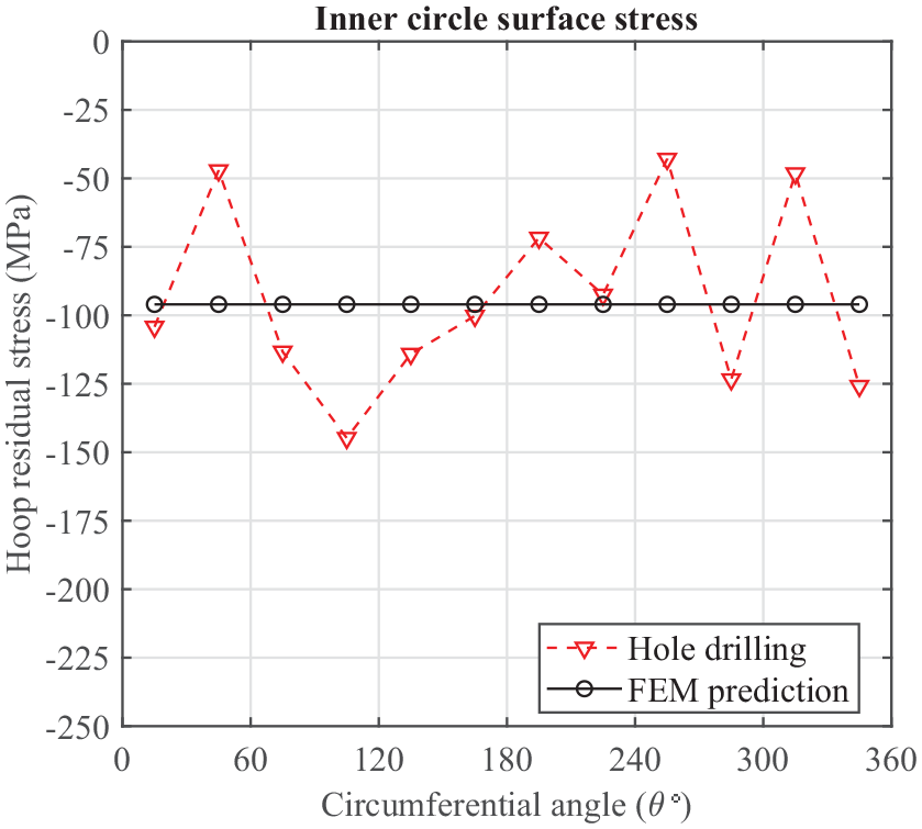
Comparison of the HD and FEM results for the inner surface of the cylinder.
Previous studies20,27 revealed that stress relaxation may lead to macro deformation (opening or closure) at the cut tip when a complete ring or cylinder is split; hence, the effect of section removal on hoop stress was further investigated by employing numerical simulation. Figure 15 shows the hoop stress on the middle plane of the extracted section after the cut. By comparison, in Figure 13, it was evident that the hoop tensile stress was slightly relaxed from 282 MPa to 255 MPa. However, the overall distribution pattern remained similar.

The sectional distribution of hoop residual stress on the middle plane of an extracted section.
The CM result for the extracted section is shown in Figure 16. Compared with the FEM prediction (Figure 15), good agreement was found in the extracted state. The CM also showed a higher stress magnitude at the inner diameter, which validated the interpretation of the FEM prediction. Through the FEM prediction, the HD, and the CM measurement, it was evident that cylinder integrity affected hoop residual stress.

The distribution of hoop residual stress on the middle plane of the extracted cylinder section using the CM.
When using an extracted sample from a cylinder for measurement and interpretation, extra caution is necessary because the original state has been altered. Cylinder hoop stress can also be measured using destructive methods, such as the LRM and slitting. Technologically speaking, the main issue for high-temperature alloys is their difficult-to-cut properties. Consequently, the LRM may not be suitable for their measurement. Slitting and the CM are both applicable, but the latter can provide more detailed distribution feathers; thus, it was selected for the present study.
Residual stress in the forging block
The contour maps of residual stress in the X and Y directions using the CM are shown in Figure 17. The two directions both demonstrated a typical thermal pattern, as the tension in the center was balanced by outside compression. In the X direction, cross-sectional distribution showed an obvious gradient: a peak compressive stress of −258 MPa on the top and bottom surfaces, and a maximum tensile stress of 95 MPa located at the block center but with a lateral position shift (near the edges). In the Y direction, the distribution was similar, but with a lower magnitude in the range of ±100 MPa. Peak tension was observed near the boundary. A similar shift of the center tension was also observed in cold-rolled plates 34 and cold-compressed blocks, 38 in which the vertical load in the thickness direction caused a restricted in-plane plastic flow. This phenomenon may imply a forging load applied to the block, causing an alternation of the in-plane residual stress.

Contour map of the residual stress in the forging block using the CM: (a) X direction and (b) Y direction.
To verify the CM measurement, the full-field residual stress in the block was investigated using the FEM approach, and the results are shown in Figure 18. The final state was still dominated by a thermal effect, although a 1% permanent plastic deformation was applied after quenching. Similar tension shifts were clearly observed in both the X and Y directions due to vertical compression. In addition to the Z direction, a symmetrical but relatively complex distribution was evidently caused by the vertical load. An obvious transition from center compression to surrounding tension was observed. The superposition of thermal and mechanical effects resulted in the alternation of the overall stress field.

Contour map of the residual stress in the forging block using the FEM.
Good agreement was observed between the CM measurement and the FEM prediction for the two cut planes, which demonstrated a powerful ability to reconstruct the area stress using the CM. In this forging case, other mechanical methods, such as slitting and the LMR, can also provide a 1D curve showing an accurate stress gradient, but multiple tests in each direction are required to establish a 2D contour. Additionally, it was likely that a hybrid model, verified via experiment and finite element analysis, could effectively and efficiently establish full-field stress for engineering usage.
The spatial distribution of maximum principal stress indicated that the block boundary exhibited high-level stress, which inevitably led to distortion when the frame structure was milled. This prediction was validated by an actual milling test; therefore, an appropriate model of residual stress is important and necessary for high-precision manufacturing management.
Hybrid method for modeling bulk residual stress
Following the presented case studies, a hybrid method is proposed to predict bulk residual stress in aeronautical components. The idea is to experimentally determine the concerned stress tensor using inverse calculation, numerically simulate the source thermal or mechanical stresses in the manufacturing chain, and finally combine them to model the full-stress field for a specific geometry (Figure 19).

Proposed hybrid method for modeling bulk residual stress in different components.
The advantage of this method is that not all residual stress tensors have to be measured. Combining sufficient measurement and appropriate simulation is enough to provide reliable data. The proposed method was validated for the T-section beam, cylinder, and block. The results indicated that the magnitude and distribution pattern of residual stress could be predicted quite well.
Moreover, the method is a general approach that could be applicable to many types of integral aeronautical components with a high buy-to-fly ratio. In these cases, bulk residual stress is the main cause of shape deviations. Reconstructed stresses can be applied to systematically analyze strategies for predicting or minimizing distortion in manufacturing sequences.
Conclusions
Mechanical relaxation methods (including the LRM, slitting, HD, and the CM), physical diffraction (including the XRD and ND), and multiphysics simulation were used to model bulk residual stress in the present study. Cross-method verification was employed to analyze the reconstructed stress fields in different components with distinct geometries.
The main conclusions are as follows:
Each mechanical relaxation method had advantages and could be the most or least suitable method in different cases. Technically, CM measurement possessed high accuracy, sensitivity, and spatial resolution; thus, it is recommended for residual stress estimation.
Physical diffraction methods are technically powerful but often encounter application limitations. For engineering, they often serve as a limited verification/reference.
Numerical simulation is a general approach for conveniently assessing full-field stress states in engineering components, but reliable results require extra experimental validation.
Based on the investigation results for the T-section beam, cylinder, and forged block, it is evident that thermal and mechanical effects are the main source of bulk residual stress. Through a combination of the experimental CM and numerical analysis, full-field stress can be efficiently determined. This hybrid method for modeling residual stress can be applied for different components to provide a solid data reference for distortion engineering.
Footnotes
Handling Editor: James Baldwin
Declaration of conflicting interests
The author(s) declared no potential conflicts of interest with respect to the research, authorship, and/or publication of this article.
Funding
The author(s) disclosed receipt of the following financial support for the research, authorship, and/or publication of this article: This work was supported by the National Natural Science Foundation of China (Grant No. 51705087) and the China Postdoctoral Science Foundation (Grant No. 2020M683655XB).