
Abstract
Composite-aluminum structures exist in aircraft structures generally. It is easy to cause gap between mating surfaces in composite-aluminum assembled structures with the curing deformation of composite. The composite-aluminum, single-lap, single-bolt joints were utilized to investigate the influence of forced assembly, liquid shim and peelable fiberglass shim on the mechanical properties of assembled structures. A steel gasket that removed the middle part was used in the joint to make a gap. The 3D Digital Imagine Correlation (3D-DIC) system was utilized to measure the strain field of specimens and the progressive damage model was created in ABAQUS. The results show that the shim filling can significantly increase the tension stiffness and peak load of the joint compare with forced assembly. As the shim thickness changes, the effects of the liquid shim and the peelable fiberglass shim on the tensile stiffness and peak load shows different. The liquid or peelable fiberglass shim can reduce the strain value around the hole and the peelable fiberglass shim has a better result than liquid shim. The squeeze between the bolt and composite laminate has a greater impact on matrix damage and fiber-matrix shear damage, while the secondary bending has a greater impact on matrix damage and fiber damage.
Keywords
Introduction
Composite materials have been widely used in aircraft manufacturing with excellent mechanical properties. The composite of largest amount used in aircraft structures is carbon fiber reinforced plastics (CFRP). Composite materials have high specific strength and specific modulus, and they have excellent fatigue resistance and breakage safety. The increase in the proportion of composite materials can reduce the weight and the fuel consumption. The composite use ratio of Boeing B787 reaches 50% while that of Airbus A350 is as high as 52%. 1 With the development of design and manufacturing technology of composite, the use of composite has been extended from secondary bearing components to main bearing components. For example, the central wing box of Airbus A380 is made of composite materials.
Although the proportion of composite materials used in aircraft continues to rise, it still cannot completely replace metal materials. Many components on the aircraft, such as some joints and integrated frames, are still made of metal materials such as aluminum alloys, titanium alloys, and high-strength alloy steels. Until now, the aircraft structure still contains a large number of composite-metal hybrid assembly structures.
Metal components are generally processed by CNC machine tools with high dimensional accuracy. Composite components are mostly formed with molds in autoclaves. Due to the difference in thermal expansion coefficient between fiber and resin, large deformation occurs after the composite member is molded. 2 Therefore, the interference or gap is often generated between the mating surfaces during assembly work. The interference can be eliminated by milling the sacrificial layer on the surface of composite component, or by milling the metal component according to Measurement Assisted Assembly (MAA). As gap is created, the forced assembly or gap filling should be determined according to size of the gap. The preload of fastener can be used directly to eliminate the gap when it is small enough. But it is necessary to fill the shim therein as the gap becomes large, including liquid shim, peelable fiberglass shim, solid shim, or combinations thereof. Gap filling process may create a complex assembly interface in the composite-metal joints, which has an effect on the mechanical properties of the structure. In addition, the shim may be damaged due to tension force, and the generated debris may threaten the structural safety. Therefore, it is necessary to study the influence of gap filling on the mechanical properties of composite-metal hybrid joints. In this paper, the composite laminates and aluminum plates were selected for study.
Many scholars have researched the gap filling in assembly process of aircraft composite components. Flake 3 pointed out that in order to prevent cracks and delamination of composite materials, gaps larger than 0.27 mm (0.005″) should be filled with shim. When the gap is between 0.0762 mm and 0.762 mm (0.003″ and 0.03″), the liquid shim should be applied. The solid shim needs to be added under the premise of engineering permission if the gap exceeds 0.762 mm (0.03″). Randy 4 summarized it is usually filled by liquid shim when the connecting surface contains a step or uneven gap. However, the use of liquid shim is always limited to 0.762 mm (0.03″) or less. Randy also studied a variety of gap filling methods used in JSF fighters, including single shim and mixed shim. Jamie 5 thought that manual gap filling can take a lot of time and waste shim material. In response to this shortcoming, he developed an efficient, automated liquid shimming system and verified the reliability of specific components of the system.
On these bases, it is important to analyze the influence of the gap filling method on mechanical properties of composite structures. Zhai et al. 6 studied the effect of gap filling on the mechanical properties of composite-aluminum joints in experiments. The studies show that the presence of a gap weakens the load bearing performance of the joints. Joints with peelable fiberglass shim have higher tensile stiffness than joints with liquid shim because peelable fiberglass shim has a higher Young’s modulus than liquid shim. Zhai et al. 7 also used a finite element method to study the three-dimensional stress distribution of a composite, single-lap, countersunk bolted joint under tension in forced assembly and gap-filling. Yang et al. 8 studied the model for composite single-lap joints containing gaps and shim. An improved spring-mass model was proposed for the prediction of joint stiffness. Parametric studies show that for every 0.1 mm increase in gap size, the shear stiffness decreases by 1.1%. Yang et al. 9 also investigated the influence of gap and shim on the bending properties of composite joints. The results show that the gap reduces the strength of the joint, and the addition of a shim can make up for this loss. Liu et al. 10 used experimental and simulation methods to study the influence of liquid shim on the mechanical properties of composite-titanium joints. The results show that the breaking load and tensile stiffness decrease with increasing shim thickness. However, this effect is small when the shim thickness is within 0.5–1 mm. Liu 11 also pointed out that the influence of liquid shim on the performance of assembly structure depends not only on the thickness and mechanical properties of the shim, but also on the stiffness of substrate. Comer et al. 12 studied the influence of aviation-grade liquid shim on the mechanical properties of composite-titanium, double-bolt, single-lap joints. The investigation shows that the stiffness of the liquid shim does not decrease, and there is no failure in the contact surface. Hühne et al. 13 used finite element simulation to study the influence of a liquid shim on the mechanical properties of composite joints. A three-dimensional Hashin failure criterion and a continuous parameter degradation model were used in the model. The results show that an increase in the thickness of shim results in a decrease in the critical stiffness. But it has little effect on the ultimate load and design load. Dhôte et al. 14 considered the influence of liquid shim on the mechanical properties of composite, single-lap joints, and composite-aluminum, single-lap joints. The 3D Digital Image Correlation (3D-DIC) method was used to measure the surface strain field of the joint. It is shown that the introduction of a liquid shim amplifies secondary and tertiary bending, thereby increasing out-of-plane deformation of the joint. Cheng et al. 15 investigated the influence of non-uniform gaps and shim on the mechanical properties of aluminum alloy joints. The results show that a shim can reduce the assembly stress of joints and improve joint stiffness and load carrying capacity. The comprehensive performance of the hybrid shim is between the solid shim and liquid shim.
Although many researchers have studied the issue of gap filling, there are still many problems that need further study. In the current gap filling specifications, the allowable gap exists in a narrow range, below 0.06″ (1.532 mm). However, in the actual assembly process, gaps greater than 0.06″ are often generated, and some gaps even exceed 50% of the thickness of the composite laminate. In this case, the assembly structure with gap filling can still be used normally, but it is not clear how much its mechanical properties are affected. Therefore, it is necessary to study the influence of gap size and filling of different shims on the mechanical properties of composite-aluminum joints in a wider gap range. Compared with liquid shim, peelable fiberglass shim has higher elastic modulus and strength. However, the structure of the peelable fiberglass shim is loose and brittle, so it is easy to break when the structure is stressed. This may have a more complicated influence on the mechanical properties of structures. Therefore, it is necessary to make a comparative study on the gap filling behavior of liquid shim and peelable fiberglass shim.
In this paper, the influence of gap filling on the mechanical properties of composite-aluminum, single-lap, single-bolt joint was studied. A steel gasket that removed the middle part was used in the joint to make a gap. The static tensile test was performed using joints containing assembly gaps, liquid shim, and peelable fiberglass shim, respectively. The 3D-DIC strain measurement system was utilized to monitor the three-dimensional strain field of the specimen surface. The effects of the gap-filling on the tensile stiffness, peak load and surface strain distribution of the joint were studied. On this basis, the ABAQUS software was utilized to establish a three-dimensional, progressive damage-based finite element model to analyze the damage and failure of the composite in the tension.
Problem descriptions
Figure 1 shows the basic structure of an aircraft composite wing box. Its components include upper and lower panels, front and rear spars, and three ribs. The panels and the spars are composite laminates, and the ribs are aluminum alloy. The connection between the ribs and the panels is a composite-aluminum hybrid joints. According to the external force of the wing box, the joint is mainly subjected to shearing load. Therefore, it is possible to simplify the composite-aluminum structure as a single-bolt single-lap joint. The single-lap joint lacks lateral support during the tension process and produces a more pronounced secondary bending effect, which is a kind of poor stress state in various connection structures. Using this structure to study the effect of gap filling on joint performance is representative. The joint geometry is designed in accordance with ASTM D5961, 16 as shown in Figure 2.

The structure of composite wing box (Hidden lower panel).
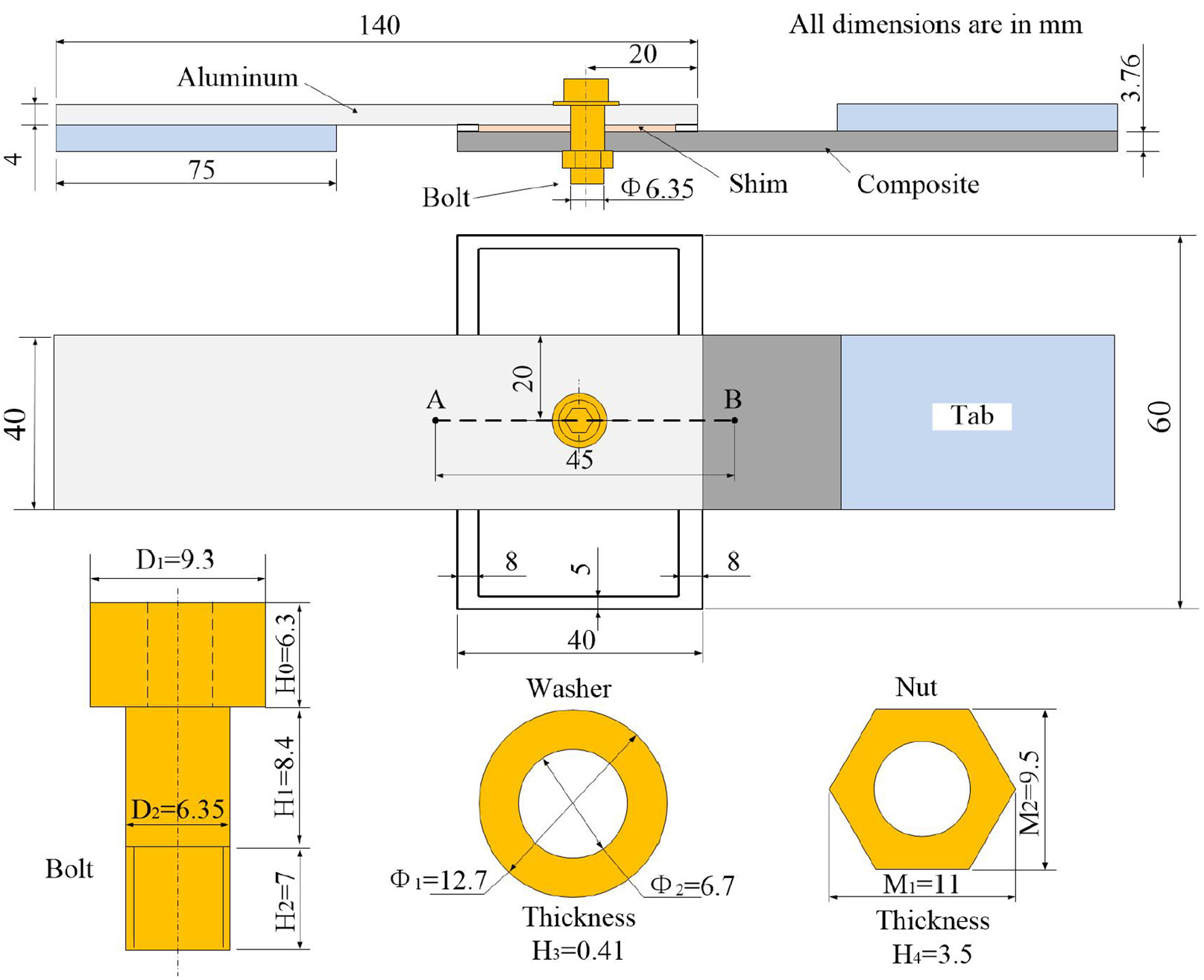
The dimensions of single-lap joint with shim.
Another key issue in the design of tensile specimens is the manufacture of the gap. In Zhai et al. 6 used a numerically controlled machining method to mill a conical gap on an aluminum alloy plate, but this method may weaken the bearing capacity of the aluminum alloy plate. In Cheng et al., 15 the gap was made by cutting the aluminum plate into a shape of a spline curve via wire cutting.
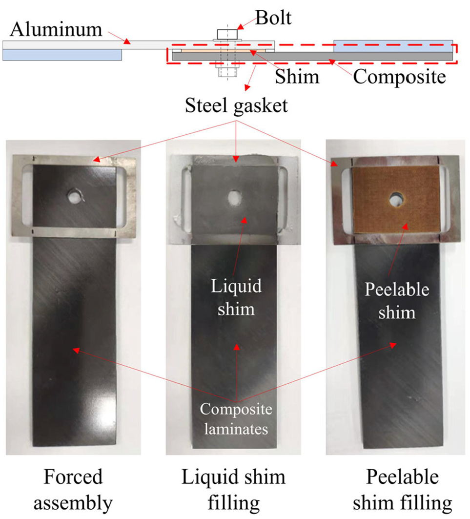
In the present work, a steel gasket that removed the middle part was used in the joint to make a gap, as shown in Figure 3. Among them, the steel gasket removed the material of the middle portion by a stamping process, leaving only the edge portion. In manufacturing the specimen, the steel gasket was bonded to the composite laminate using an adhesive to create a gap. Various types of shim can be filled in this gap to study their influence on the mechanical properties of the joint. In forced assembly, the presence of steel gasket caused bending deformation of composite laminate when the bolt was tightened. During tension process, the interaction between bolt and composite laminate was not affected by steel gasket. In liquid shim or peelable fiberglass shim filling condition, the thickness of steel gasket can be used to accurately control the thickness of shim to ensure the accuracy of experimental model. Likewise, the interaction between bolt, shim and composite laminate was not affected by steel gasket.
The construction of the gap in specimen.
In the composite-aluminum hybrid joints, the use of aluminum gasket or composite gasket in making the assembly gap was more in line with the actual situation. However, it was found in practice that buckling deformation was prone to occur when aluminum were used to make gaskets. Moreover, its dimensional stability was poor and the accuracy of the gap size cannot be guaranteed. Composite gaskets were prone to have delamination damage during processing, which affected dimensional accuracy. In addition, the composite gasket can produce large deformation in molding process. The dimensional error in the thickness direction was large, which was also not suitable for manufacturing assembly gaps. The steel gaskets had good dimensional stability and they were convenient machining, which met the requirements of experimental research. Therefore, steel gaskets were used to make the gap in this paper.
Experimental design
Materials and properties
The tension joints were made of typical materials utilized in aircraft. Carbon fiber epoxy laminates were made of prepreg 977-2 with the lay-up of [45°/90°/–45°/0°/90°/0°/–45°/90°/45°/–45°]s. The composite was laminated with 20 layers and the thickness was 3.76 mm. The mechanical properties are shown in Table 1. 17 The aluminum alloy grade was 7075 with the thickness of 4 mm. The Young’s modulus is 72 GPa, and the Poisson’s ratio is 0.33. In order to ensure the precision of the specimen manufacturing, the cutting and drilling of the composite laminate and the aluminum plate were completed by CNC machine tools. Diamond-coated carbide tools were utilized in cutting composite laminates to achieve high-quality bolt hole drilling through process parameter control. This method minimized the delamination, tearing and burrs around the composite hole while meeting dimensional accuracy. According to the size requirements of bolt, the diameter of bolt shank must be between 6.3246 mm and 6.3373 mm (0.2490″ and 0.2495″). The diameter of bolt hole must be between 6.35 mm and 6.38 mm according to experimental requirements. The measurement results showed that the diameter of bolt shank and bolt hole met the size requirements, which can ensure a clearance fit between them. The clearance between the bolt shank and hole was about 50 μm, which was complied with the aircraft assembly process specification for less than 1% of the hole diameter. 18 The high-strength bolts, nuts and washers utilized in the research were made of Ti6Al4V. The Young’s modulus is 110 GPa and the Poisson’s ratio is 0.29. According to the assembly process regulations, the 6.35 mm diameter bolt used in the experiment had a rated preload of 8000 N. The empirical formula between tightening torque and preload is T = kFd, where T represents the tightening torque, k represents the torque coefficient, F represents the preload, and d represents the nominal diameter of the bolt. According to the results of the experimental measurement, the value of the torque coefficient k was about 0.148. So the torque should be controlled at about 7.5 Nm by a fixed torque wrench to ensure that the preload was 8000 N. This method ensured that the bolt had sufficient preload to achieve a reliable connection of the joint. Due to the existence of the gap, the composite laminate and the aluminum plate may have a certain degree of bending deformation after the bolt torque was applied, which was consistent with the actual assembly process.
Composite material properties of 977-2.

The liquid shim and peelable fiberglass shim were studied in experiments. The liquid shim EA9394 was a two-component epoxy-based shim. Its material properties are shown in Figure 4. 10 It contained two components, an epoxy resin matrix and a curing agent. The two components were first uniformly mixed with a mass ratio of 100:17. Then the mixture should be applied to the composite laminate. Since the gap was created using steel gasket in the early stage, the accuracy of the shim thickness can be ensured by the steel gasket when manufacturing the liquid shim. The gap filling method stated that when shim is applied between composite components, it can only be bonded to one of the component and cannot be bonded to the other one. Therefore, after the liquid shim was applied to the composite laminate, it was necessary to cover the shim with a film to prevent it from bonding to the aluminum plate. This was achieved by using an aluminum plate to gently squeeze the liquid shim to remove the remaining shim material. It could also ensure that the liquid shim was sufficiently filled in the gap to eliminate any air bubbles or voids that may be present. After curing at room temperature for 168 h, the film can be removed, and the composite laminate with the liquid shim and the aluminum plate were clamped on a CNC machine to make holes. Finally the specimens were cleaned and bolted.

Stress-strain relationship of EA9394.
Peelable fiberglass shim was laminated fiberglass fabric. The material properties are shown in Table 2. 7 When a peelable fiberglass shim was utilized, a shim of a certain thickness was peeled off according to the required thickness. Then it was cut into a desired shape. The peelable fiberglass shim was bonded to the composite laminate using adhesive in manufacturing the tensile specimen. Then the hole was made using a CNC machine tool. Finally the fixed torque wrench was utilized for bolting after cleaning.
Material properties constants of peelable fiberglass shim.

Experimental device and testing group
The tensile test was carried out using a SANS universal testing machine. The maximum tensile load of the testing machine was 100 kN and the relative error of test force and displacement were controlled within ±0.5%. The specimen was fixed on the experimental machine using a collet before the experiment. The lower clamp was kept fixed during tension process, and the upper clamp was pulled by the beam to stretch the specimen at a speed of 2 mm/min. The tension process was stopped when the tensile load was reduced by 20% compared to the peak load. In this case, it was almost certain that the joint reached the peak load.
Flake 3 summarized the liquid shim should be used when the gap is 0.005–0.030″ (0.127–0.762 mm), while the liquid shim and peelable fiberglass shim should be used together when the gap is more than 0.030″ (0.762 mm). But he did not explain the reasons. The gaps constructed in the present work ranged from 0 mm to 2.0 mm, which were 0, 0.4, 0.8, 1.2, 1.6, and 2.0 mm respectively. The thickness ratio of the shim to the composite laminate was in the range of 0%–53.20%. Three different cases were investigated experimentally, including the specimen with a gap, a liquid shim and a peelable fiberglass shim. The test groups and their abbreviations are shown in Table 3. Each test group contains three joints.
Test groups and their abbreviations.

3D-DIC strain measurement system
The strain field of the joint surface was measured using a 3D-DIC strain measurement system, as shown in Figure 5. This system is manufactured by Correlated Solutions Inc. (CSI). It can analyze the change of speckle image on the surface of specimen in tension, and calculate the displacement and strain field on the surface of joint. So this method is widely used in the study of mechanical properties of composite materials.6,14

Tensile testing machine and 3D-DIC strain measurement system.
The measurement system consists of two charge coupled device (CCD) cameras groups (12 million pixels) with a lens of 25 mm focal length. The light source is used to increase brightness of the specimen, and a tripod is used to fix and adjust the position of the camera. The photo is taken every 3 s in tension. Two groups of camera systems were used simultaneously during the tension process to measure the strain field of the composite laminate and aluminum plate, respectively. The displacement of the joint was obtained by measuring the displacement between point A and point B, as shown in Figure 2.
Before the experiment, the speckle should be firstly made on the specimen. The surface of the specimen needs to be cleaned with acetone to remove grease and dust. A white matte primer was then applied. After the primer was dried, black speckles were evenly printed on the specimen using a speckle making tool. According to the size of the camera pixel and the field of view, speckles with a diameter of 0.33 mm were selected while the speckle density over the surface of specimen was about 50%.
Finite element model
Elements, mesh and boundary conditions
The finite element model utilized in the study was established in ABAQUS/Standard. Both ends of the tensile specimen were clamped on the fixture of the testing machine in tension, so the clamping end was omitted when the FEM model is established. At the same time the bolts, nuts, and washers were created as one part to reduce the contact surface in the model, improve the convergence and calculation efficiency of the model.
Each part was modeled using reduced, linear eight-node, three-dimensional, solid elements, C3D8R. The composite laminate was divided into one element for each layer along the thickness direction. The stress concentration was intensified in area around the hole of composite laminate, so the damage and failure of composite mainly occurred in this area. Therefore, the local mesh refinement was applied to the area around the hole. The mesh of each part is shown in Figure 6. The performance parameters of each material are shown in section 3.1.
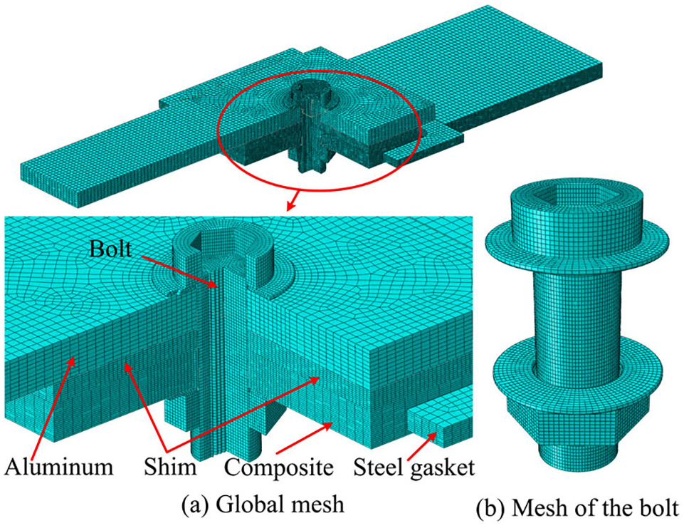
FEM mesh of the bolted joints.
The shim was only bonded with the composite laminate, while there was no bonding relationship with the aluminum plate. Therefore, the shim and the composite laminate were set in a tied relationship. Other contact relationships in the model were set in surface-to-surface contact. The penalty friction was used to define the tangential behavior, while the hard contact method was used to define the normal behavior. The friction coefficient between each material pair in contact was set to: titanium and composite: 0.16, 19 aluminum and composite: 0.2, titanium and aluminum: 0.2.20,21 There were four surface-to-surface contacts and a tied relationship in the model, as shown in Figure 7.

Contact pairs in FEM model.
The boundary conditions of the model are shown in Figure 8. Three translational degrees of freedom at one end of the specimen were fixed (UX = UY = UZ = 0). The other end was fixed to two degrees of freedom (UY = UZ = 0), and a displacement of 5 mm was applied in the UX direction. In order to improve the convergence of the model, light springs were set on the upper and lower end faces of the bolts, and on the end faces of the composite laminate and aluminum plate, as shown in Figure 8. The effect of the stiffness of the light spring on the mechanical properties of the joint was considered in the finite element model. The analysis results are shown in Table 4. The experimental groups N, G0.4, L0.4, and P0.4 were selected, and the peak loads obtained from the experiments and the finite element models were compared. The results showed that the light spring stiffness has little effect on the peak load of the joint. For most experimental groups, the simulation results are closest to the average of the experimental results when the light spring stiffness is 0.2 N/m. Therefore, the stiffness of the light spring in the finite element model was set to 0.2 N/m. There was no lateral support, so the specimen had a secondary bending effect during tension process.

The boundary condition of the FE model.
Effect of light spring stiffness on peak load of joint.

The bolt preload was applied by Bolt Load function module in ABAQUS. Firstly, a 10 N bolt preload was applied in the first analysis step, so that the contact relationships were established smoothly, which was convenient for the convergence of the simulation calculation. In the second analysis step, the preload was increased to the experimental value of 8000 N. Finally, a 5 mm uniaxial displacement was applied in the third analysis step.
Progressive damage model
Progressive damage analysis is widely used in the study of mechanical properties of composite structures. During the loading process, the element should be evaluated according to the failure criterion to determine whether it failed after each incremental step, thereby adjusting the material properties. As the element failed, the stiffness parameters need to be reduced according to the stiffness degradation criterion to reflect the reduction of the load bearing capacity. The calculation was then performed for the next incremental step until the final analysis was complete. Therefore, the establishment of a progressive, damage-based finite element model required the selection of failure criteria and stiffness degradation criteria. 22
Researchers proposed multiple failure criteria for composite materials, such as the maximum stress criterion, Hill 23 and Tsai 24 criterion, Hoffman 25 criterion, Tsai anf Wu 26 criterion, Yamada and Sun 27 criterion, Hashin 28 criterion, Chang and Chang 29 criterion, Chang and Lessard criterion, 30 Puck criterion, 31 and so on. Some researchers improved these failure criteria to better simulate actual conditions.32–35 The error between the results of the progressive damage method and the experimental results can be controlled within a small range, which implies the applicability of the method in studying the influence of gap filling on the damage of composite laminate.
Olmedo and Carlos 36 extended the two-dimensional failure criterion proposed by Chang-Lessard 30 to three-dimensional. They chose this failure criterion to build a simulation model to study the failure process of single-lap bolted composite connectors. In addition, this criterion also considered the nonlinear relationship between in-plane shear stress and shear strain, which may be caused by matrix cracking.
This failure criterion includes fiber tensile and compressive failures, matrix in-plane tensile and compressive failures, matrix out-of-plane tensile and compressive failures, and fiber-matrix shear failures. In the following formula, σ11 is stress along the fiber direction, σ22 is the stress along the matrix direction, σ33 is the out-of-plane normal stress, τ12 is the in-plane shear stress, τ13 and τ23 are the out-of-plane shear stresses. XT and XC are longitudinal tensile and compressive strength, YT and YC are transverse tensile and compressive strength, ZT and ZC are out-of-plane tensile and compressive strength, S12 is in-plane shear strength, S13 and S23 are out-of-plane shear strength.
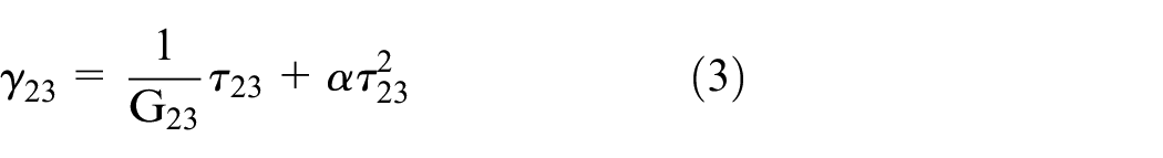
There is a nonlinear relationship between in-plane shear stress and shear strain of composite laminates. The relational formula formulated by Hahn and Tsai 37 is:

where α is a constant, and its value is determined by experiment.
Since the nonlinear response of the composite laminate is mainly determined by the performance of the matrix material, the following relationship can also be drawn for the out-of-plane stress and strain:

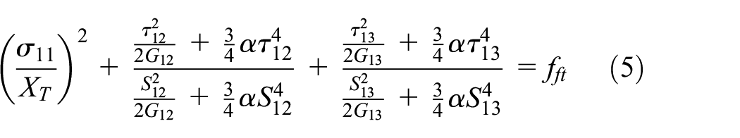
The failure criteria used in this paper mainly consider fiber damage, matrix damage and fiber-matrix shear damage. Specifically, it includes fiber tensile failure, fiber compressive failure, matrix in-plane tensile failure, matrix in-plane compressive failure, matrix out-of-plane tensile failure, matrix out-of-plane compressive failure, and fiber-matrix shear failure.
(1) Fiber tensile failure (σ11≥0)

where fft is index of fiber tensile failure,
(2) Fiber compressive failure (σ11<0)
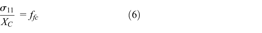
where ffc is index of fiber compressive failure.
(3) Matrix in-plane tensile failure (σ22≥0)
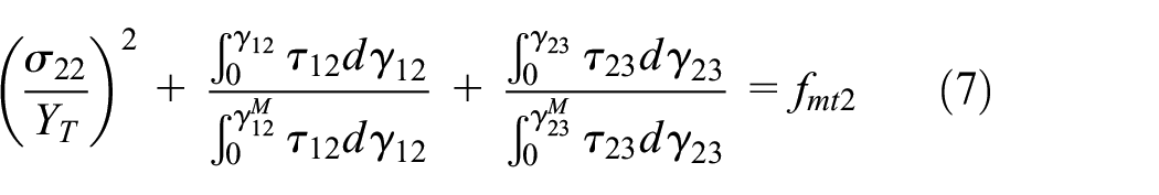
where fmt2 is index of matrix in-plane tensile failure,
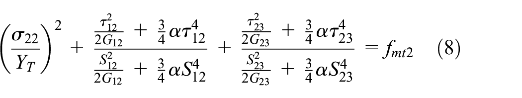
(4) Matrix in-plane compressive failure (σ22<0)

where fmc2 is index of matrix in-plane compressive failure. By considering the nonlinear relationships in equations (1) and (3), equation (9) can be written as:

(5) Matrix out-of-plane tensile failure (σ33≥0)

where fmt3 is index of matrix out-of-plane tensile failure. By considering the nonlinear relationships in equations (2) and (3), equation (11) can be written as:

(6) Matrix out-of-plane compressive failure (σ33<0)
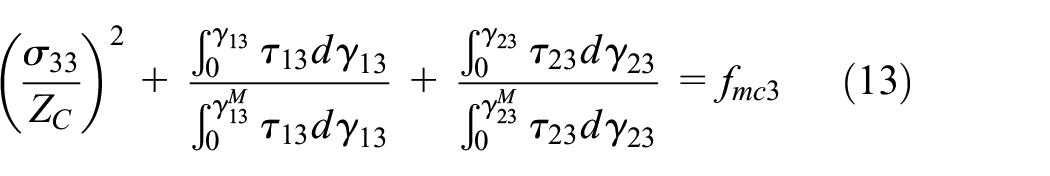
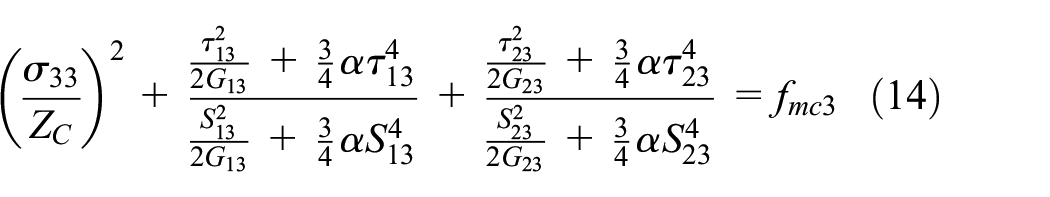
where fmc3 is index of matrix out-of-plane compressive failure. By considering the nonlinear relationships in equations (2) and (3), equation (13) can be written as:
(7) Fiber-matrix shear failure

where fs is index of fiber-matrix shear failure. By considering the nonlinear relationships in equations (1) and (2), equation (15) can be written as:

After judging the failure of some elements in the composite laminate according to the failure criterion, the stiffness of the element needs to be reduced. The mechanical properties of the joints change due to the damage of some elements. Therefore, the corresponding stiffness degradation criterion needs to be selected to adjust the loading bearing capacity of the joint. Many researchers proposed different stiffness degradation criteria. Chang et al. 38 thought that after the failure of the element, it no longer possesses load bearing capacity, and the stiffness is directly reduced to 0, so the stiffness reduction factor is 0. Tan and Perez 39 believed that the fiber and matrix still have certain stiffness after damage failure, and the stiffness reduction factor is 0.1. Hühne et al. 13 studied the strength of composite joints with a liquid shim, and adopted two degradation methods, including the constant stiffness degradation criterion and the continuous stiffness degradation criterion. The degradation criterion adopted in the present work was further improved by Camanho and Matthews 40 on the basis of Tan, 41 as shown in Table 5.
Stiffness degradation rule in USDFLD.
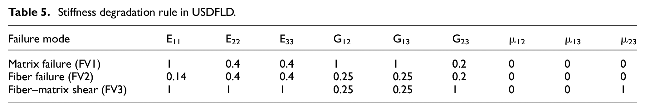
USDFLD is a subroutine provided in ABAQUS that can define field variables. According to the failure criterion and material degradation criterion selected in this paper, three state variables SDV1, SDV2, and SDV3 were obtained using the USDFLD subroutine, which respectively represented matrix damage, fiber damage, and fiber-matrix shear damage. A total of three field variables were used in the USDFLD, including FV1 (matrix damage), FV2 (fiber damage), and FV3 (fiber-matrix shear damage). The damage state variables of elements in composite laminates were analyzed in this paper. Because they can not only show the element completely damaged, but also the damage degree of the elements that was not completely damaged. Among them, matrix damage included in-plane damage and out-of-plane damage, and fiber damage included fiber tension and fiber compression damage. During the calculation of the finite element model, the USDFLD subroutine was used to assign values to the solution-dependent state variable SDVi (i = 1–3). At the beginning of each incremental step, the USDFLD subroutine read the stress and other data of the element integration point through the GETVRM function. Then the subroutine used the corresponding failure criterion and stress value in element integration point to calculate the damage index, and assign this value to the solution-dependent state variable SDVi (i = 1–3). When the SDV is less than 1, it means that the element is not completely damaged and still has the bearing capacity. At this time, the field variable FV is 0. When the SDV is equal to 1, it means that the element is completely damaged and the material stiffness is reduced. At this time, the FV is also equal to 1.The reduced stiffness was recombined, and the next iterative calculation was performed until loading stopped or the material completely failed. The analysis process is shown in Figure 9.

The flow chart of progressive damage calculation.
Results analysis and discussion
Load-displacement curves
Figures 10 to 12 are load-displacement curves obtained from the joints under forced assembly, liquid shim filling and peelable fiberglass shim filling, respectively. By analyzing the load-displacement curves of the joint, it shows that the tension process can be roughly divided into five stages, no-slip section, slip section, full contact section, damage section and final failure section, exactly the same as reported 19, as seen in Figure 13. In the no-slip section, the joint relies on the static friction between the two plates to bear the external load. At this time, the tensile stiffness of the joint is relatively large. When the external load exceeds the maximum static friction that can be provided by the two plates, a relative slip occurs and the curve enters the slip section. In this stage, the displacement increases significantly whereas the load increases less. The length of the slip section depends on the size of the clearance between the bolt shank and the hole. When the contact occurs between the bolt shank and the hole, the curve enters the full contact section. The bearing capacity of the joint mainly depends on the contact area of the bolt shank and the hole at this time. The carrying capacity increases with the increasing contact area. Due to the clearance between the bolt shank and the hole, the bolt rod can tilt in tension and form a severely squeezed area with the composite laminate and aluminum plate, as shown in Figure 14. Among them, areas a and b are severely squeezed areas on the aluminum alloy plate, and areas c and d are areas where the composite laminate is severely squeezed. The damage of the composite material laminate is also mainly generated in areas c and d. With the continuous enhancement of the squeezing effect of the bolt shank and the hole, the composite laminate begins to be damaged, and the curve enters the damage section. In this section, the tensile stiffness of the joint is reduced, but the joint does not lose the bearing capacity. When the damage accumulates to a certain extent, the joint completely loses its bearing capacity and the load is significantly reduced. At this time, the joint enters the final failure section.

Load-displacement curves of forced assembly.

Load-displacement curves of liquid shim filling.
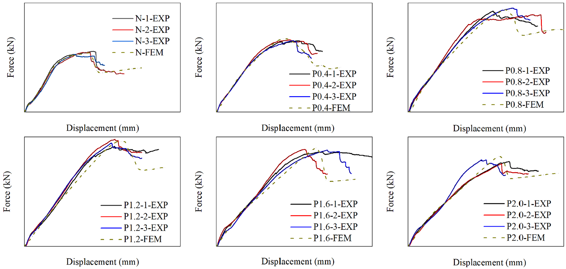
Load-displacement curves of peelable fiberglass shim filling.

Five stages of the load-displacement curve.
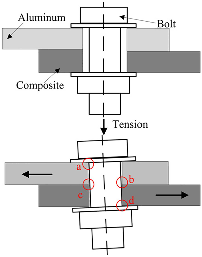
The contact between the bolt shank and hole in tension and the severely squeezed area.
Figure 15 is the tensile stiffness and peak load obtained from experiments and FEM results. Due to the manufacturing error and experimental error of the tensile joint, there was a difference between the three results of each test group. It can be seen from the results that the standard deviation of the peak load and tensile stiffness obtained in the experiment is within an acceptable range. The stiffness K0 of the joint is calculated according to formula 17, 13
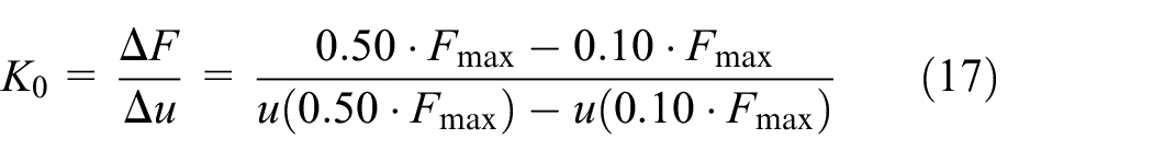
the Fmax represents peak load and u represents displacement.
Tensile stiffness and peak load of the specimens.
It can be seen from the results that as the gap increases, the tensile stiffness and peak load of the specimen decrease continuously. The average peak load of the specimens with gaps in 0.4, 0.8, 1.2, 1.6, and 2.0 mm decrease by 10.17%, 10.35%, 13.72%, 23.33%, 28.23% compare with the matched group, respectively. The average values of tensile stiffness are reduced by 9.08%, 25.90%, 51.45%, 52.41%, 55.25%, respectively. The results of the finite element simulation also conform to this rule. The specimen can bend under the preload when the bolt is installed due to the assembly gap as shown in Figure 16. Therefore, the positive pressure provided by the bolt to the tensile specimen is reduced. In addition, the presence of the gap can also result in a reduction in the contact area and friction between the two plates. These two factors lead to a decrease in tensile stiffness of the joints during the non-slip stage. In the contact stage, the stiffness of the specimen mainly depends on the contact area between the bolt shank and the hole. The specimen has obvious bending deformation during bolt installation, and the contact area between the bolt shank and the hole is significantly reduced. So the stress concentration is intensified during the tension process. Therefore, the stiffness and the peck load of the specimen were reduced. In general, the tensile stiffness and peak load of the tensile specimen are continuously reduced as the gap increases.

The specimens with gaps have obvious bending deformation after the bolts are tightened.
It can be seen from the liquid shim filling results that the tensile stiffness and peak load of the specimens are higher than those of forced assembly. As the thickness of the liquid shim increases, the tensile stiffness decreases while the peak load increases. The deformation of the specimen is reduced when the bolt is installed after filling the liquid shim. During the tension process, the contact area between the bolt shank and the hole is increased, so the stress concentration is obviously weakened. Therefore, the tensile stiffness and peak load are both greater than those of forced assembly. The aluminum plate can still maintain a large contact area with the bolt shank after the secondary bending of the specimen during the tension process due to excellent elasticity. In addition, the liquid shim also has a certain load carrying capacity. So as the thickness of the liquid shim increases, the peak load of the specimen also increases. Although the increase of the shim thickness results in a more severe load eccentricity, it tends to decrease the peak load. However, the effect of load eccentricity is not obvious, and the peak load still shows an upward trend. The load eccentricity results in a continuous decrease in the tensile stiffness of the tensile specimen. Therefore, as the thickness of the liquid shim increases, the peak load of the tensile specimen increases while the tensile stiffness decreases.
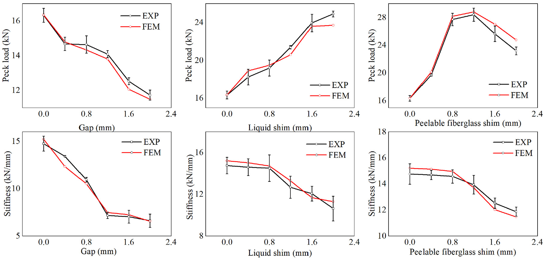
In the results of peelable fiberglass shim filling condition, it can be seen that the tensile stiffness and peak load of the specimen are higher than those of the forced assembly. As the thickness of the peelable fiberglass shim increases, the peak load of the tensile specimen increases firstly and then decreases. The peak load reaches the maximum value when the peelable fiberglass shim thickness is 1.2 mm. The tensile stiffness of the specimen decreases continually with increasing shim thickness. After filling the peelable fiberglass shim, the deformation of the specimen during bolt installation is significantly reduced, and the contact area between the bolt shank and the hole increases. Therefore, the tensile stiffness and peak load are higher than those of forced assembly. During the tension process, the peelable fiberglass shim and the bolt shank are contacted so as to bear the applied load. However the peelable fiberglass shim is a sheet-like glass fiber fabric. The local delamination or tearing may occur in tension when the thickness is more than 1.2 mm, as shown in Figure 17. Thereby it can weaken the load bearing capacity of the joint. At this time, the load eccentricity plays a leading role, resulting in a decrease in the peak load. The tensile stiffness of the specimen decreases with the shim due to the load eccentricity. From the experimental results, it can be seen that the peelable fiberglass shim is easy to tear during the tension process when the thickness is more than 1.2 mm. This can adversely affect the mechanical properties of the joint. However, there is not obvious damage be found in the liquid shim in experiment. So the liquid shim has better resistance to breakage than the peelable fiberglass shim. It can be seen from Figure 14 that the surface of composite laminate in contact with the nut produced delamination damage. This may be because a strong squeezing effect is generated between the nut and the composite laminate due to the inclination of the bolt, resulting in delamination damage to the composite.
Damage of tensile specimen.
It can be seen from the results analysis that the presence of the gap significantly reduces the tensile stiffness and peak load of the composite-aluminum, single-lap, single-bolt joint. Therefore, it is firstly recommended to reduce or even eliminate the assembly gap in the actual assembly process. Compared to forced assembly, liquid shim filling significantly increases the tensile stiffness and peak loads of the specimen and improves the mechanical properties of the structure. Although the peak load of the specimen increases with the increasing thickness of liquid shim, the tensile stiffness decreases continuously. Therefore, the thickness of the shim is not recommended to be as large as possible. It is necessary to select and judge the liquid shim thickness according to the strength and stiffness requirements of the structure. The peelable fiberglass shim is a layered glass fiber fabric having a higher stiffness and strength than the liquid shim. As the shim thickness increases, the peak load of the specimen increases continuously and the tensile stiffness decreases when the thickness is less than 1.2 mm. At this time, the gap-filling method should be selected and evaluated according to the strength and stiffness requirements of the structure. When the thickness of the peelable fiberglass shim is greater than 1.2 mm, the shim on the side of the bolt hole may be delaminated or torn due to partial extrusion. At this point, the peak load and the tensile stiffness decrease. Therefore, the gap larger than 1.2 mm should not be separately filled by the peelable fiberglass shim.
The liquid shim has excellent fluidity and can be filled in irregular gaps in actual use. The peelable fiberglass shim has high strength and stiffness, but it is not suitable for filling irregular gaps, and it is not suitable for use alone when the gap is larger than 1.2 mm. Therefore, the liquid shim can be mixed with the peelable fiberglass shim for gap-filling when the gap is larger than 1.2 mm. In this way, the complete filling of the irregular gap can be ensured, and the structure can obtain higher mechanical properties than single shim gap filling.
Strain state around the hole in a composite laminate
The 3D-DIC device was utilized to measure the strain field of the composite laminate and aluminum plate simultaneously in the experiments. The measurement results show that the strain value of the aluminum plate is smaller than that of the composite laminate. Figure 18 shows the surface strain field of aluminum in condition of gap and shim thickness in 2.0 mm under a load of 16 kN. The tensile load in forced assembly is less than 16 kN, so the peak load is selected for comparison. The Figure shows that compared to the case of forced assembly, the strain value around the hole of the aluminum plate are reduced after the shim is filled. But the difference between filling liquid shim and peelable fiberglass shim is not obvious. The surface strain value of the composite is larger than that of aluminum plate. And a serious stress concentration occurs around the hole in the composite laminate during the tension process. What’s more, the failure of the tensile specimen also occurs around the hole. Therefore, it is necessary to study the influence of the gap filling on the strain distribution around the hole in composite laminate.

Strain field of aluminum with gap or shim thickness of 2.0 mm.
Figures 19 to 21 show the strain distribution around the hole of the composite laminate in forced assembly, liquid shim filling, and peelable fiberglass shim filling, respectively. For the convenience of comparison, the strain field with a load around 16 kN is selected for analysis. In the forced assembly experiment, since the peak load of the partial tensile specimen is lower than 16 kN, the strain field corresponding to the tensile specimen reaching the peak load is selected for analysis.

Strain field around composite hole in forced assembly.

Strain field around composite hole with liquid shim.

Strain field around composite hole with peelable fiberglass shim.
The experimental results of forced assembly show that the strain field around the hole enhances with the gap. As the gap thickness increases, the load eccentricity increases continuously, and the degree of secondary bending of the composite laminate increases during the tension process. Therefore, the strain field around the hole of the composite laminate continuously enhances, reflecting the increase in the stress concentration around the hole.
It can be seen from the results of the liquid shim filling that the strain value around the hole of the composite laminate increases with the shim thickness. As the increasing of liquid shim thickness, the load eccentricity and secondary bending of the specimen also enhance, so the stress concentration at the edge of the bolt hole increases. However, the strain field around the hole of specimen with liquid shim is generally less severe than that of forced assembly. This indicates that liquid shim filling can significantly reduce the stress concentration around the hole in the composite laminate.
It can be seen from Figure 21 that the strain value around the hole in the composite laminate increases with the thickness of peelable fiberglass shim. This rule is similar to that of liquid shim filling. However, compared with the liquid shim filling, the value of strain around the hole is smaller for the peelable fiberglass shim. This may be because the structure of the peelable fiberglass shim thickness is loose. When subjected to bolt preload, a certain degree of compression may occur in the thickness direction. Thereby, the degree of load eccentricity and secondary bending is reduced, and the stress concentration around the hole is reduced to some extent.
Progressive damage around the hole in composite laminate
The tensile process of the joints is roughly divided into five stages. In the first stage, the joint can rely on the friction between the two plates to bear the external load. The relative sliding occurs between the two plates when the friction is not enough to withstand the applied load, and at the same time the bolt begins to tilt. From the third stage, the bolt shank comes into contact with the wall of hole. Composite laminates begin to suffer damage and their stiffness continues to degrade until the joint eventually fails. By analyzing the three state variables SDV1, SDV2, and SDV3 during the tension process, the damage and failure of the composite laminate can be analyzed and the influence of different shims can be compared.
Figure 22 shows the damage around a hole in a composite laminate under different loads in a joint with 0.8 mm liquid shim. It can be seen from the result that various types of damage around the hole of the composite laminate continue to grow with the increase of the load, but the generation area and change behavior of these types of damage are different. As the load increases, the inclination of the bolt also increases. The bolt shank is firstly pressed against the areas A and E around the hole, so the matrix damage initiates in these two spots. With further increase of the load, the matrix damage at A has continued to grow. In the thickness direction, the damage continuously expands from the surface layer to the inner layer, and on the upper surface, it expands from the inside of the hole to the periphery of the hole. Coupled with the influence of the secondary bending, the matrix damage gradually expands from areas A, E to areas B, C, and D. The squeezing effect of the bolt shank on the hole wall and the secondary bending effect are the main influencing factors of matrix damage.

Damage development process around the hole in composite laminate.
Analysis of the evolution of SDV2 shows that the fiber damage firstly occurred in areas B and E. The fiber damage occurs in area B firstly due to the inclination of the bolt shank and its squeezing of the hole wall of the composite laminate. At the same time, the secondary bending in the tension process causes fiber damage in area C. With the increase of the load, the fiber damage gradually expanded from area C to area D. It mainly develops along the fiber direction, while perpendicular to the fiber direction during the expansion process. However, the fiber damage in area B does not expand significantly. This indicates that the secondary bending has a greater impact on fiber damage than matrix damage in tension process.
According to the analysis of evolution of SDV3, the fiber-matrix shear damage first occurs in areas A, B, and E. It is mainly caused by the squeeze between bolt shank and hole wall of the composite laminate. With the increase of load, the fiber-matrix shear damage mainly expands outward from areas A and B, while area E did not change significantly. This shows that compression of bolt shank against hole has a dominant role in fiber-matrix shear damage, and the secondary bending effect has no obvious effect.
In order to compare the influence of the thickness and the type of shim on the damage around the hole of composite laminate, the damage of each specimen at a tensile load of 16 kN is selected for analysis, as shown in Figure 23. Among them, Figure 23(a) to (c) respectively show the matrix damage, fiber damage and fiber-matrix shear damage obtained by finite element analysis. Figure 23(d) shows the damage around the hole of the composite laminate from three experimental groups N0.8, L0.8, and P0.8. In the case of forced assembly, the degree of various damages around the hole of the composite laminate increases slightly with the increase of the gap, but the change is not obvious. In the case of filling liquid shim or peelable fiberglass shim, both the matrix and fiber damage degrees around the holes are reduced, but the fiber-matrix shear damage does not show much difference than forced assembly. In the case of peelable fiberglass shim filling, the matrix damage, fiber damage, and fiber-matrix shear damage around the hole of the composite laminate are smaller than those in the liquid shim filling, especially when the gap is large. This indicates that the peelable fiberglass shim can better inhibit the expansion of damage in large gaps. This may be attributed to the higher strength of the peelable fiberglass shim, allowing it to bear a greater load in tension. With the increase of shim thickness, the change of various types of damage is not obvious, and it is basically maintained at a relatively stable level.

The failure around hole in composite laminate: (a) matrix failure, (b) fiber failure, (c) fiber-matrix shear failure, and (d) damage to the hole of the composite laminate.
Conclusions
In this paper, the effect of gap filling on the mechanical properties of composite-aluminum joints was studied. The composite-aluminum, single-lap, single-bolt joints were built by putting steel gaskets that removed the middle part in joints. The progressive damage-based finite element model was established by using the USDFLD subroutine provided in ABAQUS. The results of the finite element model agree well with the experimental results. Following conclusions have been drawn from the present work:
In the case of forced assembly, the tensile stiffness and peak load of the specimen continue to decrease as the gap increases. Shim filling can significantly increase the joint tensile stiffness and peak load. For liquid shim filling, the tensile stiffness of the specimen decreases while the peak load increases as the shim thickness increases. For peelable fiberglass shim filling, the peak load of the specimen firstly increases and then decreases as the thickness of the shim increases, reaching a peak value when the thickness of the shim is 1.2 mm. The tensile stiffness of the specimen is reduced with increasing shim thickness. The peelable fiberglass shim may be delaminated or torn due to partial extrusion when the thickness is greater than 1.2 mm. This can adversely affect the mechanical properties of the joint, with both the peak load and the tensile stiffness decreased. Therefore, the gap larger than 1.2 mm should not be separately filled by the peelable fiberglass shim.
With the increase of the gap size or shim thickness, the strain field around the hole in composite laminate is enhanced continuously, and the strain concentration increases accordingly. This is mainly due to the increasing load eccentricity and secondary bending. Compared to forced assembly, liquid or peelable fiberglass shim filling can reduce the stress around the hole. The peelable fiberglass shim has a better performance than liquid shim, which may be related to the higher strength and elastic modulus of the peelable fiberglass shim and looser structure than the liquid shim.
Three types of damage around the hole of the composite laminate show different evolution rules. As the tensile load increases, the damage continues to expand. Squeezing between the bolt and the composite laminate has a greater impact on matrix damage and fiber-matrix shear damage, while the secondary bending has a greater impact on matrix damage and fiber damage. Compared to forced assembly, shim filling can significantly reduce the damage around the hole. For the specimens with different shim thicknesses, the degree of damage around the hole in the composite laminate has hardly changed.
The conclusions of this paper can provide references for the assembly of aircraft composite components. First of all, the assembly gap has an adverse effect on the mechanical properties of the composite-aluminum structures, so it is necessary to try to eliminate the gap during assembly. Liquid shim and peelable fiberglass shim can be used to fill the gap. Secondly, the mechanical properties of peelable fiberglass shim are better than that of liquid shim. Therefore, peelable fiberglass shim is preferred for gap filling work, so that the assembly structures can obtain better tensile mechanical properties. However, the thickness of the peelable fiberglass shim cannot be greater than 1.2 mm to prevent delamination or tearing in tension. According to the different characteristics of these two types of shims, as the gap is greater than 1.2 mm, liquid shim and peelable fiberglass shim can be used for mixed filling. Among them, the liquid shim can fill the irregular part of the gap, and the use of the peelable fiberglass shim can ensure that the assembly structures have higher mechanical properties.
Footnotes
Acknowledgements
The authors would like to acknowledge the editors and the reviewers for their insightful comments.
Handling Editor: James Baldwin
Declaration of conflicting interests
The author(s) declared no potential conflicts of interest with respect to the research, authorship, and/or publication of this article.
Funding
The author(s) disclosed receipt of the following financial support for the research, authorship, and/or publication of this article: The authors wish to acknowledge the National Natural Science Foundation of China (51975280), National Commercial Aircraft Manufacturing Engineering Technology Research Center project (COMAC-SFGS-2018-3008) and the support from the China Scholarship Council (No.201906830013).