
Abstract
To provide a precise model of dynamic components in the constant pressure pump, and to improve the accuracy of dynamic calculation of the constant-pressure hydraulic system in its design stage, the research undertook mapping on a particular constant pressure pump and determined its basic structural parameters. Then, with the AMESim software, the research adopted separate structures from the level of basic components to establish the model of single-piston pump, the model of variable displacement pump, and the model of adjustable mechanism for the swashplate, respectively. The three models were combined with the constant-pressure variable displacement pump before it was encapsulated in a super component. By controlling the flow discharge of the constant pressure pump, and by switching on and off the constant pressure valve with the internal and long-distance pressure control, the research undertook the simulative test and the corresponding experimental test on the characteristics of pressure response of the constant pressure pump. The results of both tests agreed well with each other. Thus, it verifies the precision of the established constant pressure pump model in performing accurately in response design and analytical calculation.
Keywords
Introduction
Compared to regular hydraulic systems, the hydraulic system in the constant-pressure variable displacement pump has advantages as longer service life, lower heat, lower energy consumption, and faster-running actuator components. It has been widely applied to kinds of equipment. 1 Studies on constant-pressure variable displacement pumps have an earlier start. 2 The control valve in constant pressure pumps has a large diameter and sophisticated techniques. When swinging under the force of such cores, the swashplate tends to oscillate and overshoot. In addition, the damping leakage between the adjustable mechanism and the constant-pressure valve is large, causing unstable constant pressure of the system. Until now, rapid development has been achieved in the constant-pressure pump, including independent pressure control of pump outlet, improved stability of the constant pressure, and the utilization of multiple control methods such as multipole pressure variables, long-distance pressure control, and electrohydraulic proportional constant-pressure variables. 3 However, there are still great problems, especially in unsteady pressure response in a homemade constant-pressure pump. 4 Therefore, it is of great importance to establish a simulation model to study the dynamic and static pressure response and corresponding influential parameters of the constant-pressure variable displacement pump.
Manring 5 established a closed-loop transfer function of the variable volume pistol pump to discuss the influence of flexible tubes and hydraulic dead volume on the dynamic response of the swashplate. Zhang et al. 6 researched the influence of swashplate damping of piston pump on swashplate response and tested on the actual response of the pump. Pettersson et al. 7 researched the influence of swashplate structure on swashplate response. Deeken8–10 established a complete axial variable displacement pump to study the pressure distribution, flow change, and noises of the pump. Canbulut et al. 11 research on predicting the efficiencies of the axial piston pump by using a neural network. Wenhai 12 researched the influence of control valve diameters on the system’s response under the pressure control of proportional variable displacement pump. Guo and Lu 13 proposed to implement compensators so that the hydraulic damping increased and the amplitude of pressure fluctuation decreased. Wang, Bo, et al.14–16 researched on principles of the adjustable mechanism of constant-power a constant-pressure pump. Zhang 17 researched the solid-liquid interfacial shear strength for low liquid pressures. Wenjing 2 established the combined simulation model between the constant-pressure valve and the variable discharge cylinder block, analyzed its steady-state and dynamic response, and the influence of the diameter of the constant-pressure valve core on the system. Dai Pingzhi 3 analyzed the dynamic and static characteristics of the electromagnetic unloading constant-pressure pump and verified the energy-saving property and efficiency of the pump.
As known as the researches that, there has not yet been a model that integrates the constant-pressure pump with the internal and external control valve.18,19 There also lacks an omnidirectional study on the characteristics of the pressure response of the constant-pressure pump under various combination patterns that are formed by load, flow, and pressure. Therefore, the paper used a certain model of constant-pressure variable displacement pump as its objective to do the geometric mapping. With distribution parameters, and a complete model of constant pressure pump including internal and external control valves is established, and the pressure characteristics and dynamic response of constant pressure pump are studied in an all-round way under various combinations of load flow and pressure. With various patterns of external combination, the paper undertook a complete simulation analysis on the properties of the pump, based on which it performed tests to verify the precision of the constant-pressure pump. It provides a basis for further design and optimization of a new constant pressure variable displacement pump.
The simulation model of theconstant-pressure variabledisplacement pump
The constant-pressure axial piston pump comprised variable displacement axial piston pump and constant-pressure control valves. The model of the single-piston, constant discharge valve, and the adjustment mechanism is established in the AMESim software. By using the kinetic equation of the adjustable mechanism and the flow continuity equation, the three models were connected and assembled into the constant-pressure variable displacement pump. The model of the constant-pressure pump mainly included the single-piston model, the model of constant displacement pump, the kinetic model of adjustable mechanism, the model of constant–pressure valve, and the model pf constant-pressure pump.
The model of single-piston pump
The movement principle of the swashplate piston pump with slippers was shown in Figure 1. Based on the geometrical relationship in Figure 1, the speed of a single-piston was expressed as follows:
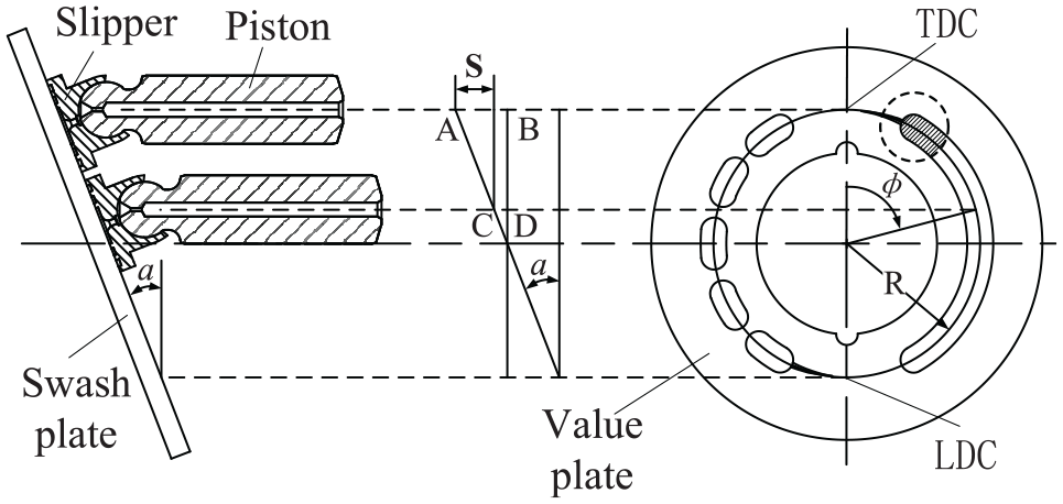
The kinematic analysis of the piston.
Plunger axial stroke s = Lab − LCD, According to the geometry in the figure relationship and motion law of plunger pump. The axial displacement equation of the plunger is:

Where s is the axial displacement of the plunger, ω is the Angular velocity of the cylinder block, t is the time, α is the swashplate angle, R is the radius of the distribution circle of the piston plug.

When the constant-pressure pump was operating, with rotation of the pump cylinder block, the continuity equation of flow in the piston chamber was expressed as follows.
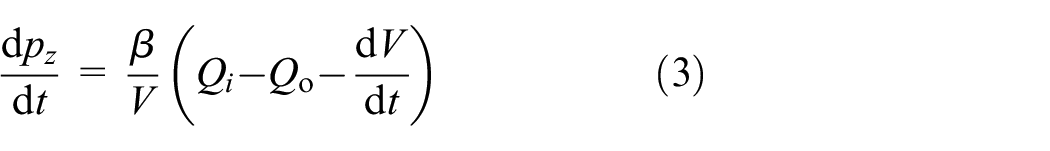
The change of flow in the piston chamber was expressed as follows:

Where Cd is flow coefficient, φ is the rotation angle of the piston, A(φ) is flow matching area, pz is pressure in the piston chamber, pp is the pressure at the discharge pump that is connected with the piston chamber, V is piston chamber volume, and β is volume elastic modulus of hydraulic oil.
The flow matching area in equation (3) referred to the overlapping area that was formed when the distribution groove of the valve plate relatively rotate to the piston plug. The changing process could be divided into six phases: access to the triangular groove, the increase of upswept area, the increase of linear area, the formation of maximum area, the decrease of the linear area, and the decrease of upswept area. Through theoretical calculation and Matlab solution, the curve of flow matching area was shown in Figure 2. 14
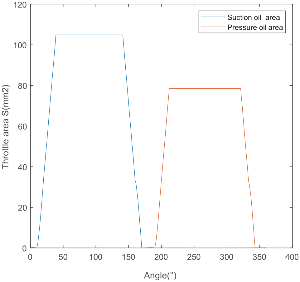
The flow matching area.
The model of a single-piston was established in the AMESim software, which was shown in Figure 3. Control parameters, including α and ω, were decided by external signals.

The single-piston model.
The model of constant displacement pump
The model of the constant displacement pump consisted of nine pistons, effective volume, the suction circuit, and the discharge circuit. And leakages were also set up for the model. Meanwhile, the research also set effective volume between the piston chamber and the valve plate and between the piston chamber and the oil pressure zone. It would directly affect the characteristics of the pump fluctuations. The super submodel of the constant displacement pump established basis on mapping and calculation was also included in the model of the constant pressure pump.
The kinetic model of adjustable mechanism
The force balance equation of the constant pressure valve was expressed as follows:

Where ps is the pressure the pump produced at work, Av is the port area of the constant pressure valve, F0 is the preload of the pressure spring, mv is the quality of both the motion part of the constant pressure valve and three third of the spring, xv is the displacement of the constant pressure valve, f is the viscous damping coefficient, and Ks is the sum of the rigidity of the pressure spring and that of the hydraulic motive force.
The flow continuity equation of the constant-pressure valve port was expressed as follows:

Where qv is flowed through the valve port of the constant pressure valve, Kq is the flow gain of the constant-pressure valve port, p1is the pressure of the left port of the variable piston, Kp is the pressure coefficient of the flow in the constant-pressure valve port, A1 is the action area of the left chamber in the oil cylinder, V1 is the volume of the left chamber in the oil cylinder, C0 is the leakage coefficient of the oil cylinder, and Eβ is volume elastic modulus of hydraulic oil.
The force balance equation of the variable piston cylinder was expressed as follows:

Where K is the rigidity of the spring,
The reluctance torque exerting on the swashplate was mainly constituted of the reluctance torque that the variable cylinder exerted on the swashplate (represented by M), the unbalance torque that the piston exerted on the rotating swashplate (represented by M1), the sliding friction torque that blocked the swashplate to rotate (represented by M2), the friction torque between the slippers and the spherical hinge (represented by M3), the swashplate torque that resulted from the weight of the swashplate (represented by M4). Among the above parameters, M resulted from the reactive force of the acting force F0. The force balance equation for the swashplate rotation was expressed as follows. When the swashplate angle

When the swashplate angle

Where L is the arm of the variables force, and J is the rotating inertia of the swashplate. The dynamic response equation of the adjustable mechanism was obtained after equations (5)–(9) were combined.
The model of constant-pressure pump
It comprised the model of the constant displacement pump, the model of variable displacement and the model of the constant-pressure valve, of which one was the self-operated pressure regulate valve, and the other was the long-distance pressure pilot valve. With a constant-pressure valve, the pump controlled the variable piston to swing the swashplate. In this way, the requirements for constant pressure were satisfied. The fixed pressure of the system was regulated by the spring of the constant-pressure valve. When the pressure of the oil discharge reached the regulated pressure of the constant-pressure valve, the pump automatically adjusts the flow and the pressure at the pump outlet was constant. When the pressure of the oil discharge was lower than the regulated pressure, the system was adjusted to the pattern of full discharge output, operating as the constant discharge pump. Based on the surveying and mapping data, the DR model and the DRG model of the constant-pressure valve was established in AMESim. The specific dynamic simulation model of the constant-pressure pump was shown in Figure 4. The main parameters of the simulation model was shown in Table 1.

The model of dynamic test of a constant pressure pump.
Main parameters of the simulation model.

Experimental tests on the dynamic characteristics of the constant-pressure variable displacement pump
To consider the response characteristics of various parts of the constant-pressure pump, the test built up a principle figure of the pressure characteristics of the constant-pressure pump in Figure 5. As can be seen from Figure 5, V1 is internal constant-pressure valve DR, V2 is internal long-distance constant-pressure valve DRG, V3 is long-distance pressure pilot valve, V4 is an electromagnetic proportional directional valve, and V5 is electromagnetic overflow valve. By manipulating V1, V2, V3, V4, and V5, different tests were done for the constant-pressure pumps on their power frequency pressure pulsation, internal unloading, external directional valve flow unloading, long-distance overflow unloading, the unloading characteristics of the flow pressure control under different flows and pressure. Figure 6 shows the physical drawing of the constant pressure pump test bench.

The experiment principle of a constant pressure pump test bench.

Physical drawing of constant pressure pump test bench.
Analysis of the simulative results and the experimental results
Pressure fluctuation in power frequency condition
Specific operations were: close V3 and V4 completely; adjust the pressure of V1 to 20 MPa; and adjust the pressure of V5 (which was regulated as the load) to 5, 10, and 15 MPa, respectively. The test results were shown in Figure 7 as follows:

The characteristics of pressure fluctuation in power frequency condition.
It could be seen from Figure 7 that the simulative results and the experimental results were consistent. The amplitude of the pressure fluctuation in the discharge outlet of the pump increased with the increasing load pressure. During this period, the swashplate remained at the position of maximum pump discharge, acting as the constant discharge pump.
Analysis of the internal unloading characteristics
Specific operations were: close V3 and V4 completely; adjust the opening pressure of V5 to exceed the regulated pressure of V1; swift V5 on and off in turn so that internal pressure unloading was realized; and adjust the pressure of V1 to 5, 10, and 15 MPa, respectively. The test results were shown in Figure 8.

The characteristics of pressure response in internal unloading condition.
Figure 8 showed that the simulation results and experimental results were consistent under three kinds of pressure states. When V5 was switching on and off in turn, the constant-pressure pump transformed from non-loaded maximum discharge to interior unloading, and the pressure of the discharge port gradually increased to the regulated pressure of V1. About 180 ms was spent on the process, and the pressure remained still for 300 ms. The overshoot for pressure was 5 MPa. In addition, when the internal unloading and discharge pressure were stable, there were still interior circulation and fluctuation. And the higher the pressure was, the larger the amplitude of the fluctuation was. This phenomenon was consistent with the characteristics of the power frequency pressure fluctuations. When V5 continued its pattern of being powered on and off, the pump transformed from internal unloading to the state of non-loading maximum discharge. The discharge pressure of the pump tumbled, and the swashplate switched from the minimum angle to the maximum angle swiftly. The response time for the swashplate to remain stable was 75 ms, after which the pressure at the pump port was 0.5 MPa.
Analysis of the flow unloading characteristics of the external directional valve
Specific operations were: close V3 and V4 completely; input square wave signals to V4 to control the on and off of the power. When V4 was closed, internal unloading was realized in V1; and when V4 was opened, through the throttling action of V4, constant-pressure control was realized as the swashplate angle was adjusted. The cycle of the square wave signal was 2 s, and the amplitude ranged from 0 to 10 V. In addition, during the simulation test and experimental test, to guarantee that the constant-pressure pump could operate at the state of external flow unloading, it is required to define the amplitude of the square wave signal of V4 basis on regulated pressure of V1. The results were shown in Table 2.
Comparison between setting pressure of the valve V1 and square wave signal amplitude.

The curve of external flow unloading characteristics in the constant-pressure pump was shown in Figure 9. As seen from the curves, the simulative results and the experimental results agreed well with each other. As V4 stopped being switched on, the discharge outlet pressure of the constant-pressure pump would sink significantly. As V4 stopped being switched off, the discharge outlet pressure of the constant-pressure pump would surge significantly. Also, with the increase of pressure, the time for decompression and pressure boost would be shortened. The reason was that: when V4 was closed, internal unloading happened in V1, where the swashplate angle of the pump remained at its minimum value, and the discharge pressure was the same as the regulated pressure of V1; as V4 was switched on, the discharge port was suddenly exposed to the external environment, where pressure boost occurred. At the same time, the swashplate swung from a certain position to gain the minimum angle until the pressure at this state was steady. In addition, as the pressure increased, the swashplate response became quicker.

The characteristics of pressure response in external flow unloading condition: (a) the experimental result and (b) the simulation result.
Analysis of the unloading characteristics of thelong-distance pressure pilot valve
Specific operations were: adjust the pressure of V1 and V5 until it rose to the maximum running pressure of 22 MPa; adjust the input signal of V4 until it was closed completely, and switch on and off V3, in turn to control the on and off the state of V2 so that the swashplate rotated to change the discharge. When the pressure of V3 was regulated to 5, 10, and 15 MPa, respectively, the test curves were obtained as shown in Figure 10.

The characteristics of pressure response with a remote pressure control valve.
As seen from Figure 10, the simulation results and the experimental results were consistent under three different pressure states. When V3 was switching on and off in turn, the constant-pressure pump was transformed from the state of non-loading maximum discharge to the state of internal unloading, and the discharge port pressure gradually rose from 3 MPa to the regulated pressure value of V3. The time for the discharge port pressure to mount was 160 ms, and the time for the pressure to remain steady was 300 ms. The overshoot amount of pressure was 2 MPa. The main reason lied in that the cushioning effect was strengthened as the tube volume at the discharge port was broadened. In addition, when the pressure of the long-distance pressure pilot valve reached 15 MPa, the internal fluctuation in the pump was violent and the stability of the pressure worsened. When V3 was switched on and off, the pump was transformed from the state of internal unloading to the state of non-loading discharge. The pressure at the discharge port gradually lowered and the swashplate swung from the minimum-angle position to the maximum-angle position. The response time was 200 ms, and the pressure was maintained at the value of 3 MPa.
Long-distance pressure control and analysis of the flow unloading characteristics
Specific operations were: adjust the pressure of V1 and V5 until it rose to the maximum running pressure of 22 MPa; define the pulse signal of V4 to control its on and off state. When V4 was closed, internal unloading happened in V2; when V4 was opened, with its throttling operation, the swashplate of V2 was controlled and the external flow unloading was realized.
Pulse signals and the unloading characteristics of internal flow
The regulated pulse signal of V4 was a cut-off pulse signal with an amplitude of 8 V. The pressure of V2 was regulated at 5, 10, and 15 MPa. The characteristics of external flow unloading with a set pulse signal was obtained in Figure 11. The simulative results and the experimental results agreed well with each other. The moment when V4 was switched off, the discharge port became airtight. Thus pressure boost formed. However, as the pulse signal happened very shortly, the boost amplitudes under different pressures reach about 2 MPa.

The characteristics of external flow unloading with a set pulse signal.
Square wave signals and the unloading characteristic of external flow
The pressure of V3 was set as 10 MPa. The square wave voltage of V4 was regulated to control the on and off, where the cycle of the square wave signal was 2 s, and the amplitude of the signal was set as 1.5, 3, and 8 V, respectively. The test results were obtained and shown in Figure 12 as follows.

The characteristics of external flow unloading with a set square wave signal: (a) the simulation result and (b) the experimental result.
As seen from Figure 12, the simulative results agreed well with the experimental results. When the voltage signals of V4 were 1.5 and 3 V, the valve port of V4 was able to throttle. When the pump was working at a constant-pressure state, and when the V4 was switched, the pressure at the discharge port would sink, which was consistent with the flow unloading characteristics in the external directional valve. When the voltage signal of V4 was 8 V, the throttling function of V4 was extremely weak. At this time, the pressure of the discharge port failed to meet the regulated pressure of V3. What’s more, the pattern of the constant displacement pump was formed when the swashplate rotated to the position with the maximum angle.
Conclusion
Through modeling, simulation, and experimental analysis, the paper tested dynamic and static pressure characteristics of the constant-pressure pump from such perspectives as power frequency fluctuation, internal unloading, external directional valve flow unloading, long-distance overflow unloading, and flow pressure control unloading. In this way, the precision of the constant-pressure pump model was verified.
Through analysis on test results under different conditions, it could be deduced that there was steady pressure fluctuation in the constant-pressure pump under any working conditions and that the higher the discharge port pressure was, the larger amplitude the pressure fluctuation was. During the dynamic process, the pressure response time and the amount of overshoot changed with the changing regulated pressure of the constant-pressure valve. The response time for pressure increase was as long as about 180 ms, and the response time for pressure decrease was as short as 75 ms. By comparing Figure 8 to Figure 10, it can be seen that when there is non-flow pressure cut-off unloading, compared to the overshoot of DRG-controlled circuit response, the overshoot of DR-controlled circuit response is bigger, and the time demanded being steady was shorter. The stability of dynamic characteristics of the constant-pressure pump with flow unloading was better than that of non-flow unloading. Therefore, through an increase of the circuit damping and the outlet’s effective volume of the simulation model in the constant-pressure pump, the dynamic stability of the model can be improved.
Footnotes
Handling Editor: Chenhui Liang
Declaration of conflicting interests
The author declared no potential conflicts of interest with respect to the research, authorship, and/or publication of this article.
Funding
The author disclosed receipt of the following financial support for the research, authorship, and/or publication of this article: The authors are grateful for the financial support of the applied basic research program of Shanxi Province, China (201901D111300).