
Abstract
The imaging quality of the synthetic aperture system is sensitive to the positioning accuracy of the sub-aperture primary mirror. A novel flexible mounting structure of bimetallic material is proposed for the athermalization of the sub-aperture primary mirror of the Fizeau Synthetic Aperture Telescope – which is composed of seven sub-aperture. The axial position accuracy of the sub-aperture primary mirror must be less than 5 µm under 10°C temperature rise to meet the requirements of the optical system. Firstly, a single mounting unit is analyzed theoretically, and the initial parameters are determined. The conceptual design of the mounting structure is carried out by using initial parameters. The orthogonal optimization algorithm and range analysis are used to optimize the structural parameters. The finite element model of the flexible mounting structure is established and the coupled thermal-mechanical simulation analysis is performed. Then the thermal sensitivity test of the sub-aperture primary mirror mounting structure was carried out. Under the effect of a temperature rise of 10°C, the axial displacement of the sub-aperture primary mirror mounting surface is less than 3 µm. Finally, the synthetic aperture system is assembled, and the optical test verifies that the synthetic aperture system has good imaging capabilities.
Keywords
Introduction
From the birth of the world’s first telescope in 1609 to the present, the diameter of the telescope system has developed from the initial centimeter level to the modern large telescope of several meters or even tens of meters. 1 As we all know, the larger the aperture of the telescope, the longer the focal length, the better it is to obtain a stronger light collection ability and higher resolution. 2 However, manufacturing large-aperture telescopes with a single aperture will face many challenges. First, the preparation of large-aperture mirrors is not only technically difficult, but also the production cycle of the mirror blanks is generally relatively long. Secondly, according to past experience and statistical laws, the cost of monolithic optics increases faster than diameter squared. 3 A further increase in the aperture will bring unbearable manufacturing costs.4,5 In addition, large-aperture mirrors have reduced usability due to aberration changes caused by their own gravity and temperature changes. The optical synthetic aperture imaging technology achieves the resolution of an equivalent large-aperture telescope by combining multiple separated sub-aperture systems. The single-channel sub-aperture has the characteristics of small diameter, low mirror manufacturing difficulty, low cost. Therefore, the sparse aperture telescope can break through the technical bottleneck of a single large-aperture telescope.
In 1978, the University of Arizona in the United States designed a synthetic aperture imaging system MMT composed of six sub-apertures with a 1.8 m aperture. 6 The equivalent aperture can reach 4.45 m. 7 The US Air Force Laboratory built a Myerson-style synthetic aperture system composed of four sub-apertures with a diameter of 20 cm in 1988, but it was only in the laboratory research stage and no field tests were carried out. 8 The Massachusetts Institute of Technology designed the ARGOS (Adaptive Reconnaissance Golay-3 Optical Satellite) system in 2000. 9 The system is composed of three 21 cm aperture sub-apertures with an equivalent aperture of 0.62 m. Researchers from Lookhead Martin in the United States also proposed and developed three prototype structures of 9-sub-aperture optical synthetic aperture telescope systems with different sub-aperture arrangements. Among them, the aperture of each sub-telescope of the Radial Telescope Array Testbed system is 0.1 m, and finally can reach the resolution of the equivalent aperture of 0.65 m 10 . Each sub-aperture of the STAR-9 system is 0.125 m, which can achieve the resolution capability of a 0.61 m single-aperture telescope. The MIDAS concept synthetic aperture system has a sub-aperture diameter of 0.35 m, which can reach the resolution of a 1.5 m single-aperture telescope. 11 The Changchun Institute of Optics, Fine Mechanics and Physics has also conducted research on optical synthetic aperture imaging technology. The imaging characteristics of the two-aperture principle verification platform have been studied, and the system resolution has been increased to 2.1 times that of a single-aperture. 12 The three-aperture array camera of the Institute of Optoelectronics, Chinese Academy of Sciences, achieves an effect that is very close to the equivalent aperture resolution of the system design under laboratory conditions. 13
Sparse-optical-synthetic-aperture telescope is one of the important development directions of future large-aperture telescope. 14 However the imaging quality of synthetic aperture systems is sensitive to the relative position accuracy between sub-apertures. The axial positions of the sub-aperture primary mirrors of the optical system design are the same. If the position accuracy between the sub-apertures exceeds the allowable range of the optical system, the image quality of the system will drop sharply. Therefore, the current synthetic aperture cameras are mainly used in laboratories with stable environments or large and complex working chambers. However, in the fields of space earth observation and high-energy matter detection, the working environment of the camera is very complicated, and it is difficult to meet the harsh environmental requirements of the synthetic aperture camera. Therefore, how to improve the environmental adaptability of synthetic aperture cameras will be of great significance to the wide range of engineering applications of synthetic aperture cameras.
In this paper, the mounting structure of the sub-aperture primary mirror of a Fizeau Synthetic Aperture Telescope composed of 7 sub-apertures is studied, and a primary mirror mounting structure composed of bimetal rods with close to zero expansion characteristics is specially designed. Based on the design results, the sub-aperture mounting structure was developed. The test results verify the correctness of the theoretical analysis results and the rationality of the structural design. This paper is based on conventional metal materials with large linear expansion coefficients, and cleverly uses the principle of flexible mechanism to combine them into a low linear expansion mounting unit in a specific direction. The innovative application of the mounting unit to the optical element mount of the synthetic aperture telescope improves the thermal stability of the synthetic aperture system. The low thermal sensitivity mounting unit design method proposed in this paper will provide a new idea for the athermal design of space telescope optomechanical structure, and has certain significance for realizing high-quality imaging of space optical loads in complex space thermal environments.
Introduction of synthetic aperture telescope optical system
The synthetic aperture optical system of this paper uses a seven-aperture sparse aperture structure, with one sub-aperture system in the center, and the remaining six sub-aperture systems are uniformly arranged around the center aperture according to a circular distribution. The optical system layout is shown in Figure 1. After the light is emitted from the sub-aperture system, it enters the beam combining optical system through the reflecting prism. The beam combining optical system is responsible for converging the light of each sub-aperture system to the image surface position of the synthetic aperture system according to the corresponding spatial arrangement law, so as to realize the coherent imaging of the light of each sub-aperture. The focal length of the entire optical system is 1360 mm, and the pixel size of the detector is 5.5 μm. The working spectrum of the system is 1064nm working spectrum and 632.8nm inspection spectrum. The center distance between the sub-apertures is 130 mm, and the equivalent diameter of the system is 360 mm. The angular resolution of the entire imaging system is better than 10μrad.

Synthetic aperture optical system layout.
Each sub-aperture is a refractive-reflective system composed of an RC two-reflection system and a corrective lens group. The diameter of the entrance pupil of the sub-aperture is 100 mm, the diameter of the secondary mirror is 23 mm, and the total length of the system is 110 mm. In order to ensure the imaging stability of the entire system, the position accuracy of the sub-aperture system must be clearly stated. Among them, the optical axis pointing accuracy of the sub-aperture system is better than 8 μrad, and the accuracy requirement can be met by means of assembly and adjustment. The axial positioning accuracy of the primary mirror of the sub-aperture system is better than 5 μm/10°C. Therefore, a new type of mounting structure is designed to meet this thermal stability requirement.
Design of sub-aperture primary mirror mounting unit
The choice of materials
The material selection of the mounting unit should comprehensively consider the material’s thermal expansion coefficient, elastic modulus, workability, and other indicators. In order to achieve the zero-expansion characteristics of the mounting unit, firstly, Invar material with a lower expansion coefficient will be considered. However, the material inconsistency between the Invar material mounting structure and the titanium alloy tube and the mirror chamber is prone to bimetallic effect, that is, after the system is subjected to thermal load, the installation interface between different components will have stress concentration, which will affect mirror surface figure accuracy. Therefore, the structure of the mounting unit that is in contact with the mounting surface needs to use the same material as the tube and the mirror chamber. The titanium alloy material should be choice. However, the relatively high coefficient of expansion of titanium alloy cannot meet the requirement of low coefficient of expansion. Another material with larger coefficient of expansion is chosen to be placed inside the titanium alloy mounting unit as a drive to achieve a low linear expansion coefficient in one direction. At the same time, in order to meet the stability requirements of the mirror mounting, the mounting unit is determined to be made of titanium alloy material with a low expansion coefficient (TC4) and aluminum Alloy (7A09) with a higher expansion coefficient. The properties of the above two materials are shown in Table 1.
Material properties selected in the mounting unit.

Theoretical analysis of mounting unit
There are two main ways to realize the zero-expansion structural unit through the difference in the thermal expansion coefficient of the bimetal. One is to bond the rod units of two materials together to form a composite rod. The bending deformation of the bi-material composite rod after heating offsets the elongation deformation along the direction of the bi-material rod, so that the bi-material rod exhibits zero expansion characteristics.15–17 Although this approach can achieve zero expansion, the bi-material composite rod has obvious stress concentration in the contact part of the two materials during the thermal deformation process, which is prone to damage. Therefore, the bi-material composite rod is not suitable for the mounting of the primary mirror. The second way to achieve this is different from the way of bi-material composite rods. It reasonably constitutes a polygon by combining rods of two different materials. During thermal deformation, the expansion in one direction is offset by the expansion in the other direction, so that the polygonal structure can achieve zero expansion in a certain direction.18,19
First, the conceptual design of the mounting unit is shown in Figure 2. The mounting unit is mainly composed of two materials, and it is assumed that the rods are connected by an ideal hinge. Among them, rod a and rod e use materials with a low linear expansion coefficient, and rod c use materials with a higher linear expansion coefficient. After the mounting unit is heated, the elongation of the rod c will be greater than the elongation of the rods a and e, so that the entire mounting unit is stretched in the horizontal direction. The horizontal expansion of the mounting unit will restrain the expansion in the vertical direction, so the vertical direction of the mounting unit may be close to zero expansion.
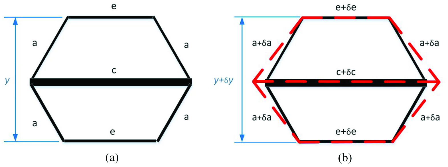
Working principle diagram of mounting unit: (a) before deformation and (b) comparison before and after deformation.
The theoretical analysis of the mounting unit is carried out, and the relationship between the vertical thermal expansion coefficient of the mounting unit and the geometric dimensions and physical properties of each rod is derived.
Assuming that the vertical distance of the mounting unit is y, the thermal expansion coefficient of the rod a and the rod e are αa, and the lengths are respectively a and e, and the thermal expansion coefficient of the rod c is αc and the length is c. The geometric relationship before heating can be expressed by the following formula:

The geometric relationship of the mounting unit after being heated can be obtained:

where δy is the vertical height change of the mounting unit, δa is the length change of the rod a in the mounting unit, δc is the length change of the rod c in the mounting unit, and δe is the length change of the rod e in the mounting unit. According to the physical properties of the material, the length of each member changes after being heated:


Among them, according to the limitation of the size of the primary mirror and the size of the mirror tube, the length of the rod e is set to 38 mm. Then the relationship between the thermal expansion coefficient αy in the y direction and the rod a and the rod c in the mounting unit is established using the above formula. Expressed by the following formula:

The above-mentioned analytical three-dimensional function model is shown in Figure 3(a). In Figure 3(a), the x- and y-axes represent the lengths of rod a and c, respectively, and the z-axis represents the thermal expansion coefficient of the mounting unit in the vertical direction. The blue plane perpendicular to the z-axis indicates that the expansion coefficient is zero. The intersection of the blue plane and the color map is the solution set (a, c) of the vertical expansion coefficient of zero. The solution set shown in Figure 3(b) indicates that the points on this line can make the vertical expansion coefficient of the mounting unit close to zero.

The relationship between the length of rod a, c and the coefficient of thermal expansion in the vertical direction of the mounting unit: (a) vertical expansion coefficient versus (a, c) function graph and (b) solution set (a, c) with vertical expansion coefficient of 0.
According to theoretical analysis, the relationship between the vertical expansion coefficient of the mounting unit and the geometric dimensions of the members of the mounting unit is established, which provides a theoretical basis for the later design. Considering the overall size and machinability of the mounting unit, the rounded size parameters of each rod in the mounting unit are shown in Table 2.
Dimension parameters of each rod in the mounting unit.

Design of the mounting structure of the sub-aperture primary mirror
Conceptual design of mounting structure
This section completes the further design based on the geometric dimensions of the mounting unit obtained from the theoretical analysis. In the theoretical analysis, the rods are connected by ideal cylindrical hinges, that is, assuming that there is no gap between the hinges. A small displacement transmission with zero error can be achieved under ideal conditions. However, the error introduced by the cylindrical hinge in practical engineering applications is big, and it is not suitable for the mirror mounting with high precision. Therefore, a flexible hinge is used to replace the cylindrical hinge to realize the transmission of micro-displacement.
In the mounting unit, the rod a and the rod c are connected by a pin. There are flexible hinges at both ends of the rod a. The flexible hinge has two main functions: (1) The flexible hinge can provide a flexible rotation pair between the rods; (2) Flexible hinge can also reduce the influence of assembly error and assembly stress on the surface figure accuracy of the primary mirror.
The primary mirror assembly includes a primary mirror chamber, a mounting unit and upper and lower mounting rings. The primary mirror is fixed in the primary mirror chamber by a pressing ring. At the same time, the outer cylindrical surface of the primary mirror chamber should have a higher cylindricity to ensure a smaller tilt error when matched with the mirror tube. Three mounting units are evenly distributed on the back of the primary mirror chamber. The upper and lower mounting surfaces of the mounting unit should have good flatness and roughness to ensure the installation accuracy. The lower mounting ring cooperates with the bottom of the mirror tube to realize the connection between the primary mirror assembly and the mirror tube. The structure of the mounting unit and the installation relationship of the primary mirror assembly are shown in Figure 4.

Primary mirror mounting structure: (a) mounting unit structure and (b) the installation relationship of the sub-aperture primary mirror structure.
Optimized design of mounting structure
In the previous section, the flexible hinge replaced the cylindrical hinge in the ideal state assumed in the theoretical analysis, which will inevitably cause the thermal characteristics of the designed primary mirror mounting structure to deviate from the theoretical analysis. Therefore, it is necessary to correct the deviation introduced by the actual design through optimization, so as to realize the nearly zero expansion of the mounting unit in the vertical direction.
In order to prevent parameter coupling in the mounting unit and improve optimization efficiency, the orthogonal optimization method is used for parameter design in this paper. 20 The geometric dimensions of the mounting unit structure include: the thickness t of the mounting unit, the width h of the mounting unit, the relative angle θ of the notch of the flexible hinge, the distance L between the two vertices of the Hooke hinge, and the diameter D of the inscribed circle of the three mounting unit layout. The parameters are shown in Figure 5 below.

Size parameters to be optimized.
According to structural size constraints and processing technology, it is determined that the thickness of the mounting unit is 4 mm ≤ t ≤ 6 mm, the width of the mounting unit is 5 mm ≤ h ≤ 8 mm, the relative angle of the Hooke hinge gap 30° ≤ θ ≤ 75°, and the distance between the two vertices of the Hook hinge is 1.2 mm ≤ L ≤ 3 mm, and the inscribed circle radius of the three mounting units is 70 mm ≤ D ≤ 100 mm. According to the value range of each size, the interpolation values of each parameter are uniformly selected as shown in Table 3 below. In order to analyze the relationship between the change of parameters and the displacement of the mounting surface of the mounting structure, an orthogonal test method was used to design the combination of parameters. According to the L16 (45) standard orthogonal table, 16 structural parameter combinations are used to complete the parameter optimization plan of all 1024 parameter combinations. The specific test parameter settings are shown in Table 3, and the test plan and results are shown in Table 4. The p value in Table 4 represents the displacement of the mounting structure along the vertical direction under the 10°C temperature rise condition. The value of T in Table 4 indicates the displacement of the mounting structure along the vertical direction with a temperature rise of 10°C under the condition that both rod a and rod c are made of titanium alloy. By comparing the p value and T value, it can be judged whether the designed mounting structure is effective.
Parameter factor level table of mounting unit structure.

Orthogonal test plan and results.

The next step will be to perform a range analysis on the results of the orthogonal experiment to determine the primary and secondary relationship of each factor. The results of the range analysis of each factor are shown in Table 5. P1, P2, P3, and P4 respectively represent the average value of the displacement of the mounting structure along the vertical direction in the four horizontal states of five factors. ΔP is the difference between the maximum value and the minimum value among the average values of all levels of the factors, that is, the extreme difference value. The higher the extreme difference, the greater the influence of the selected level under a certain factor on the displacement of the mounting structure along the vertical direction.
Range analysis on factors of displacement.

According to the range analysis, the order of the influence of various factors on the displacement of the mounting structure along the optical axis is as follows: The diameter of the inscribed circle of the three mounting units D, the thickness of the mounting unit t, the relative angle of the notch of the Hooke hinge θ, the width of the mounting unit h, the distance between the two vertices of the Hooke hinge L. The results of the range analysis show that the displacement variation will decrease with the increase of the diameter of the inscribed circle in the distribution of the three mounting units. The range results of other factors have little effect on the displacement variation at the submicron level. The final structure size of each parameter is determined as shown in Table 6
Design results of parameter optimization.

Engineering analysis
The next step is to perform finite element analysis on the designed mounting structure of the primary mirror to verify the rationality of the design. First, the finite element model of the mounting element is established as shown in Figure 6, and then the thermo-mechanical coupling analysis is carried out. The working condition of the mounting structure designed in this paper is in the laboratory environment of 23°C–33°C, and the simulation analysis is carried out through ANSYS to observe the displacement change of the mounting unit in the vertical direction. The simulation result is shown in Figure 6.

Mounting structure finite element model and displacement cloud diagram.
Divide into four groups within the working condition range of 10°C, and then conduct thermal-mechanical coupling. Take several node displacements in the installation surface in the deformation cloud chart for least-squares fitting, and the simulation results are sorted out in Table 7.
Simulation results of the axial displacement of the mounting surface of the mounting structure.

The simulation results show that the displacement of the mounting structure along the vertical direction increases with the temperature of the working condition, but the maximum displacement of 2.89 μm meets the axial positioning requirements of the primary mirror mounting.
Test verification
In the early stage of the design, the relevant structural parameters were selected through theoretical calculation. The errors introduced by the replacement of the kinematic hinge by the flexure hinge were eliminated through the optimization design. Then the finite element simulation was used to verify the validity of the design results. Finally, the effectiveness of the designed mounting structure and the reliability of the simulation analysis need to be verified by experiments. Therefore, the installation surface displacement measurement test under the thermal working condition of the mounting unit and the synthetic aperture imaging detection test are carried out respectively.
Displacement detection test
After the primary mirror test piece is processed, we are ready to test the vertical athermalization performance of the mounting structure under thermal conditions. In order to ensure measurement accuracy, the measurement equipment is required to have sub-micron measurement accuracy. The model DGB-5B inductance micrometer is used to complete the measurement test. The micro-displacement measurement platform is set up as shown in Figure 7.

Mounting structure micro-displacement measurement platform.
The micro-displacement measurement platform is mainly composed of three parts: the thermal control system, the mounting structure of the primary mirror, and the inductance meter measurement system. The main function of the thermal control system is to simulate the 10°C temperature rise of the mounting structure. The thermal control system has two closed-loop control circuits to control the temperature of rod a (7A09) and rod c (TC4) in the mounting structure. In the thermal control closed-loop circuit, the heating plate attached to the surface of the mounting structure as an actuator, and the thermocouple attached to the surface of the mounting structure as a sensor. The probe sensor of the inductance meter is fixed by a special support frame, and the probe is close to the measured point. After completing the measurement platform construction and test preparations, it enters the test phase. First, we turn on the thermal control system to control the mounting structure and start recording the displacement data. Until the temperature of the mounting structure stabilizes at 33°C, we close the thermal control system and continue to record the displacement data. Finally, the mounting structure is cooled to the initial temperature, and the pointer of the inductance meter returns to the zero position. The results of the test data are shown in Figure 8.

Output result of the displacement of the measured point.
The test results are divided into four stages:
Stage 1: The measuring point of the mounting unit moves down. Since the aluminum rod c in the mounting unit heats up faster than the titanium rod a, the middle rod c expands rapidly. Therefore the mounting unit is stretched in the horizontal direction to cause contraction in the z-axis direction. The phenomenon at this stage indicates that the flexible hinge in the mounting unit can replace the rotating pair to complete the transfer and transformation of motion, and also indicates that the two-material combination design can realize the modulation of the linear expansion coefficient in a single direction.
Stage 2: The measuring point of the mounting unit moves up. The temperature of the titanium rod a continues to rise with the work of the thermal control system. So the mounting structure expands in the vertical direction.
Stage 3: The displacement of the measuring point of the mounting unit is close to 3 μm and fluctuates dynamically around 3 μm. At this stage, the mounting unit rod c and rod a are both close to the preset operating temperature (33°C). The Z-direction displacement of the mounting unit is close to 3 μm. But the thermal control system adopts closed-loop control, and the heating plate was in a cyclic heating state, so displacement fluctuations occurred. This stage shows that the mounting unit meets the design requirement of less than 5 μm displacement in the Z-axis direction under a temperature load of 10°C. At the same time, the test results are close to the engineering analysis results, and the error between the simulation results and the test results is less than 10%.
Stage 4: The displacement of the measuring point of the mounting unit slowly approaches 0, and the displacement fluctuation phenomenon disappears. At this stage, the thermal control system is closed, and the mounting structure begins to cool down until it reaches the initial temperature, and the pointer gradually returns to zero. It shows that the repeat positioning accuracy of the mounting unit is good after being thermally disturbed. At the same time, the disturbance phenomenon disappears after the thermal control system is turned off, which indicates that if the mounting structure is in a stable temperature rise working environment, the displacement fluctuation phenomenon in stage three will not appear.
Synthetic aperture imaging detection test
After completing the camera assembly work, we carried out the imaging performance test of the system. First, a star point plate is placed on the image plane of the collimator, and the star point imaging diagram generated by the synthetic aperture system is compared with the theoretical analysis spot. The comparison result is shown in Figure 9. The theoretical analysis spot feature is consistent with the spot feature generated by the system, which means that the system works well.

Star point diagram comparison test of synthetic aperture system: (a) theoretical star spot diagram and (b) test star spot diagram.
After completing the star-point diagram comparison test, we replaced the star-point board of the collimator with a resolution board of No. 3. The focal plane detector of the synthetic aperture system images the resolution plate emitted by the collimator to determine the system resolution. The system prototype structure and resolution test results are shown in Figure 10. By observing the imaging results of the No. 3 resolution plate by the synthetic aperture system, it can be seen that the 12th group of fringes can be seen clearly. The corresponding line width is 21.2 μm, which is converted into an angular resolution of 4.816 μrad of the sparse aperture optical system. The resolution test result is better than the technical index of 10 μrad.
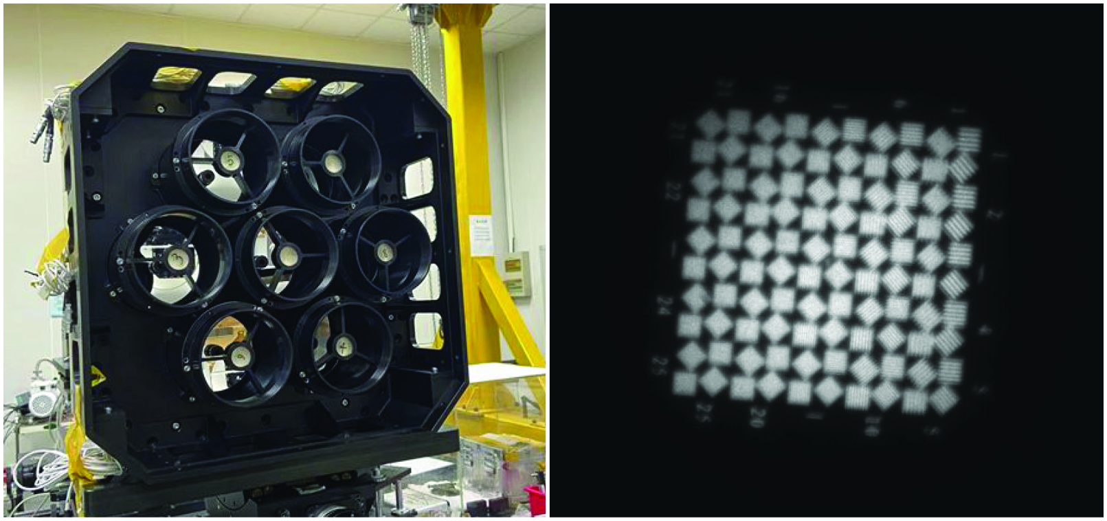
Synthetic aperture system principle prototype and resolution test results.
Conclusion
This paper takes synthetic aperture camera as the research object. In order to solve the problem of high thermal sensitivity of synthetic aperture system imaging quality to the positioning accuracy of the sub-aperture primary mirror, a novel athermalized mounting structure is proposed to realize the mounting of the sub-aperture primary mirror. The relationship between the key dimensions of the mounting unit and the vertical thermal expansion coefficient was established through theoretical analysis. At the same time, the mounting unit was conceptually designed based on the theoretical analysis results. Then we used the orthogonal optimization method and the range analysis method to complete the size optimization of the mounting unit. ANSYS was used to conduct a thermo-mechanical coupling simulation of the designed components to verify the rationality of the design. Simulation analysis results show that the designed mounting unit meets the design requirements. Then, a test prototype was processed and a test platform was built. Experiments such as micro-displacement measurement and system-level detection were carried out to verify the validity of the theoretical analysis and simulation results. The maximum error between the test results and the engineering simulation analysis results is less than 10%, which indicated that the theoretical model of the mounting unit and the finite element simulation model are established accurately. At the same time, the primary mirror mounting structure meets the system design requirements of less than 5 μm displacement in the Z-direction within the temperature range of the working condition. Finally, the seven-aperture star point diagram and resolution test result obtained by the system detection experiment shows that the system is good in imaging. The athermalized mounting structure design of the primary mirror can improve the thermal stability of the seven-aperture camera. It can also provide a reference for the adjustable thermal expansion coefficient structure design.
Footnotes
Acknowledgements
We thank Weiwei Liu for his excellent work on the camera system assembly and Changping Wang for his work on optical and structural parts processing.
Handling Editor: Chenhui Liang
Declaration of conflicting interests
The author(s) declared no potential conflicts of interest with respect to the research, authorship, and/or publication of this article.
Funding
The author(s) disclosed receipt of the following financial support for the research, authorship, and/or publication of this article: The work of this paper was supported by Youth Innovation Promotion Association of the Chinese Academy of Sciences (501100004739).